1989 MITSUBISHI GALANT steering
[x] Cancel search: steeringPage 144 of 1273
13-2
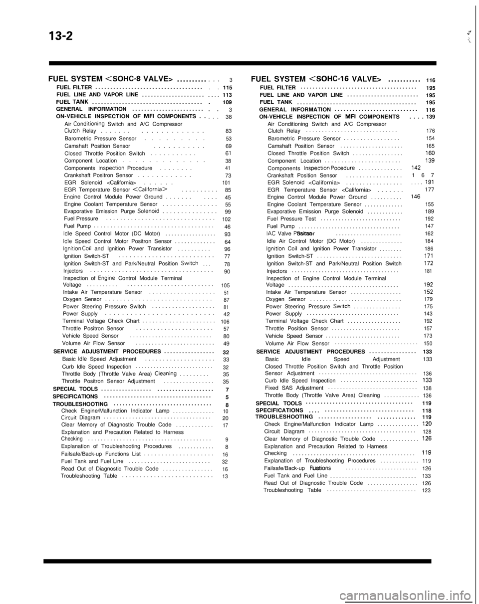
FUEL SYSTEM
..........
FUEL FILTER ....................................
FUEL LINE AND VAPOR LINE .....................FUELTANK....................................
.
GENERAL INFORMATION ........................
ON-VEHICLE INSPECTION OF MFI
COMPONENTS . .
Air
Conditionrng Switch and A/C CompressorClutch Relay ......
.
.............
Barometric Pressure Sensor .........
Camshaft Position Sensor ...........
Closed Throttle Position Switch ...........
Component Location .............
Components
Inspectron Procedure .......
.
Crankshaft Positron Sensor ............
EGR Solenoid
. . .3. .
115..,.113
. 109
. . 3
. . . 38
83
536961384173101EGR Temperature Sensor
.
85
Enqine Control Module Power Ground ......
.
....
45
Engine Coolant Temperature Sensor ...............
55Evaporative Emission Purge Solenord..............
.
99
Fuel Pressure ...............................
102Fuel Pump
...................................
.
46
Idle Speed Control Motor (DC Motor) ................
.
93
Idle Speed Control Motor Positron Sensor ............
.
64
lgnitron Co11 and Ignition Power Transistor .........
.
96
Ignition Switch-ST ..........................
77Ignition Switch-ST and Park/Neutral Position Switch
...78
Injectors..................................
.
90
Inspection of
Engrne Control Module Terminal
Voltage .........
.
..........................
105Intake Air Temperature Sensor ..................
.
51Oxygen Sensor
............................
.
87Power Steering Pressure Switch
..................
.
81Power Supply
.........................
.
42
Terminal Voltage Check Chart ......................
106Throttle Positron Sensor.....................
.
57Vehicle Speed Sensor
.........................
.
80
Volume Air Flow Sensor .........................
49
SERVICE ADJUSTMENT PROCEDURES .................
32
Basic
Idle Speed Adjustment ...................
.
33
Curb Idle Speed Inspection ..........................
32Throttle Body (Throttle Valve Area) Cleaning........
.
35
Throttle Positron Sensor Adjustment ................
35
SPECIAL TOOLS 7
.................
...................
SPECIFICATIONS ....................................
5
TROUBLESHOOTING .................................
8
Check Engine/Malfunction Indicator Lamp ..............
10Crrcuit Diagram.................................
.
20
Clear Memory of Diagnostic Trouble Code ............
17Explanation and Precaution Related to HarnessChecking......................................
.
9Explanation of Troubleshooting Procedures
...........
.
8
Failsafe/Back-up Functions List ....................
16Fuel Tank and Fuel Lrne.........................
.
32Read Out of Diagnostic Trouble Code
...............
.
16Troubleshooting Table
.........................
.
13
FUEL SYSTEM
116
FUEL FILTER .......................................
195
FUEL LINE AND VAPOR LINE ........................
195
FUEL TANK ........................................ 195
GENERAL INFORMATION ............................
116
ON-VEHICLE INSPECTION OF MFI
COMPONENTS
Air Conditioning Switch and A/C Compressor Clutch Relay .............................
Barometric Pressure Sensor .................
Camshaft Position Sensor ....................
Closed Throttle Position Switch ................
Component Location .......................
Components Inspectron Pocedure
..............
Crankshaft Position Sensor .................
EGR Solenoid
EGR Temperature Sensor
Engine Control Module Power Ground ..........
Engine Coolant Temperature Sensor .............
Evaporative Emission Purge Solenoid ............
Fuel Pressure Test ...........................
Fuel Pump ..................................
IAC Valve Positon Sensor
......................
Idle Air Control Motor (DC Motor) ..............
lgnrtion Coil and Ignition Power Transistor
.......
.
Ignition Switch-ST ...........................
Ignition Switch-ST and Park/Neutral Position Switch
Injectors ....................................
Inspection of Engine Control Module Terminal
Voltage .....................................
Intake Air Temperature Sensor .................
Oxygen Sensor .............................
Power Steering Pressure
Swatch..............
.
Power Supply ...............................
Terminal Voltage Check Chart ..................
Throttle Position Sensor .......................
Vehicle Speed Sensor ......................... . . . . 139
176
154
165
16013914216
7
..,_ 191177146
155
189192
147
162
184
186
171172181
192152
179
175
143
192
157
173
Volume Air Flow Sensor ...........................
.
150
SERVICE ADJUSTMENT PROCEDURES
...............
.
133
Basic Idle Speed Adjustment 133
Closed Throttle Position Switch and Throttle Position
Sensor Adjustment .................................
136Curb Idle Speed Inspection
.........................
.
133Fixed SAS Adjustment
.............................
.
138Throttle Body (Throttle Valve Area) Cleaning
...........
.
136
SPECIAL TOOLS
...................................
.
119
SPECIFICATIONS 118
.... ..............................
TROUBLESHOOTING ..................
.............
119
Check Engine/Malfunction Indicator Lamp ..............
120Circuit Diagram...................................
.
128Clear Memory of Diagnostic Trouble Code
............
.
126Explanation and Precaution Related to Harness
Checking ........................................
.
119Explanation of Troubleshooting Procedures
............
.
119Failsafe/Back-up
Fuctions List
........................
126
Fuel Tank and Fuel Line .............................
133Read Out of Diagnostic Trouble Code ................
.
126
Troubleshooting Table ..............................
123
Page 145 of 1273
FUEL SYSTEM
FUEL SYSTEM
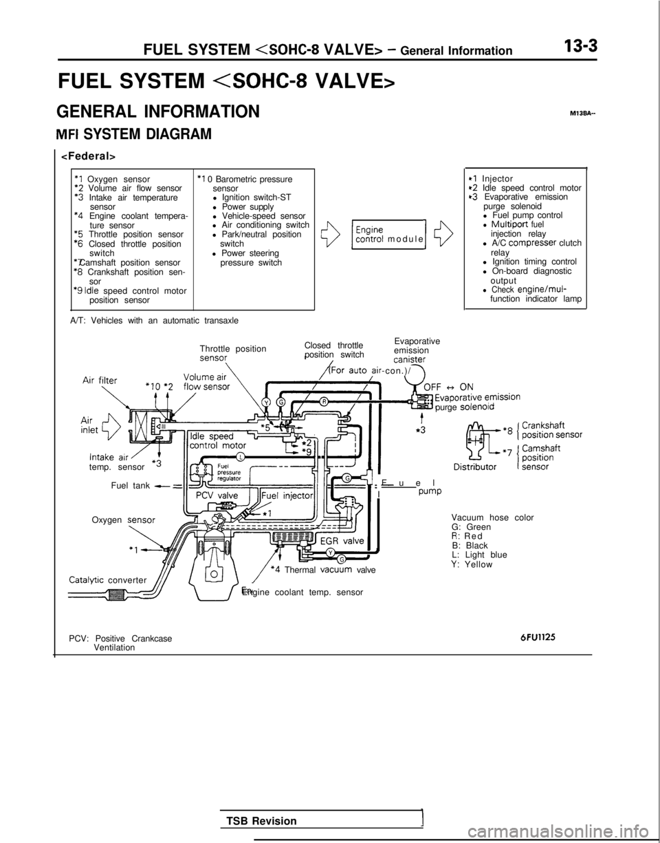
GENERAL INFORMATION
MFI SYSTEM DIAGRAM
*1 Oxygen sensor
*2
Volume air flow sensor *3
Intake air temperature
sensor *4
Engine coolant tempera-
ture sensor *5
Throttle position sensor *6
Closed throttle position
switch *7 Camshaft position sensor
*8
Crankshaft position sen-
sor
‘9 Idle
speed control motor
position sensor
*I 0 Barometric pressure sensor
l Ignition switch-ST
l Power supply
l Vehicle-speed sensor
l Air conditioning switch
l Park/neutral position
switch
l Power steering pressure switch
A/T: Vehicles with an automatic transaxle
()/ $%?i modul
e
Closed throttle Evaporative
position switch emission canister
ir-con.)/ \
10
Throttle position
temp. sensor Fuel tank
- =
Oxygen M13BA-
I
*I Injector~2 Idle speed control motort3 Evaporative emission
purge solenoid
l Fuel pump control
l Multiport fuelinjection relay
l A/C compresser clutch
relay
l Ignition timing control
l On-board diagnostic
output
l Check engine/mul-function indicator lamp
Fue
l
: -
I
pump
purge
solenolo Catalvtic
converter
\/ *4 Thermal vacu
G: Green
R: Re
d
B: Black
L: Light blue
Y: Yellow
dJJ/ U’Engine coolant temp. sensor
PCV: Positive Crankcase Ventilation
6FU1125
TSB Revision
Page 146 of 1273
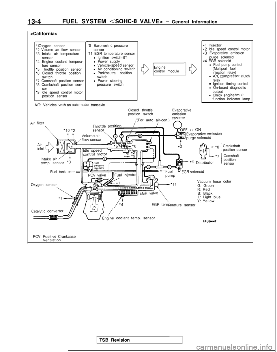
13-4FUEL SYSTEM
*2 Volume
air
flow sensor$3 Intake air temperature
sensor
*4 Engine coolant tempera-ture sensor
“5 Throttle position sensor‘6 Closed throttle position switch
*7 Camshaft position sensor*8 Crankshaft position sen-
sor
*9 Idle speed control motor position sensor “I 0
Barometric pressure
sensor
‘11 EGR temperature sensor
l Ignition switch-STl Power supply
l
Vehrcle-speed sensor
l Air conditioning switch
l Park/neutral position
switch
l Power steering pressure switchI13
Engrnecontrol module10
rl Injectort2 Idle speed control motorr3 Evaporative emission
purge solenoid
r4 EGR solenoidl Fuel pump control
(Multiport fuel
injection relay)
l A/C compresser clutchrelay0 Ignition timing control
l On-board diagnostic
output
l Check engine/muj-function indicator lamp
A/T: Vehicles
with an automatrc
transaxle
Closed throttleposition switch Evaporative
emission
/(For auto air-con.) can’ster
/ n
Vacuum hose
G: Green
R: Red
B: Black L: Light blue
Y: Yellow
erature sensor Air
filter
Fuel tank - =
Oxygen sensor
\ U /Eni coolant temp. sensor1FUO447
Crankshaft
position sensor
Camshaft
position
sensor
color
PCV: Posrtive
Crankcase
TSB Revision
Page 147 of 1273
FUEL SYSTEM
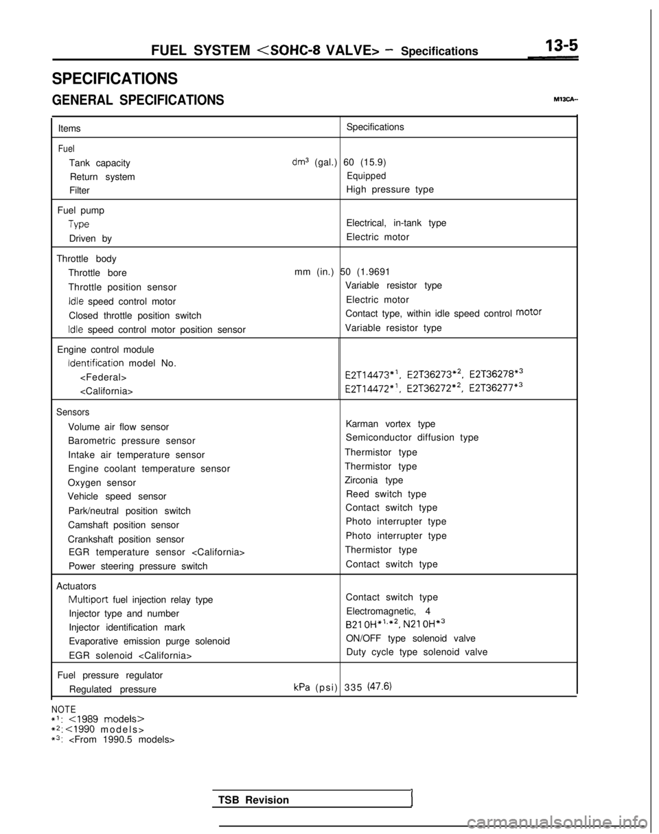
SPECIFICATIONS
GENERAL SPECIFICATIONS
Items
Fuel
Tank capacity
Return system
Filter
Fuel pump
Type
Driven by
Throttle body Throttle bore
Throttle position sensor
Idle speed control motor
Closed throttle position switch
Idle speed control motor position sensor
Engine control module Identification
model No.
Sensors
Volume air flow sensor
Barometric pressure sensor
Intake air temperature sensor
Engine coolant temperature sensor
Oxygen sensor
Vehicle speed sensor
Park/neutral position switch
Camshaft position sensor
Crankshaft position sensor EGR temperature sensor
Power steering pressure switch
Actuators
Multiport fuel injection relay type
Injector type and number
Injector identification mark
Evaporative emission purge solenoid
EGR solenoid
Fuel pressure regulator Regulated pressure
NOTE*I:
*3:
dm3 (gal.) 60 (15.9)
Equipped
High pressure type
Electrical, in-tank type
Electric motor
mm (in.) 50 (1.9691 Variable resistor type
Electric motor
Contact type, within idle speed control motor
Variable resistor type E2T14473*‘,
E2T36273*2, E2T36278*3
E2T14472”. E2T36272*2, E2T36277*3
Karman vortex type
Semiconductor diffusion type
Thermistor type
Thermistor type
Zirconia type Reed switch type
Contact switch type
Photo interrupter type
Photo interrupter type
Thermistor type
Contact switch type
Contact switch typeElectromagnetic, 4
B21 OH*‘,*2,
N21 OH*3
ON/OFF type solenoid valve
Duty cycle type solenoid valve
kPa (psi) 335 (47.6)
TSB RevisionI
Page 161 of 1273
FUEL SYSTEM
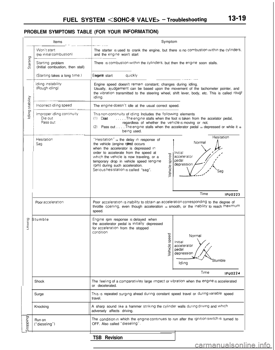
PROBLEM SYMPTOMS TABLE (FOR YOURINFORMATION)
:tShock
Surge
Knocking
0,GRun ona (“dieselrng”)
6
Items Symptom
-- -... __----. -~-
The starter IS used to crank the engine, but there IS no
combustron
wrthrn
the cylinders.
(no rnrtral combustron)
and the engine won’t start~-.-__Startrng
problem There IS combustron
wrthrn
the cylrnders.
but then the engrne
soon stalls.
(Initial combustion, then stall)
(Startrng takes a long t1me.l
I
Idling
rnstabrlrty
/ Engrne won’t start qurckly~--_~ -...
Engine speed doesn’t remain constant; changes during idling.
Usually, aludgement can be based upon the movement of the tachometer pointer, and
the
vibration transmitted to the steering wheel, shift lever, body, etc. This is call\
ed rougt
Idling.
The
engtnedoesn’t idle at the usual correct speed.
Thus non-contrnuity of rdlrng Includes the followrng elements(1) Die out
. . . . ..The
engine stalls when the foot IS taken from the accelator pedal,
regardless of whether the vehicle IS moving or not.(2)Pass out . . . ..The
engine stalls when the accelerator pedal IS depressed or while it IS berng
used.
“Hestatton” IS the delay In response of
the vehicle (engine rpm) that occurs
when the accelerator is depressed
Inorder to accelerate from the speed atwhich the vehicle is now traveling, or a
temporary drop in vehicle speed (enginerpm) during such acceleration. Hesltatron
Serious
hesstatlon IS called “sag”.
Poor
acceleration
E Stumbl
e
2
5
Time lFUO223
Poor
acceleration IS rnabilrty
to obtain an acceleration corresponding to the degree of
throttle opening, even though acceleration IS smooth, or the rnabrlrty to reach maxmum
speed.
Engrne rpm response IS delayed when .
the accelerator pedal is initrally
depressed
for acceleratron
from the stopped
condition ldllng
Stumble
Trme lFUO224
The
feeling of a comparatlvley large Impact or vrbration
when the engine IS accelerated
or decelerated.
This IS repeated surging
ahead dunng constant speed travel or dunng
vanable
speed
travel.
A sharp sound
IIke a hammer strtklng the cylinder walls during
dnvtng
and whrch
adversely affects driving.
The
condrtion In which the engrne
continues to run after the lgnltion switch 1s turned to
OFF. Also called
“dreselrng”.
TSB Revision
Page 173 of 1273
FUEL SYSTEM
MFIRELAY
IIOXYGEN SENSOR(VEHICLES FORCALIFORNIA)
g k______ -___----__ -------------
mlI
----518>
EF
!, -I
s A-08c-09
f@p&g~,,-yg@
POWER STEERINGPRESSURE SWITCH
.
---
-
1
3
14
--
-
3
1-
I
_------3
15
P
10
I [
12 t-----58
(ENG)
(DATA)
c-40-0
3
1
2
1
C-38
DATA LINKCONTROL MOTORCONNECTOR
' OXYGEN SENSOR'(VEHICLES FOR
1 TSB RevisionI
Page 180 of 1273
13-38
FUEL SYSTEM
ON-VEHICLE INSPECTION OF MFI
COMPONENTS
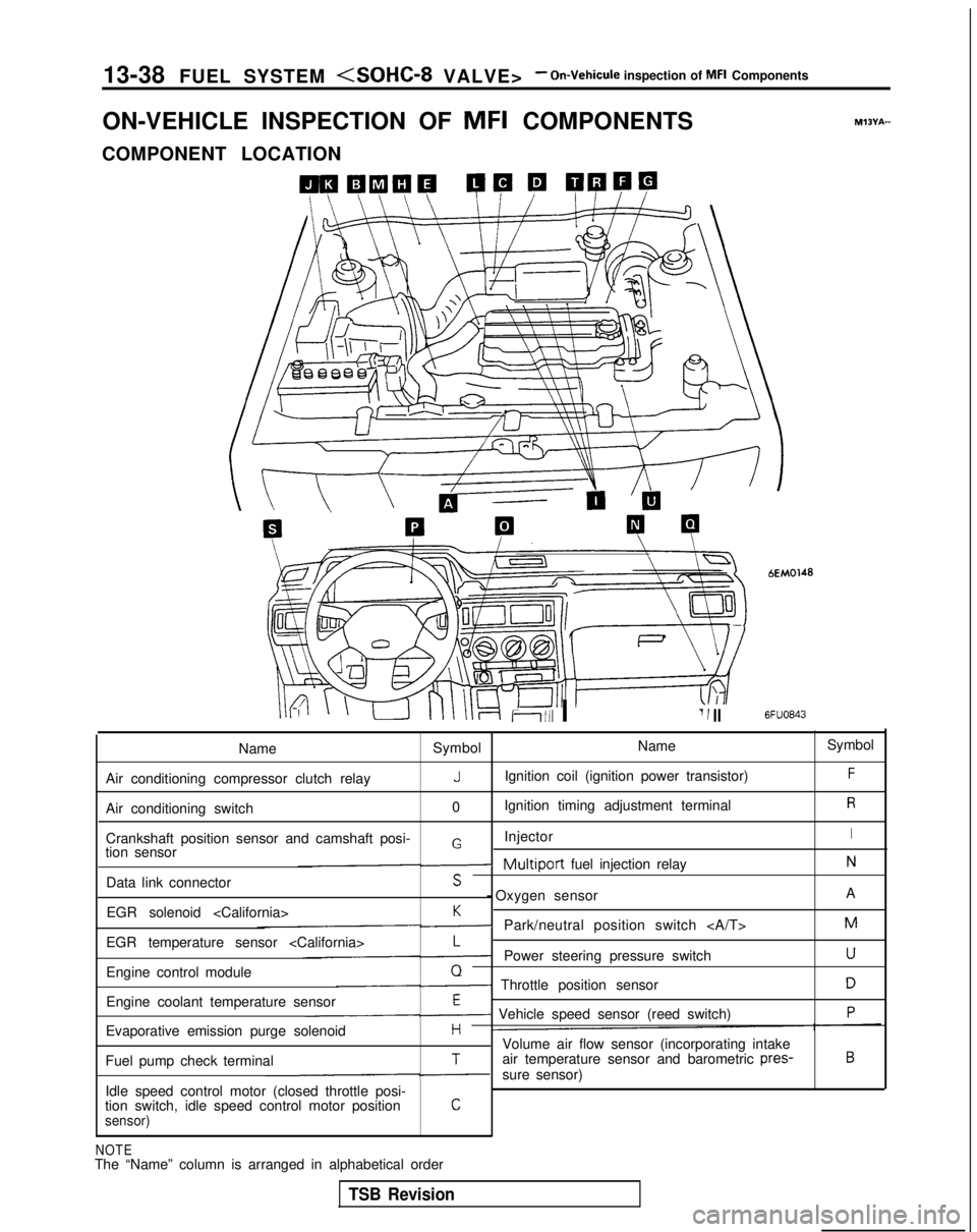
COMPONENT LOCATION
Ii111 I‘I 1 II
bEM0148
6FUO843
M?BYA-
Name Symbol Name
Symbol
Air conditioning compressor clutch relay
JIgnition coil (ignition power transistor)F
Air conditioning switch 0Ignition timing adjustment terminalR
Crankshaft position sensor and camshaft posi- InjectorIGtion sensor-Multiport fuel injection relayN
Data link connectorS - Oxygen sensor
A
EGR solenoid
K-Park/neutral position switch M
EGR temperature sensor
L-Power steering pressure switchU
Engine control moduleQ- Throttle position sensorD
Engine coolant temperature sensorE- Vehicle speed sensor (reed switch)P
Evaporative emission purge solenoidHVolume air flow sensor (incorporating intake
Fuel pump check terminalTair temperature sensor and barometric pres-B
-sure sensor)
Idle speed control motor (closed throttle posi-
tion switch, idle speed control motor position
Csensor)
NOTEThe “Name” column is arranged in alphabetical order
TSB Revision
Page 223 of 1273
FUEL SYSTEM
@ Harness sideconnector
6FU1265
n
8171615141312 11 9 1171615141312~1~1
0
I
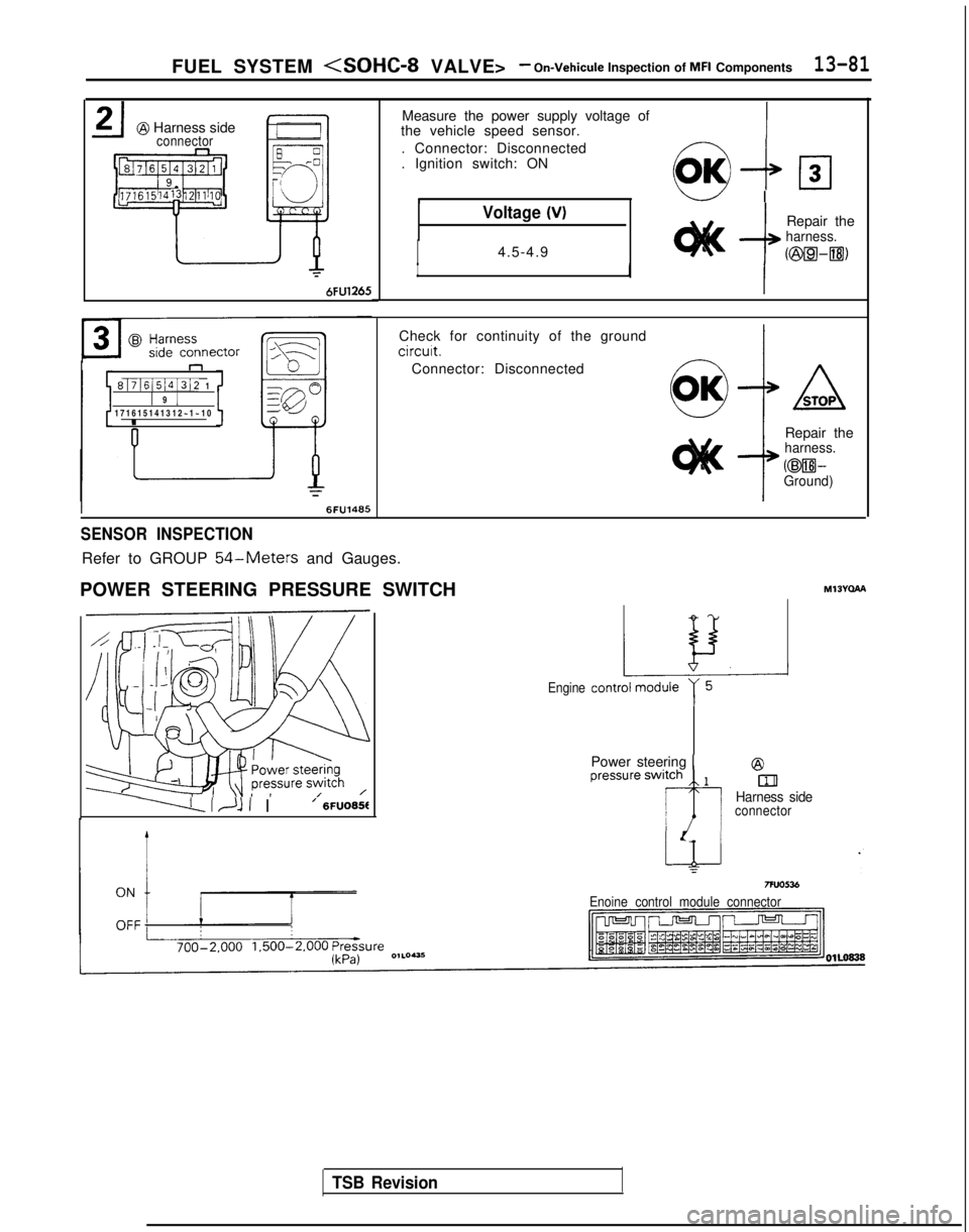
Measure the power supply voltage of
the vehicle speed sensor.
. Connector: Disconnected
. Ignition switch: ON
6&loIw I
Voltage (V)
I4.5-4.9--I
Repair theharness.
II
I
Check for continuity of the ground
circuit.
Connector: Disconnected
Repair the
harness.
@WGround)
SENSOR INSPECTION
Refer to GROUP 54-Meters and Gauges.
POWER STEERING PRESSURE SWITCH MI3Yclha
------LI~lI I’ 6FUO65f
TSB Revision
Engine
Power steering 1@
blHarness sideconnector
Enoine control module connector