Page 224 of 1273
13-82 FUEL SYSTEM -On-Vehicule Inspection of MFI Components
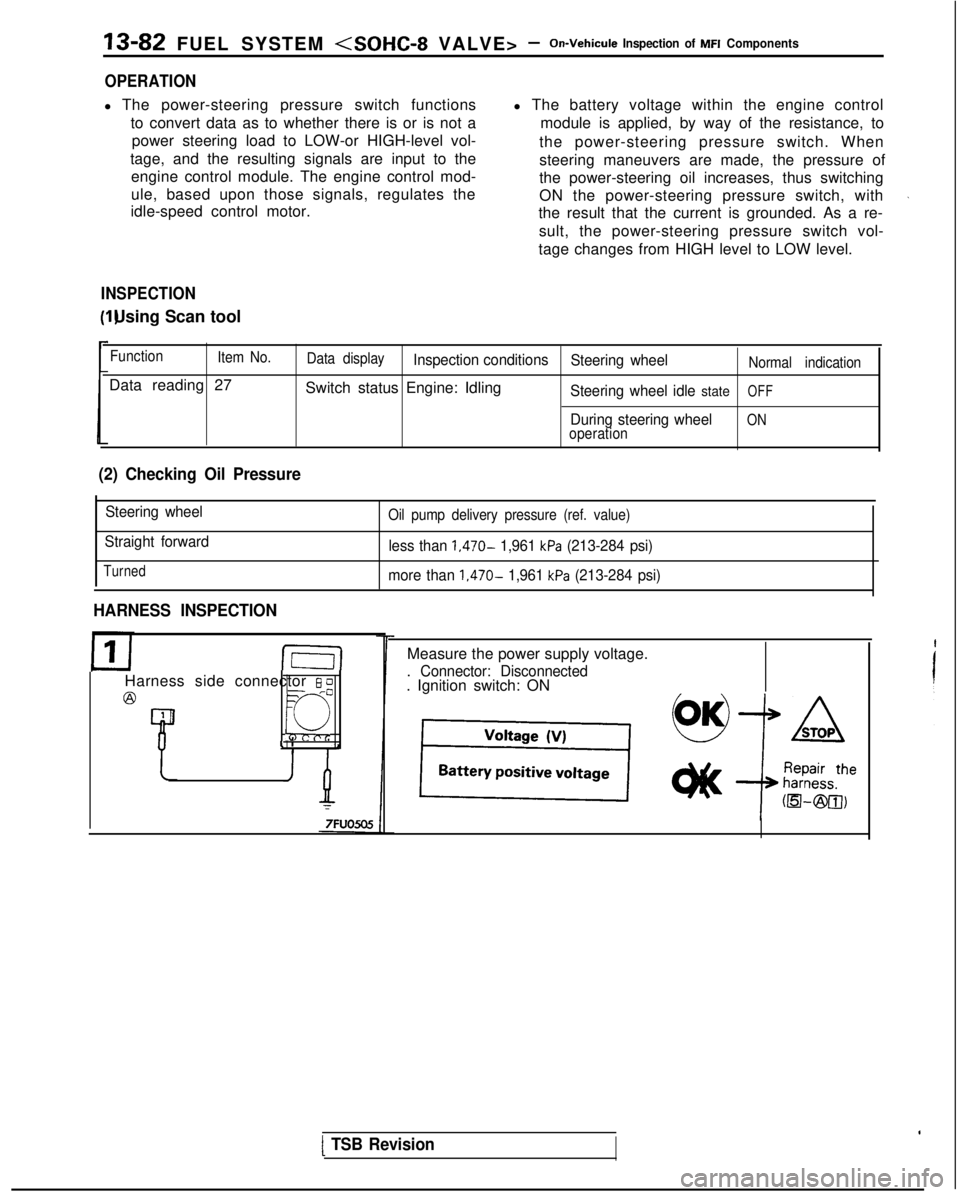
OPERATION
l The power-steering pressure switch functions
to convert data as to whether there is or is not apower steering load to LOW-or HIGH-level vol-
tage, and the resulting signals are input to the engine control module. The engine control mod-
ule, based upon those signals, regulates the
idle-speed control motor. l The battery voltage within the engine control
module is applied, by way of the resistance, to
the power-steering pressure switch. When
steering maneuvers are made, the pressure of
the power-steering oil increases, thus switching
ON the power-steering pressure switch, with
the result that the current is grounded. As a re-
sult, the power-steering pressure switch vol-
tage changes from HIGH level to LOW level.
INSPECTION I) Using Scan tool
Function
Item No.
Data reading 27
Data displayInspection conditions Steering wheelNormal indication
Switch status Engine: IdlingSteering wheel idle stateOFF
During steering wheelONoperation
(2) Checking Oil Pressure
Steering wheel
Straight forward
Turned
Oil pump delivery pressure (ref. value)
less than 1,470- 1,961 kPa (213-284 psi)
more than
1,470- 1,961 kPa (213-284 psi)
HARNESS INSPECTION
I-E-I
Harness side connector 6 0
@=- -0
Q
4 1
Measure the power supply voltage.
. Connector: Disconnected. Ignition switch: ON
[ TSB Revision
Page 249 of 1273
FUEL SYSTEM -On-Vehicule Inspection of MFI Components13-107
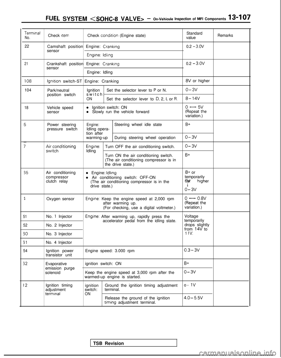
TerminalCheck ItemCheck condition
(Engine state)StandardNo.valueRemarks
22
Camshaft position Engine: Cranking0.2 - 3.ov
sensor
Engrne: ldllng
21Crankshaft position Engine: Crankingsensor
Engine: Idling0.2 - 3.ov
108
104
18
lgnrtron switch-ST Engine: Cranking 8V
or higher
Park/neutral Ignition
Set the selector lever to
P or N.o-3v
position switch switch
:
ONSet the selector lever to D, 2, L or R.8- 14V
Vehicle speed
l Ignition switch: ON
sensor l Slowly run the vehicle forwardkeFaF:hevariation.)
Power steering
pressure switch
;;ir;z;ditioning
Engine:Steering wheel idle state
Idling opera-
tion after
warming-up During steering wheel operation
Engrne:Turn OFF the air conditioning switch.
Idling
Turn ON the air conditioning switch.(The air conditioning compressor is in
the drive state.)
B+
o-3v
o-3v
B+
35
1
51
52
50
51
54
Air conditioning
compressor
clutch relay
Oxygen sensor
No.
1 Injector
No. 2 Injector
No. 3 Injector
No. 4 Injector Ignition power
transistor unit l Engine: Idling
B+ or
l Air conditioning switch: OFF-ON temporarily
(The air conditioning compressor is in the 6V or
higher
drive state.)o’- 3v
Engine: Keep the engine speed at 2,000 rpm
after warming up. kQatot8h2:
(For checking, use a digital voltmeter.) variation.)
Engine: After warming up, rapidly press the
Voltage
accelerator pedal from the idling state. temporarily
drops slightly
from
14V to1 IV.
Engine speed: 3.000 rpm0.3- 3v
Evaporative
emission purge
solenoid ignition switch: ON
Keep the engine speed at 3,000 rpm after the
warmed-up engine is started.B+
o-3v
12Ignition timing
adjustment terminal
ignition
Ground the ignition timing adjustment o- 1vswitch:
terminal.ONRelease the ground of the ignition4.0- 5.W timing
adjustment terminal.
TSB Revision
Page 260 of 1273
13418FUEL SYSTEM (SOHC-16 VALVE> - Specifications
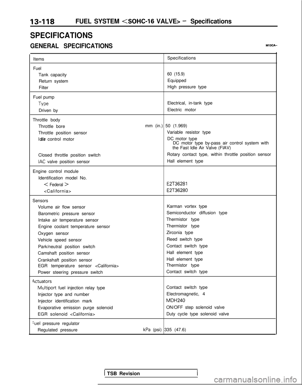
SPECIFICATIONS
GENERAL SPECIFICATIONSMISCA-
Items
Fuel
Tank capacityReturn system
Filter
Fuel pump Type
Driven by
Throttle body Throttle bore
Throttle position sensor Idle air control motor
Closed throttle position switch
IAC valve position sensor
Engine control module Identification model No.
< Federal >
Sensors
Volume air flow sensorBarometric pressure sensor
Intake air temperature sensor
Engine coolant temperature sensor
Oxygen sensor
Vehicle speed sensor
Park/neutral position switch
Camshaft position sensor
Crankshaft position sensor EGR temperature sensor
Power steering pressure switch
Cvctuators
Multiport fuel injection relay type
Injector type and number
Injector identification mark
Evaporative emission purge solenoid
EGR solenoid %el
pressure regulator
Regulated pressure Specifications
60 (15.9)
Equipped
High pressure type
Electrical, in-tank type
Electric motor
mm (in.) 50 (1.969) Variable resistor typeDC motor type DC motor type by-pass air control system with
the Fast Idle Air Valve (FIAV)
Rotary contact type, within throttle position sensor
Hall element type
E2T36281 E2T36280
Karman vortex type
Semiconductor diffusion type
Thermistor type
Thermistor type Zirconia type
Reed switch type
Contact switch type Hall element type
Hall element type
Thermistor type
Contact switch type
Contact switch type
Electromagnetic, 4 MDH240
ON/OFF step solenoid valve Duty cycle type solenoid valve
kPa (psi) 335 (47.6)
1 TSB Revision
Page 269 of 1273
Page 276 of 1273
13-134FUEL SYSTEM (SOHC-16 VALVE> -Service Adjustment Procedures
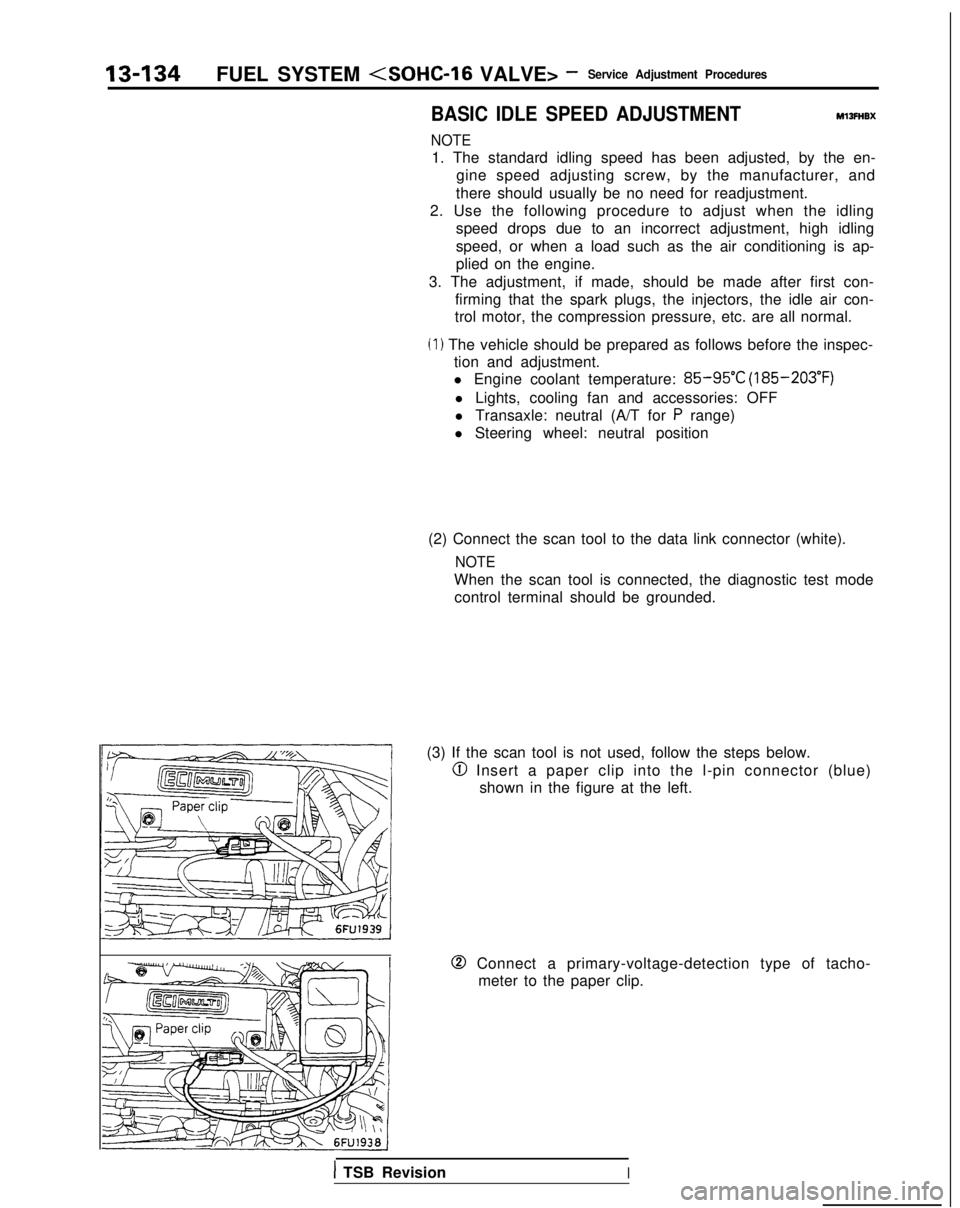
BASIC IDLE SPEED ADJUSTMENTMlIFHBX
NOTE
1. The standard idling speed has been adjusted, by the en-
gine speed adjusting screw, by the manufacturer, and
there should usually be no need for readjustment.
2. Use the following procedure to adjust when the idling speed drops due to an incorrect adjustment, high idling
speed, or when a load such as the air conditioning is ap-
plied on the engine.
3. The adjustment, if made, should be made after first con- firming that the spark plugs, the injectors, the idle air con-
trol motor, the compression pressure, etc. are all normal.
(I ) The vehicle should be prepared as follows before the inspec- tion and adjustment.
l Engine coolant temperature:
85-95°C (185-203°F)
l Lights, cooling fan and accessories: OFF
l Transaxle: neutral (A/T for
P range)
l Steering wheel: neutral position
(2) Connect the scan tool to the data link connector (white).
NOTE
When the scan tool is connected, the diagnostic test mode control terminal should be grounded.
(3) If the scan tool is not used, follow the steps below.
@I Insert a paper clip into the l-pin connector (blue) shown in the figure at the left.
0 Connect a primary-voltage-detection type of tacho-meter to the paper clip.
1 TSB RevisionI
Page 281 of 1273
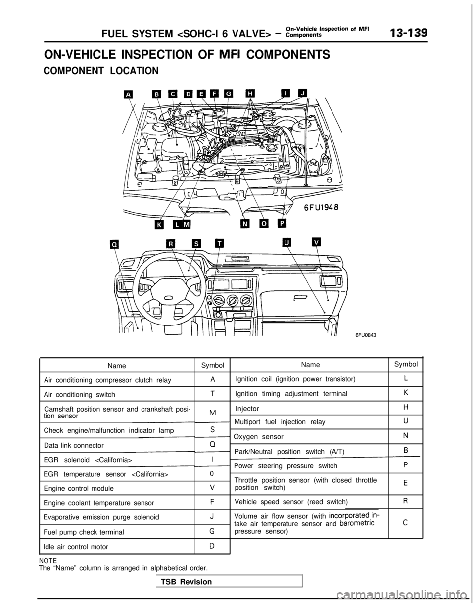
FUEL SYSTEM - ?::;:r%t~pection Of MF’13439
ON-VEHICLE INSPECTION OF MFI COMPONENTS
COMPONENT LOCATION
6FUO843
Name Symbol NameSymbol
Air conditioning compressor clutch relay A
Ignition coil (ignition power transistor)
L
Air conditioning switchTIgnition timing adjustment terminalK
Camshaft position sensor and crankshaft posi- InjectorHMtion sensor- Multiport fuel injection relayU
Check engine/malfunction indicator lampS- Oxygen sensorN
Data link connectorQ- Park/Neutral position switch (A/T)6
EGR solenoid I- Power steering pressure switchP
EGR temperature sensor 0
Throttle position sensor (with closed throttle
position switch)
EEngine control modulev
Engine coolant temperature sensorFVehicle speed sensor (reed switch)R
Evaporative emission purge solenoidJVolume air flow sensor (with incorporated,in-
take air temperature sensor and barometncC
Fuel pump check terminalGpressure sensor)
Idle air control motor
D
NOTEThe “Name” column is arranged in alphabetical order. TSB Revision
Page 317 of 1273
On-Vehicle Inspection of MFI
FUEL SYSTEM - Components
POWER STEERING PRESSURE SWITCH13475
700 - 2,000 (7
- 20,;i~~*~2,000
100 - 284)213- 164)
Pressure
fkPa (kg/on?*. psi11
Enaine control module connector
Enginecontrol
module
Power steering
pressure switch
@ Harness side connector
IIll
7FUO536
I
OPERATION
INSPECTION
Using Scan Tool Refer
to
P.13-82.
7Fuo653
HARNESS INSPECTION
side connector
Engine control
module harness
side connector
I
7FU1235Check for open circuit or short-circuit
to ground, between engine control module and power steering pressure
switch.
l Power steerina messure
switch
connector: Disconnected
l Engine control module connec-
tor: Disconnected
I
Repair the
harness
(@m -11071)
TSB Revision
Page 318 of 1273
13-176FUEL SYSTEM - ::i$%%-ti=pection Of MF’
1
@ Harnesssrde connector
7FUOSO5
Measure the impressed voltage./\1A
l Power steering pressure switch
connector: Disconnected
l Engine control module connec-
tor: Connected
l Ignition switch: ON
Voltage
04
1 modul
e
J
AIR CONDITIONING SWITCH AND A/C COMPRESSOR CLUTCH RELAY
hl13YRABl
ii++----- ,L’AI:
Air conditionino1 switch -
‘A //A\‘A /,,--.l, ,+q‘\
\\Wj i EYAJ26FUO645
Air conditioning
compresso
r
clutch
relav
~-1 6FUO612
Engine control module connector
Sub fusible link
TSB Revision Air conditioning
1
@ m i”“:F$
1
Engine control module ,
I7FUO653
-
,4,
g:2
[
22
Auto compressorcontrol unit
6
2 Dual pressure
I switch 3N
3N
1
1
Air conditioningOFFengine COOlant,^N temperature
2switch
11
5
6FU145.7
OPERATION
TROUBLESHOOTING HINTS INSPECTION
Using Scan Tool Refer
to P.13-83.