Page 835 of 1273

FRONT AXLE - Troubleshooting/Service Adjustment Procedures26-5
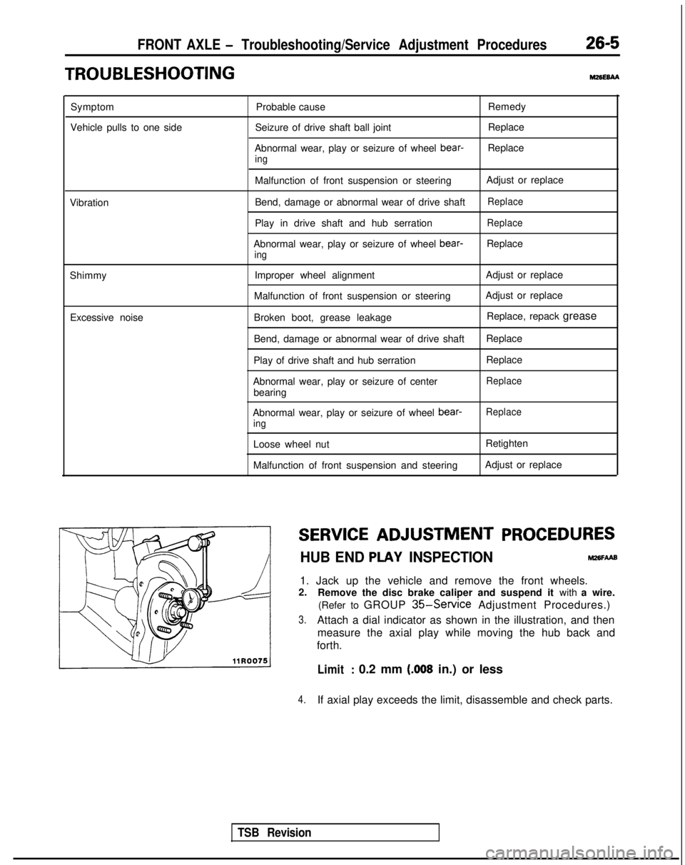
TROUBLESHOOTINGm6E6AA
Symptom
Vehicle pulls to one side Probable cause
Seizure of drive shaft ball joint
Abnormal wear, play or seizure of wheel bear-
ing
Remedy
Replace
Replace
Vibration
Shimmy Excessive noise Malfunction of front suspension or steering
Bend, damage or abnormal wear of drive shaft
Play in drive shaft and hub serration
Abnormal wear, play or seizure of wheel bear-
ing
Improper wheel alignment
Malfunction of front suspension or steering
Broken boot, grease leakage
Bend, damage or abnormal wear of drive shaft
Play of drive shaft and hub serration
Abnormal wear, play or seizure of center bearing Adjust or replace
Replace
Replace
Replace
Adjust or replace
Adjust or replace
Replace, repack grease
Replace
Replace
Replace
Abnormal wear, play or seizure of wheel bear-ing
Loose wheel nut
Malfunction of front suspension and steering
Replace
Retighten
Adjust or replace
SERVICE ADJUSTMENT
PROCEDURES
HUB END PLAY INSPECTIONM26FAAB
1. Jack up the vehicle and remove the front wheels.
2. Remove the disc brake caliper and suspend it with a wire.
(Refer to GROUP
35-Service Adjustment Procedures.)
3.Attach a dial indicator as shown in the illustration, and then measure the axial play while moving the hub back and
forth.
Limit: 0.2 mm (.008 in.) or less
4.If axial play exceeds the limit, disassemble and check parts.
TSB Revision
Page 907 of 1273

32-2POWER PLANT MOUNT - Specifications
SPECIFICATIONS
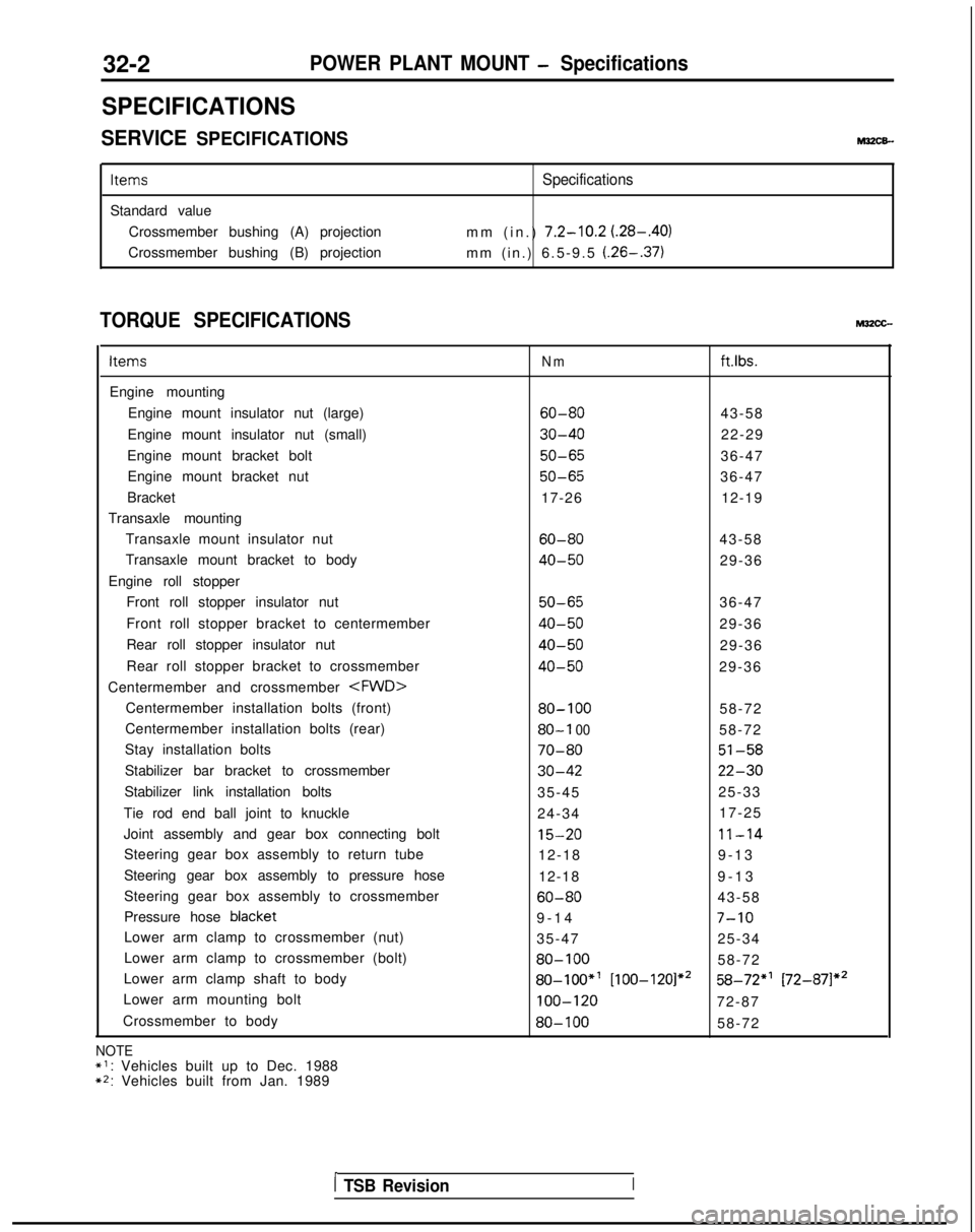
SERVICE SPECIFICATIONSM3ZCE-
Items
Standard value Crossmember bushing (A) projection
Crossmember bushing (B) projection
Specifications
mm (in.) 7.2-10.2 (.28-.40)
mm (in.) 6.5-9.5 (.26-.37)
TORQUE SPECIFICATIONSM32cc-
Items
Engine mounting
Engine mount insulator nut (large)
Engine mount insulator nut (small)
Engine mount bracket bolt Engine mount bracket nut
Bracket
Transaxle mounting Transaxle mount insulator nut
Transaxle mount bracket to body
Engine roll stopper Front roll stopper insulator nut
Front roll stopper bracket to centermember
Rear roll stopper insulator nut
Rear roll stopper bracket to crossmember
Centermember and crossmember
Centermember installation bolts (front)
Centermember installation bolts (rear)
Stay installation bolts
Stabilizer bar bracket to crossmember
Stabilizer link installation bolts
Tie rod end ball joint to knuckle
Joint assembly and gear box connecting bolt Steering gear box assembly to return tube
Steering gear box assembly to pressure hose
Steering gear box assembly to crossmember
Pressure hose blacket
Lower arm clamp to crossmember (nut)
Lower arm clamp to crossmember (bolt)
Lower arm clamp shaft to body
Lower arm mounting bolt
Crossmember to body
NOTE*I: Vehicles built up to Dec. 1988**: Vehicles built from Jan. 1989
Nmftlbs.
60-8043-58
30-4022-29
50-6536-47
50-6536-47
17-26 12-19
60-8043-58
40-5029-36
50-6536-47
40-5029-36
40-5029-36
40-5029-36
80-10058-72
80-I 0058-72
70-8051-58
30-4222-30
35-45 25-33
24-34 17-25
15-2011-14
12-18
9-1
3
12-18 9-13
60-8043-58
9-1
4
7-10
35-47
25-34
80-10058-72
80-loo*’ [100-120]*258-72*’ [72-87]*’
100-12072-87
80-10058-72
1 TSB RevisionI
Page 908 of 1273

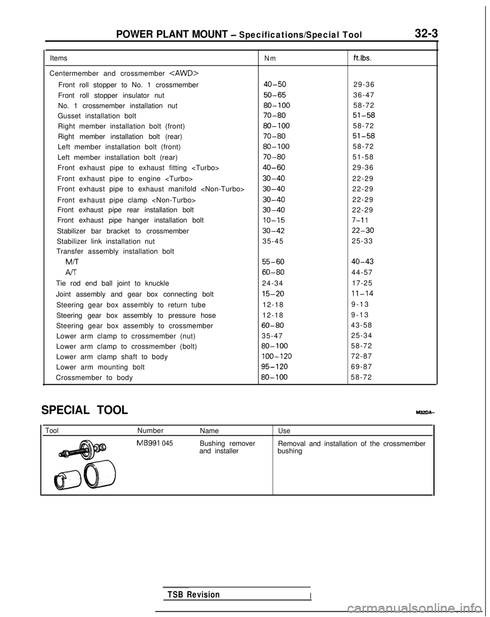
POWER PLANT MOUNT - Specifications/Special Tool32-3
Items
Centermember and crossmember
Front roll stopper to No. 1 crossmember
Front roll stopper insulator nut
No. 1 crossmember installation nut
Gusset installation bolt
Right member installation bolt (front)
Right member installation bolt (rear)
Left member installation bolt (front)
Left member installation bolt (rear)
Front exhaust pipe to exhaust fitting
Front exhaust pipe to engine
Front exhaust pipe to exhaust manifold
Front exhaust pipe clamp
Front exhaust pipe rear installation bolt
Front exhaust pipe hanger installation bolt
Stabilizer bar bracket to crossmember
Stabilizer link installation nut
Transfer assembly installation bolt MIT
Al-r
Tie rod end ball joint to knuckle
Joint assembly and gear box connecting bolt
Steering gear box assembly to return tube
Steering gear box assembly to pressure hose
Steering gear box assembly to crossmember Lower arm clamp to crossmember (nut)
Lower arm clamp to crossmember (bolt)
Lower arm clamp shaft to body
Lower arm mounting bolt
Crossmember to body
Nmftlbs.
40-5029-36
50-6536-47
80-10058-72
70-8051-58
80-10058-72
70-8051-58
80-10058-72
70-8051-58
40-6029-36
30-4022-29
30-4022-29
30-4022-29
30-4022-29
10-157-l 1
30-4222-30
35-45 25-33
55-6040-43
60-8044-57
24-34 17-25
15-2011-14
12-189-1
3
12-18 9-13
60-8043-58
35-47 25-34
80-10058-72
100-12072-87
95-12069-87
80-10058-72
SPECIAL TOOL
ToolNumber
MB991
045
Name
Bushing remover
and installerUse
Removal and installation of the crossmember
bushing
TSB RevisionI
Page 909 of 1273
32-4POWER PLANT MOUNT -Troubleshooting/Engine Mounting
TROUBLESHOOTING
SymptomProbable cause Remedy
Excessive engine wob-
Cracked rubber parts of insulator Replace
ble or vibration (with en-
gine rn normal condition) Insufficiently tightened parts Retighten
Abnormal noise Insufficiently tightened parts Retighten
ENGINE MOUNTING
REMOVAL AND INSTALLATION
.
TSB RevisionI
30-40 Nm22-29 ft.lbs.
Removal steps
Post-installation Operation@Lower the Engine
50-65 Nm36-47 ftlbs.
43-56 ft.lbs.
1. Pressure hose (power steering) and high
pressure hose (air conditioner)
2. BracketOIA0306
3. Engine mount bracket and body connection bolt
4. Engine mount bracket
l + 5. Mounting stopper
INSPECTION
l Check each insulator for cracks or damage
.
l Check each bracket for deformation or damage.
Page 913 of 1273

32-8POWER PLANT MOUNT -Centermember and Crossmember
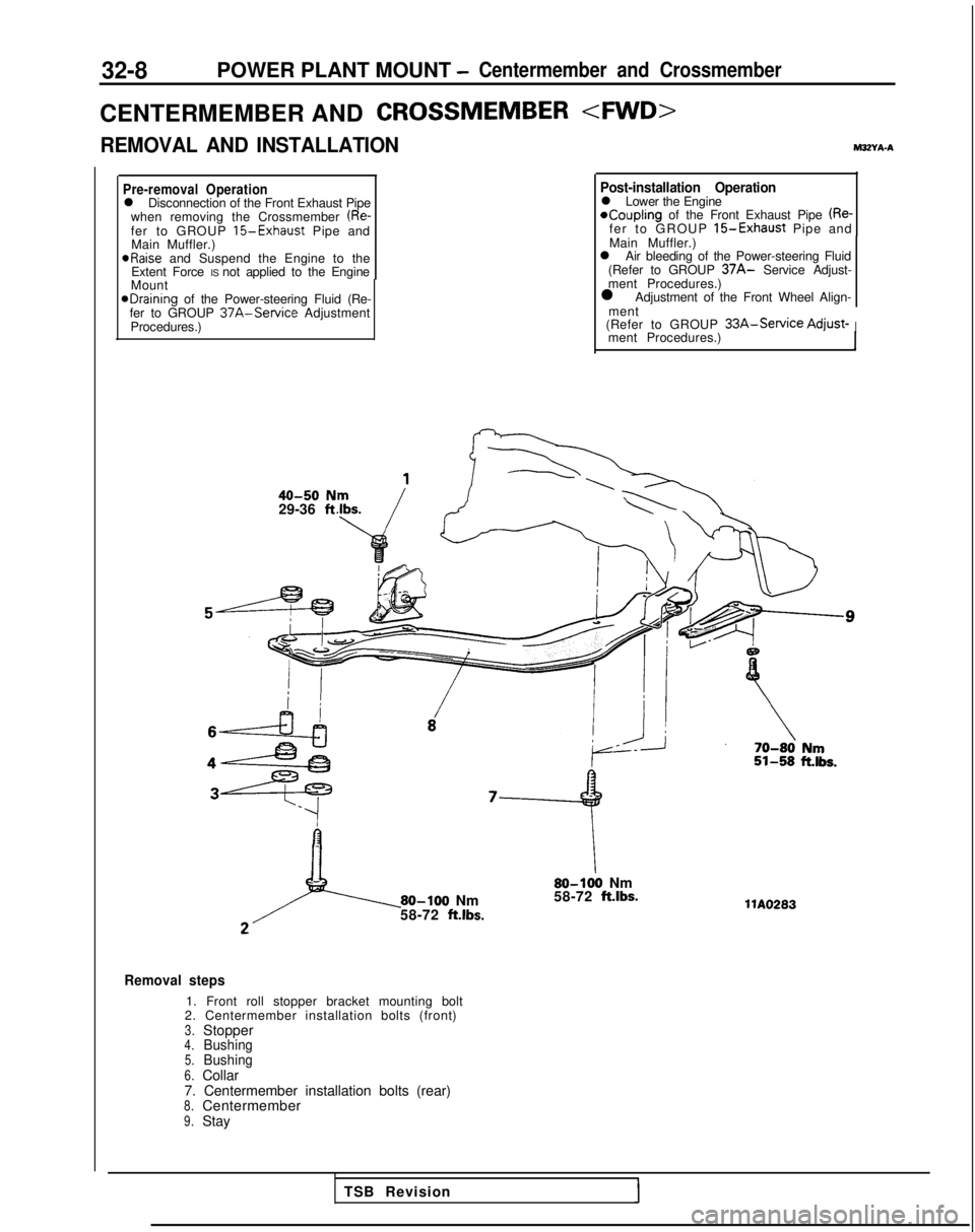
CENTERMEMBER ANDCROSSMEMBER
REMOVAL AND INSTALLATIONM3ZYA-A
Pre-removal Operationl Disconnection of the Front Exhaust Pipe
when removing the Crossmember (Re-fer to GROUP 15-Exhaust Pipe and
Main Muffler.) aRaise
and Suspend the Engine to the
Extent Force IS not applied to the Engine
Mount
@Draining of the Power-steering Fluid (Re-
fer to GROUP 37A-Service Adjustment
Procedures.)
40-50 N29-36 ft
Post-installation Operationl Lower the Engine*Coupling of the Front Exhaust Pipe (Re-fer to GROUP 15-Exhaust Pipe and
Main Muffler.)
l Air bleeding of the Power-steering Fluid
(Refer to GROUP
37A- Service Adjust-
ment Procedures.)
l Adjustment of the Front Wheel Align-
ment
(Refer to GROUP
33A-Service Adjust-Iment Procedures.)
80-100 Nm
58-72 ft.lbs.
80-100 Nm
58-72 ft.lbs.
Removal steps
1. Front roll stopper bracket mounting bolt
2. Centermember installation bolts (front)
3.Stopper4.Bushing5.Bushing6.Collar
7. Centermember installation bolts (rear)
8.Centermember9.Stay llA0283
TSB Revision
Page 914 of 1273
POWER PLANT MOUNT - Centermember and Crossmember32-9
35-45
25-33
14\
SW13 I
e
-22-30 ii.&.15T-\-- .-
30-42
15-20 Nm11-14 ftlbs.18
60-80 Nm43-58 ft.lbs.&dOlA0473
10. Stabilizer link installation nut(Refer to GROUP 33A-Stabilizer Bar.)11. Stabilizer link
12. Stabilizer bar bracket installation bolt
13. Stabilizer bar bracket
14. Bushing
15. Stabilizer bar
(Refer to GROUP 33A-Stabilizer Bar.)
16. Cotter pin
17. Tie-rod end connection nut
18. Joint assembly connection bolt
19. Return tube connection
20. Pressure hose connection
21. Mounting brackets
22. Steering gear box assembly (Refer to GROUP 37A-Steering
Gear
Box.)
TSB Revision1
Page 917 of 1273
32-12POWER PLANT MOUNT -Centermember and Crossmember
C&Et;;rSM>EMBER AND CROSSMEMBER
REMOVAL AND INSTALLATIONM32Yh-0
40-50 Nm29-36 ft.lbs.
50-65 Nm36-47 ft.lbs.80-100
Nm58-72 ftlbs.
80-100
Nm58-72 ft.lbs.
1
’
--
--_ii-58 it.,tTlAO619I 70-r
80 km51-58klbs.
Removal steps
1. Cover installation screw
2.Left member3.Right member
4. Front roll stopper installation bolt
5.No. 1 crossmember installation
nut6.Lower plate7.No. 1 crossmember8.Stopper(B)9.Bushing (B)10.Gusset
Pre-removal OperationeDraining of the Power-steering Fluid
(Refer to GROUP 37A-Service
Adjust-
ment Procedures.)
Post-installation Operation@Air bleeding of the Power-steering Fluid
(Refer to GROUP 37A-Service Adjust-ment Procedures.)l Adjustment of the Front Wheel Align-
ment
(Refer to GROUP 33A-Service Adjust-ment Procedures.)
TSB Revision
Page 919 of 1273