Page 458 of 1273

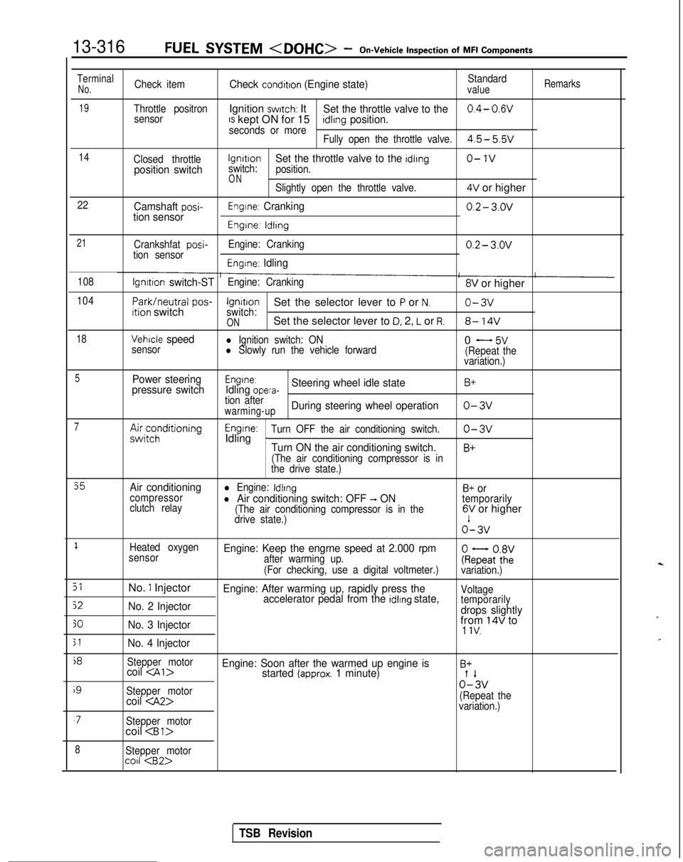
13-316FUEL SYSTEM -On-Vehicle
Inspection
of
MFI
Components
TerminalNo.Check itemCheck condition (Engine state)Standardvalue
Remarks
19Throttle positronIgnition switch: ItSet the throttle valve to the0.4- 0.wsensorIS kept ON for 15seconds or moreidlrng position.
Fully open the throttle valve.4.5- 5.5v
14
Closed throttlelgnrtrono-1vposition switchswitch:Set the throttle valve to the idling
position.
ONSlightly open the throttle valve.4V or higher
22Camshaft posi-tion sensorEngine: Cranking0.2- 3.ov
Engine: ldlrng
21
Crankshfat posi-tion sensor Engine: Cranking0.2- 3.ov
Engine: Idling
108lgnrtion switch-STEngine: Cranking8V or higher
104
Park/neutral
pos-ition switchIgnitionSet the selector lever to P or N.o-3vswitch:ONSet the selector lever to D, 2, L or R.8- 14V
18Vehicle speedl Ignition switch: ON
sensorl Slowly run the vehicle forward0 - 5v(Repeat the
variation.)
5Power steering
pressure switchEngine:Idling opera-Steering wheel idle stateB+
tion afterwarming-upDuring steering wheel operationo-3v
7A&;;;ditioningEngine:Idling _Turn OFF the air conditioning switch.o-3v
Turn ON the air conditioning switch.B+
(The air conditioning compressor is in
the drive state.)
35Air conditioningl Engine: IdlingB+ orcompressor
clutch relayl Air conditioning switch: OFF -, ON(The air conditioning compressor is in the
temporarily
drive state.)6V or higher o’-
3v
1Heated oxygen
sensorEngine: Keep the engrne speed at 2.000 rpmafter warming up.
(For checking, use a digital voltmeter.)ke;atoZivariation.)
51No. 1 InjectorEngine: After warming up, rapidly press the
52No. 2 Injector accelerator pedal from the idlrng state,Voltage
temporarily
drops slightly
30No. 3 Injectorfrom 14V to1 IV.
51No. 4 Injector
j8
Stepper motorcoil Engine: Soon after the warmed up engine isB+started (approx. 1 minute)
i9
Stepper motor0%
coil (Repeat the
variation.)
‘7Stepper motorcoil
8Stepper motorco11
TSB Revision
Page 567 of 1273
COOLING - Water Pump
WATER PUMP REMOVAL AND INSTALLATION14-15
M14MEA
? /’I
50-65 Nm36-47 ft.lbs. a(Refer to GROUP 00-Maintenance
Post-installation Operation*Installation of the Under Cover
*Supplying of the Engine Coolant
(Refer to GROUP 00-MaintenanceService.)aEngine Adjustment
(Refer to GROUP 1 l-Service
Adjustment Procedures.)
/30-40 Nm
22-29 ft.lbs. 14-22
ft.lb=
\
6
03AOl39
Removal steps
I23-27 Nm3IT-20 ft.lbs.
OlAOOlO
I. Clamp part of hoses (Power steering and
air conditioning)
2. Engine mount bracket
3. Drive belt (Air conditioning) (Refer
t0GROUP 00-Maintenance Service.)
4. Drive belt (Power steering) (Refer toGROUP 00-Maintenance Service.)
5. Drive belt (Refer to GROUP OO-Maintenance Service.)
6. Tension pulley bracket
7. Water pump pulley (Power steering)
8. Water pump pulley
9. Damper pulley
TSB Revision1
Page 572 of 1273

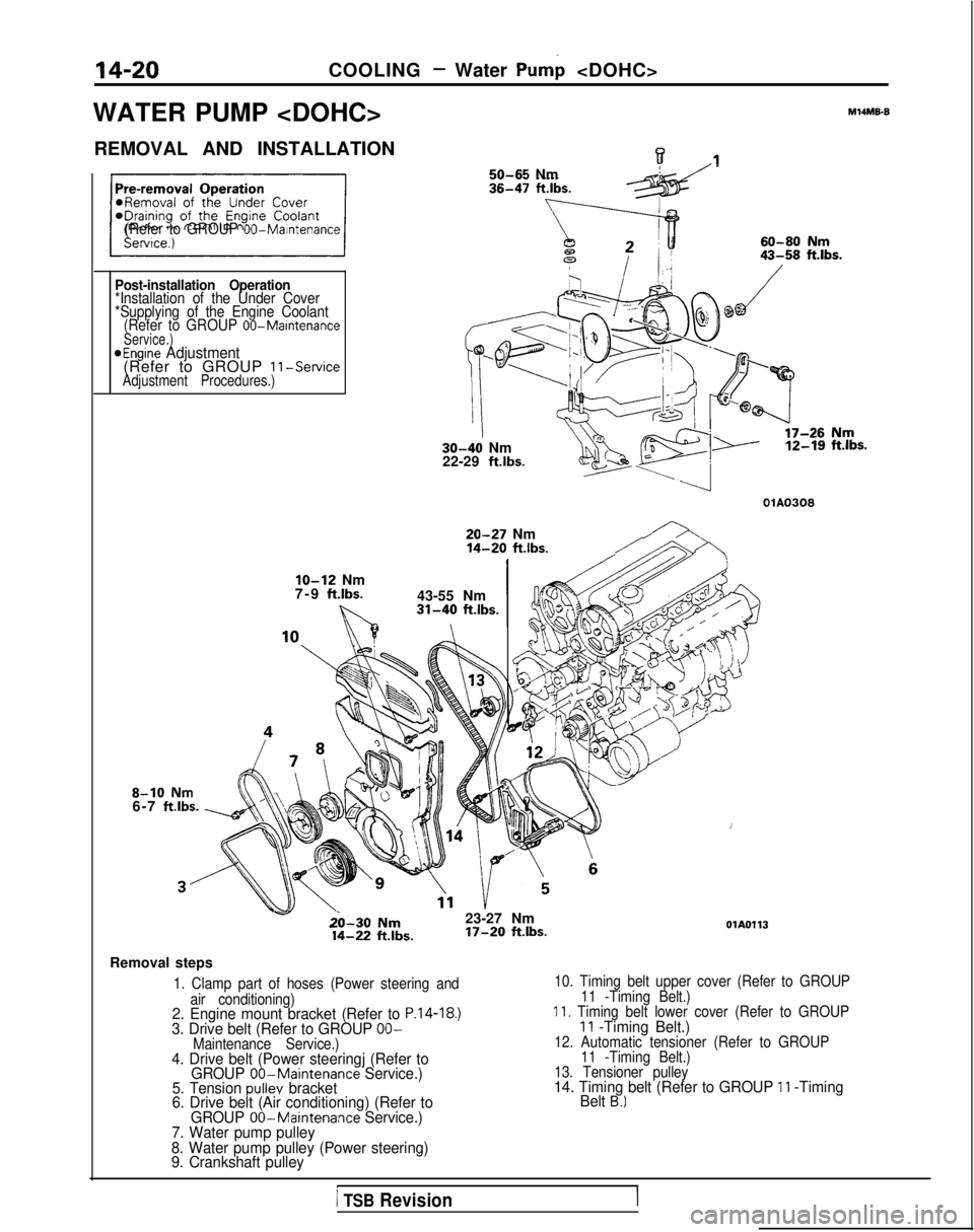
14-20COOLING - Water Pump
WATER PUMP
M14ME6
REMOVAL AND INSTALLATIONw.I50-65 Nm
(Refer to GROUP 00-Maintenance
Post-installation Operation*Installation of the Under Cover
*Supplying of the Engine Coolant (Refer to GROUP
00-MaintenanceService.)aEngine Adjustment(Refer to GROUP 11-ServiceAdjustment Procedures.)
30-40 Nm
22-29 ft.lbs. 12-19
ft.lbs.
OlA0308
20-27 Nm14-20 ft.lbs./
8-10 Nm6-7 ftlbs.
IO-12 Nm
7-9 ft.lbs.
b..
43-55 Nm31-40 ft.lbs.
v&l-30 Nm23-27 Nm 14-22
ftlbs. 17-20
ft.lbs.OlA0113
Removal steps
1. Clamp part of hoses (Power steering and
air conditioning)
2. Engine mount bracket (Refer to P.14-18.)3. Drive belt (Refer to GROUP OO-Maintenance Service.)4. Drive belt (Power steeringj (Refer to GROUP 00-Maintenance Service.)
5. Tension pullev bracket
6. Drive belt (Air conditioning) (Refer to
10. Timing belt upper cover (Refer to GROUP
11 -Timing Belt.)
11. Timing belt lower cover (Refer to GROUP11 -Timing Belt.)12. Automatic tensioner (Refer to GROUP11 -Timing Belt.)
13. Tensioner pulley
14. Timing belt (Refer to GROUP 11 -Timing
Belt B.)
GROUP 00-Maintenance Service.)
7. Water pump pulley
8. Water pump pulley (Power steering)
9. Crankshaft pulley
1 TSB RevisionI
Page 657 of 1273
CLUTCH - Clutch Pedalm-7
CLUTCH PEDAL
REMOVAL AND INSTALLATION
Pre-removal and Post-installation Operation*Removal and Installation of InstrumentUnder Cover
(Refer to GROUP 52-Instrument Panel.)l Removal and Installation of Steering Col-umn Assembly (Refer to GROUP 37A-Steering Wheel and Shaft.)
Adjustmentl Adjustment of Brake Pedal (Refer tcGROUP 35-Service Adjustment Procedures.)@Adjustment of Clutch Pedal
(Refer to P.21-5.)
MZIPA-
2
8-12 Nm
6-9 ft.lbs.
r:-20-25Nmi12Lib-18ft.lbs.*21lo-15 Nm -7-11 ftlbs.
23
24
09AOO79
Semoval steps
1. Return spring
2. Interlock switch
3. Clutch pedal position switch
with auto-cruise control system>
4. Bolt
system>
12. Cotter pin
13. Washer
14. Clevis pin
15. Clutch pedal bracket
16. Pedal suppon bracket
17. Nut
18. Lever
19.Bushing (small)20. Pedal rod
21.
22. Bushing (large)
Clutch pedal23.
Brake pedal
24. Pedal pad
NOTEl ‘: 1989 modelsl *: From 1990 models
TSB Revision
Page 658 of 1273
21-8CLUTCH- Clutch Pedal
Pre-removal and Post-installation Op-eration*Removal and Installation of instrumentUnder Cover
(Refer to GROUP 52-Instrument Panel.)*Removal and Installation of Steering Col-
umn Assembly (Refer to GROUP 37A-
Steering Wheel and Shaft.)
Adjustmentl Adjustment of Brake Pedal (Refer to
GROUP 35-Service Adjustment Proce-dures.)*Adjustment of Clutch Pedal
(Refer to P.21-5.1
3
22
“,24 00AOO82
Removal steps
I. Return spring 14. Clevis pin15. @fch pedal bracket2.Interlock switch3. Clutch pedal position switcn5.Cotter pin6.Washer7.Bushing;: E;;i; pin
;
;: poTrer spring
12.Cotter pin13.Washer 16. Pedal support bracket
17.Nut18.Lever19.Bushing (small)20.Pedal rod21.Bushing (large)22.Clutch pedal23.Brake pedal24.
Pedal pad
TSB Revision
Page 667 of 1273

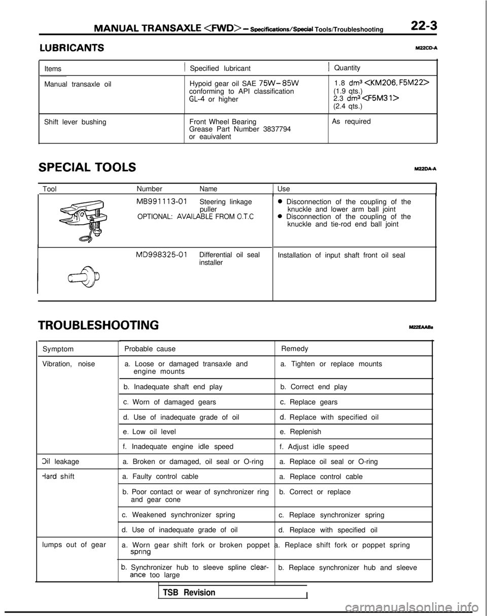
MANUAL TRANSAXLE
- Soec~cations/SpeciI
Tools/Troubleshooting 22-3
LUBRICANTSYZZCD-A
Items1 Specified lubricant1 Quantity
Manual transaxle oil Hypoid gear oil SAE
75W-85Wconforming to API classificationGL-4 or higher1.8
dma
(1.9 qts.)
2.3 dma (2.4 qts.)
Shift lever bushing Front Wheel Bearing
Grease Part Number 3837794
or eauivalent As required
SPECIAL TOOLSWDA-A
Tool
NumberName1 UseI MB991
113-01
Steering linkage
puller
OPTIONAL: AVAIlABLE FROM 0.T.C
MD998325-01Differential oil seal
installer 0
Disconnection of the coupling of the
knuckle and lower arm ball joint 0
Disconnection of the coupling of the
knuckle and tie-rod end ball joint
Installation of input shaft front oil seal
TROUBLESHOOTING
Symptom
Vibration, noise
3il leakage -lard
shift
lumps out of gear Probable cause
Remedy
a. Loose or damaged transaxle and a. Tighten or replace mounts
engine mounts
b. Inadequate shaft end play b. Correct end play
c. Worn of damaged gearsc. Replace gears
d. Use of inadequate grade of oil
d. Replace with specified oil
e. Low oil level e. Replenish
f. Inadequate engine idle speed f. Adjust idle speed
a. Broken or damaged, oil seal or O-ring a. Replace oil seal or O-ring
a. Faulty control cable a. Replace control cable
b. Poor contact or wear of synchronizer ring b. Correct or replace
and gear cone
c. Weakened synchronizer spring c. Replace synchronizer spring
d. Use of inadequate grade of oil d. Replace with specified oil
a. Worn gear shift fork or broken poppet a. Replace shift fork or poppet\
spring spnng
b. Synchronizer hub to sleeve spline
clear-
b. Replace synchronizer hub and sleeveante too large
TSB RevisionI
Page 801 of 1273
AUTOMATIC TRANSAXLE - Transaxle Control23-95
4-6‘Nm3-4 ftlbs.
Pre-removal and Post-installation Operation*Removal and Installation of Console Box Assembly(Refer to GROUP 52-Floor Console.)@Removal and Installation of Instrument Under Cover Assem-
s;bly, Column Cover, Lap Shower Duct and Foot Shower
(Refer to GROUP 5’2-Instrument
Panel.)
9-14 Nm7-10 ftlbs.
4-6 Nm
3-4 ftlbs.
09A0138
Key-interlock cable removal steps
1. Snap pinl +2. Key-interlock cable (selector lever
assembly side)
3. Clamp
4. Cover
I)* 5. Key-interlock cable (steering lock assembly side)
I)+ 6. Slide lever
NOTEBefore connecting the key-interlock cable or the shift-lock
cable, be sure to first connect and adjust the transaxle Shift-lock
cable removal steps
3. Clam
I)+ 7
.
Shift- ock cable
P(selector lever assembly side)
8. Coffer pin
9. Shift-lock cable (brake pdeal side)
control cable.
TSB Revision
Page 803 of 1273

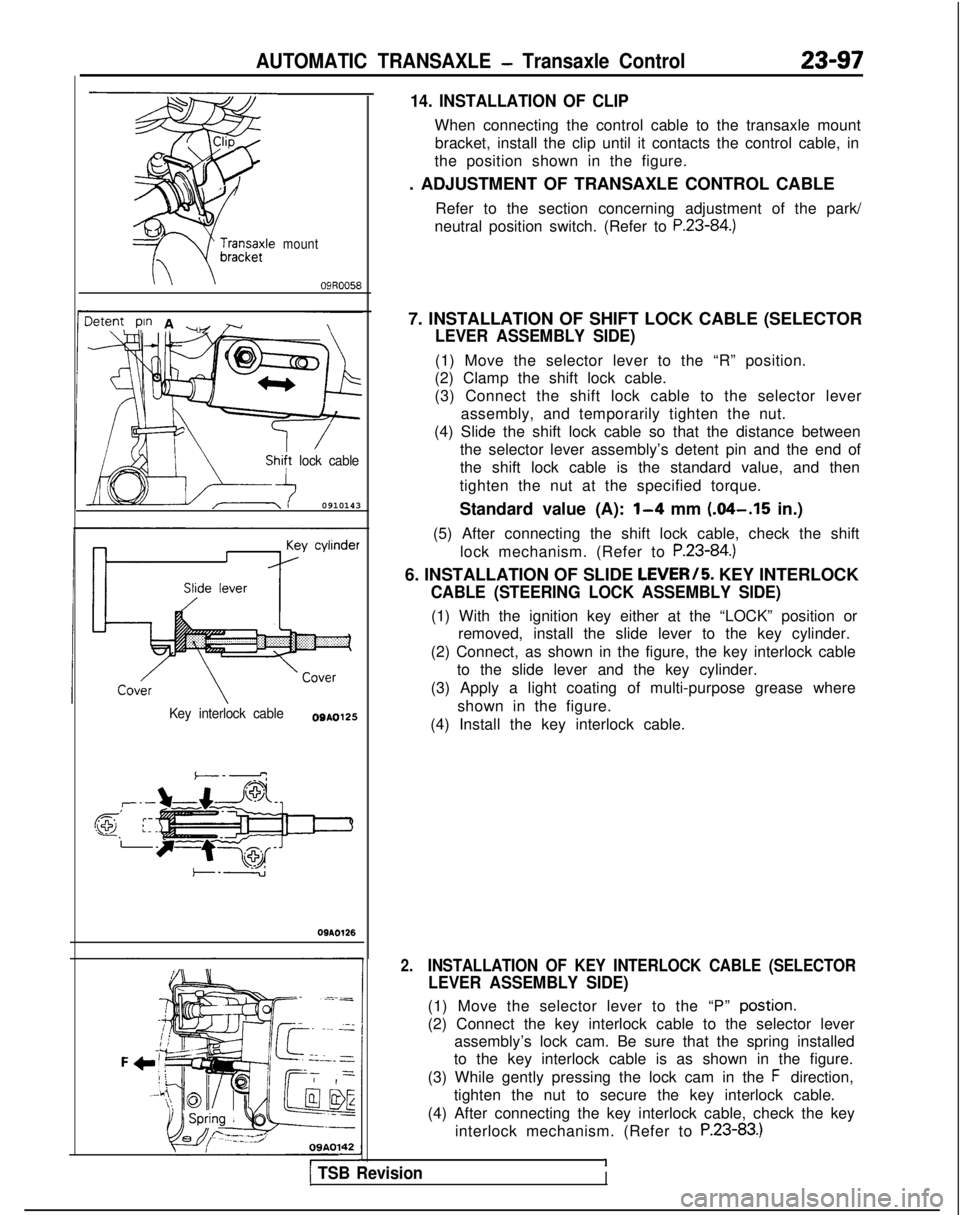
AUTOMATIC TRANSAXLE - Transaxle Control23-97
mount
\09R0058
3tent pin A ~ r\,I, ./
/
lock cable
0910143
Key interlock cableO0A0125
,T’--
@ ;:-.-
09AO126
09A0142
14. INSTALLATION OF CLIP
When connecting the control cable to the transaxle mount
bracket, install the clip until it contacts the control cable, in
the position shown in the figure.
. ADJUSTMENT OF TRANSAXLE CONTROL CABLE
Refer to the section concerning adjustment of the park/
neutral position switch. (Refer to
P.23-84.)
7. INSTALLATION OF SHIFT LOCK CABLE (SELECTOR
LEVER ASSEMBLY SIDE)
(1) Move the selector lever to the “R” position.
(2) Clamp the shift lock cable.
(3) Connect the shift lock cable to the selector lever
assembly, and temporarily tighten the nut.
(4) Slide the shift lock cable so that the distance between the selector lever assembly’s detent pin and the end of
the shift lock cable is the standard value, and then
tighten the nut at the specified torque.
Standard value (A):
1-4 mm (.04-.15 in.)
(5) After connecting the shift lock cable, check the shift lock mechanism. (Refer to
P.23-84.)
6. INSTALLATION OF SLIDE LEVERI5. KEY INTERLOCK
CABLE (STEERING LOCK ASSEMBLY SIDE)
(1) With the ignition key either at the “LOCK” position orremoved, install the slide lever to the key cylinder.
(2) Connect, as shown in the figure, the key interlock cable to the slide lever and the key cylinder.
(3) Apply a light coating of multi-purpose grease where shown in the figure.
(4) Install the key interlock cable.
2.INSTALLATION OF KEY INTERLOCK CABLE (SELECTOR
LEVER ASSEMBLY SIDE)
(1) Move the selector lever to the “P” postion.
(2) Connect the key interlock cable to the selector lever assembly’s lock cam. Be sure that the spring installed
to the key interlock cable is as shown in the figure.
(3) While gently pressing the lock cam in the
F direction,
tighten the nut to secure the key interlock cable.
(4) After connecting the key interlock cable, check the key interlock mechanism. (Refer to
P.23-83.)
11 TSB RevisionI