1989 MITSUBISHI GALANT steering
[x] Cancel search: steeringPage 335 of 1273
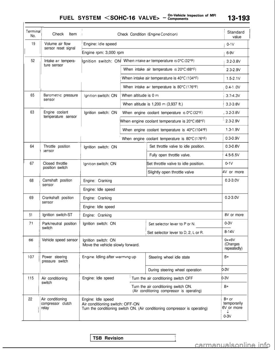
FUEL SYSTEM
TerminaNo.
19
52
-rII
i
t
c
65
L
63
64t
I:
I
Check Item :Check Condition (Engrne Condrtron)
Volume air flowj Engine: Idle speedsensor reset signal
1
Engine rpm: 3,000 rpm
Intake air tempera-1Ignition switch: ON When Intake atr temperature IS 0°C (32°F)ture sensor
When intake air temperature IS 20°C (68°F)
i When intake air temperature is 40°C (104°F)
When intake air temperature is 80°C (176°F)
lgnltlon switch: ON’ When altitude is 0 m
When altitude is 1,200 m (3,937 ft.)
Ignition switch: ON
i When engine coolant temperature IS 0°C (32°F)
When engine coolant temperature is 20°C (68°F)
When engine coolant temperature is 40°C (104°F)
Barometnc pressuresensor
Engine coolant
temperature sensor
Throttle positionsensor
67
68
69
51
115
1
1
Ic22
Closed throttle
position switch
Camshaft position
sensor
Crankshaft position
sensor
Ignition switch-ST
Park/neutral position
switch
Vehicle speed sensor
Power steering
pressure switch
Air conditioning
switch
-I
I When engine coolant temperature is 80°C (176°F)
‘I
) 0.3-0.9v
Ignition switch: ON Set throttle valve to idle position.
0.3-0.6V
iFully open throttle valve.1 4.5-5.5v
Ignition switch: ON
Set throttle valve to idle position.o-1v
’ Slightly open throttle valve4V or more
Engine: Cranking0.2-3.OV
Engine: Idle speed
Engine: Cranking0.2-3.OV
Engine: Idle speed
Engine: Cranking8V or more
Ignition switch: ON
( SetselectorlevertoPorN.o-3v
i Set selector lever to D. 2, L or R.8-14V
Ignition switch: ONi 04d5v
Move the vehicle slowly forward.(Changesrepeatedly)
Engine. Idling after warmrng upSteering wheel idle stateB+
During steering wheel operationo-3v
Engine: Idle speed
’ Turn the air conditioning switch OFFo-3vI
’ Turn the air conditioning switch ON.1 B+(Air conditioning compressor is operating)!
Engine: Idle speed1 B+or
Air conditioning switch: OFF-ONI temporarily
Turn the conditioning switch ON. (Air conditioning compressor is operat\
ing) 1
6V or morej 1
1 o-3v
/ Standard
value
/ o-1v
1 6-9V
1 3.2-3.8V
: 2.3-2.9v
1.5-2.1V
i 0.4-I .ov
j 3.7-4.3v
/ 3.2-3.8V
, 3.2-3.8V
1, 2.3-2.9v
1.3-l .9vI
Air conditioningcompressor clutchrelay
TSB Revision1
Page 338 of 1273
13-196FUEL SYSTEM
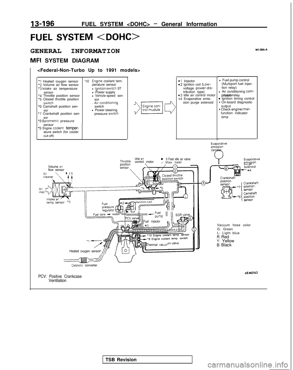
FUEL SYSTEM
GENERAL INFORMATION
MFI SYSTEM DIAGRAMMl
3BA-A
*1 Injector*2 Ignition coil
(Low-
voltage power-drs-
tribution type)
*3 Idle air control motork4 Evaporative emis-
sion purge solenoid l Fuel pump control (Multiport
fuel injec-
tion relay)
l Air conditioning
corm- pressor clutch relay
* Ignition timing control) On-board diagnostic
output
) Check engine/mal-
function indicator
lamp
Engine coolant tem-
perature sensor
l Ignition swatch STl Power supplyl Vehicle-speed sen-sor
. Arr conditioning
switch
l Power steering
pressure
swatch
‘I Heated oxygen sensor ‘10*2
Volume air flow sensor *3
Intake air temperaturesensor‘4 Throttle position sensor *5
Closed throttle position
swrtch *6
Camshaft position sen-
sor “7
Crankshaft position sen-
sor“8 Barometrrc pressure
sensor
‘9 Engine coolant temper-ature switch (for cooler
cut-off)
Evaporatrveemrssion canister
Evaporatrveemlsslo”Idle airThronlecontrol motorl 3 Fast idle air valveI (Wax tvoe)position\Volume air/sensor3flow sensorf \//n,r\l 2 '8
- lnnhnn toll III1 II
II-“,--?% 11 11 EGR,/alveI.l”lll)i
Fuel injectorII
II
Vacuum hose color
G: Green
L: Light blue
I?: RedY: Yellow5: Black
Heated oxygen sensor Thermal
vacuu
a uCatalytrc converter
HMO163PCV: Positive CrankcaseVentilation
TSB Revision
Page 339 of 1273
‘1 Heated oxygen sensor‘2 Volume air flow sensor
“3 intake air temperature
sensor‘4 Throttle position sensor‘5 Closed throttle position
switch
‘6 Camshaft Dosltion sen-
so
r
*7 Crankshaft position sen-sor‘8
Barometnc
pressure
sensor
‘9 Engine coolant temper-
ature switch (for cooler
cut-off)
‘I 0 Knock sensor ‘11
Engien coolant tem-
perature sensor
l Ignition switch STl Power supplyl Vehicle-speed sen-
sor
l Air conditioningswitchl Power steeringpressure switch
Volume airflow sensor \
Idle air
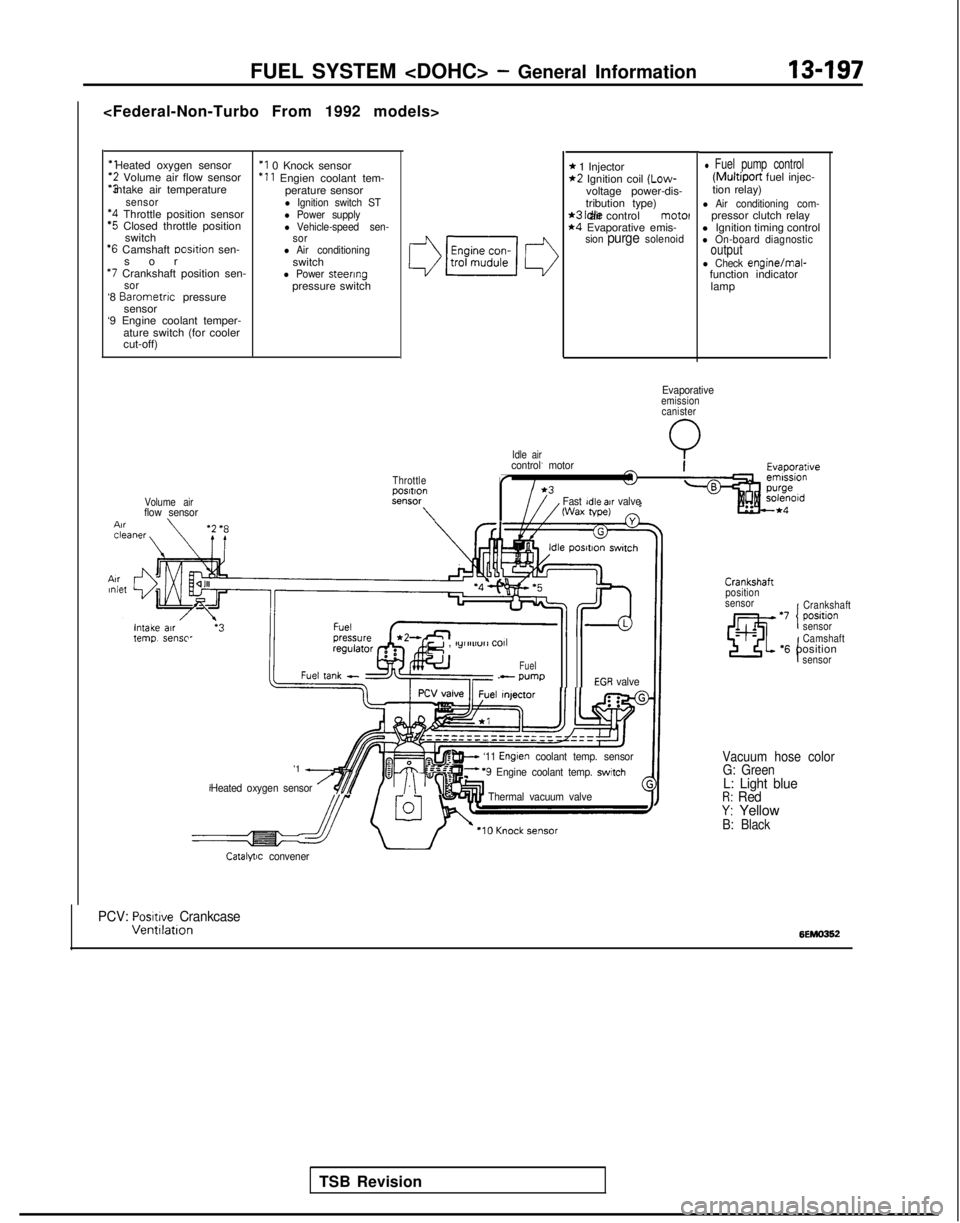
FUEL SYSTEM
* 1 Injector*2 Ignition coil (Low-
voltage power-dis-
tribution type)
*3 Idle air control motel*4 Evaporative emis-sion purge solenoid
l Fuel pump control (Multiport
fuel injec-
tion relay)
l Air conditioning com-pressor clutch relay
l Ignition timing control
l On-board diagnosticoutputl Check engine/mal-
function indicator
lamp
Evaporativeemissioncanister
Q
ThrottlepOSltlOnSt?“SW
\
control motor
r
Fast Idle air valveWax tape)
TSB Revision
e , lylllll”rl
COll
Fuel- wmpEGR valve
'1 A
Heated oxygen sensor /$$y/.\‘“I
w ‘11 Englen coolant temp. sensorF ‘9 Engine coolant temp. switch
Thermal vacuum valve
Crankshaft
position
sensor
‘7 positlon ICrankshaft
sensor
I
Camshaft‘6 positionsensor
Vacuum hose color G: Green
L: Light blueR: RedY: YellowB: Black
Catalytic convener
PCV: Posmve CrankcaseVentllatlon6EMO362
Page 340 of 1273
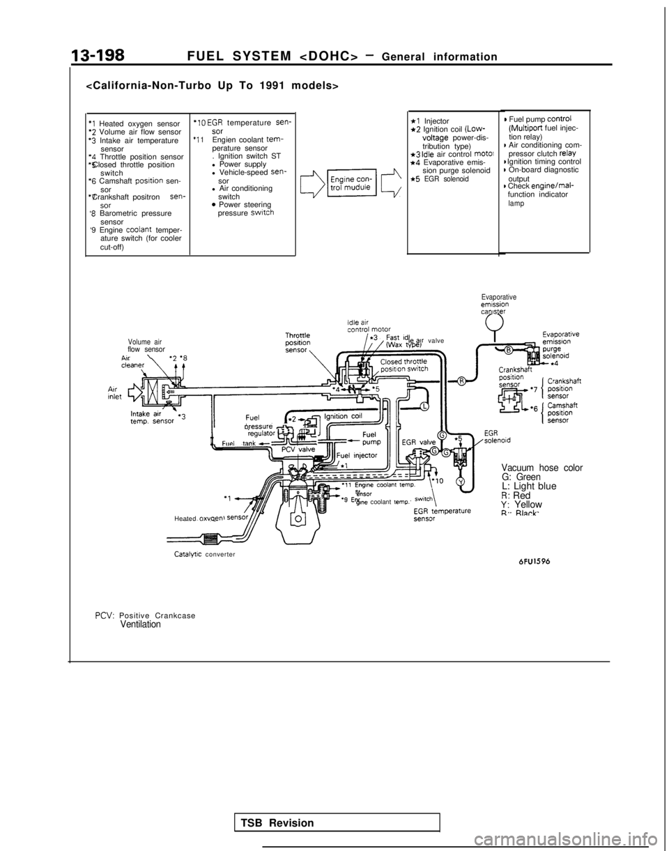
13-198FUEL SYSTEM
*I Heated oxygen sensor *IO
EGR temperature sen-*2 Volume air flow sensor
sor‘3 Intake air temperature
*I 1Engien coolant tem-sensor
perature sensor‘4 Throttle position sensor . Ignition switch ST*5 Closed throttle position
l Power supply
switch l Vehicle-speed sen-
‘6 Camshaft
posltion
sen- sor
sor l Air conditioning“7 Crankshaft positron sen-
switch
SOT0 Power steering‘8 Barometric pressure pressure switch
sensor
‘9 Engine coolant
temper-
ature switch (for cooler
cut-off)
*l Injector*2 Ignition coil (Low-
voltage
power-dis-
tribution type)
*3 idle air control mot01*4 Evaporative emis- sion purge solenoid
*5 EGR solenoid
) Fuel pump control
(Multiport
fuel injec-
tion relay)
I Air conditioning com- pressor clutch relay I Ignition timing control
) On-board diagnostic
output
) Check enginejmal-
function indicator
lamp
Evaporativeemissioncanister
Volume air
flow sensorA..\
II
oressure db,Fun, taw”l”‘“‘~
Heated 0~““~” le
ax valve
e”SOrgme coolant temp.
Vacuum hose color
G: Green
L: Light blueR: RedY: YellowR. Rlnrk
Catalytic converter 6FU1596
PCV:
Positive Crankcase
Ventilation
TSB Revision
Page 341 of 1273
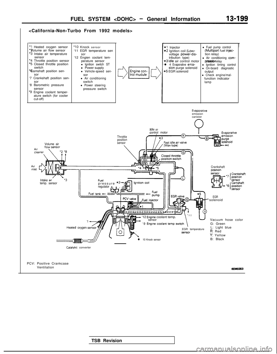
FUEL SYSTEM
*1 Heated oxygen sensor *2 Volume air flow sensor
‘3 Intake air temperature
sensor *4
Throttle position sensor
‘5 Closed throttle position
switch *6 Camshaft position sen-
sor
‘7 Crankshaft position sen- sor
‘8 Barometric pressure
sensor
‘9 Engine coolant temper-ature switch (for cooler
cut-off)
Volume air
‘10 Knock sensor
‘11 EGR temperature sen
sor‘12 Engien coolant tem- perature sensor
l Ignition switch STl Power supplyl Vehicle-speed sen-sorl Air conditioningswitchl Power steeringpressure switch
3
Throttleposition
sensor
IIntake air.‘3Fueltemp. sensorpressure *2-regulatorA-
-
.
cd
’
*l Injectorl Fuel pump control*2 Ignition coil (Low- (Multiport
fuel injec-voltage power-dis-
tion relay)
tribution type)
*3 Idle air control motorl Air conditioning com-
l 4 Evaporative emis- pressor clutch relaysion purge solenoidl Ignition timing control
t5 EGR solenoidl On-board diagnosticoutputl Check engine/mal-function indicatorlamp
Idle
aircontrol motorI Wax
wei
I
I
TSB Revision
Evaporativeemission
canister
Heared oxygen
It=
‘12 Engine coolant temp.sensor-‘I u
‘9 Engine coolant temp switch\
l 10 Knock sensor
EGR temperature
Crankshaftposltlon
EGR‘solenoid Vacuum hose colorG: GreenL: Light blue
R: RedY: Yellow
B: Black
Catalfllc converter
PCV: Positive Crankcase Ventilation
Page 342 of 1273
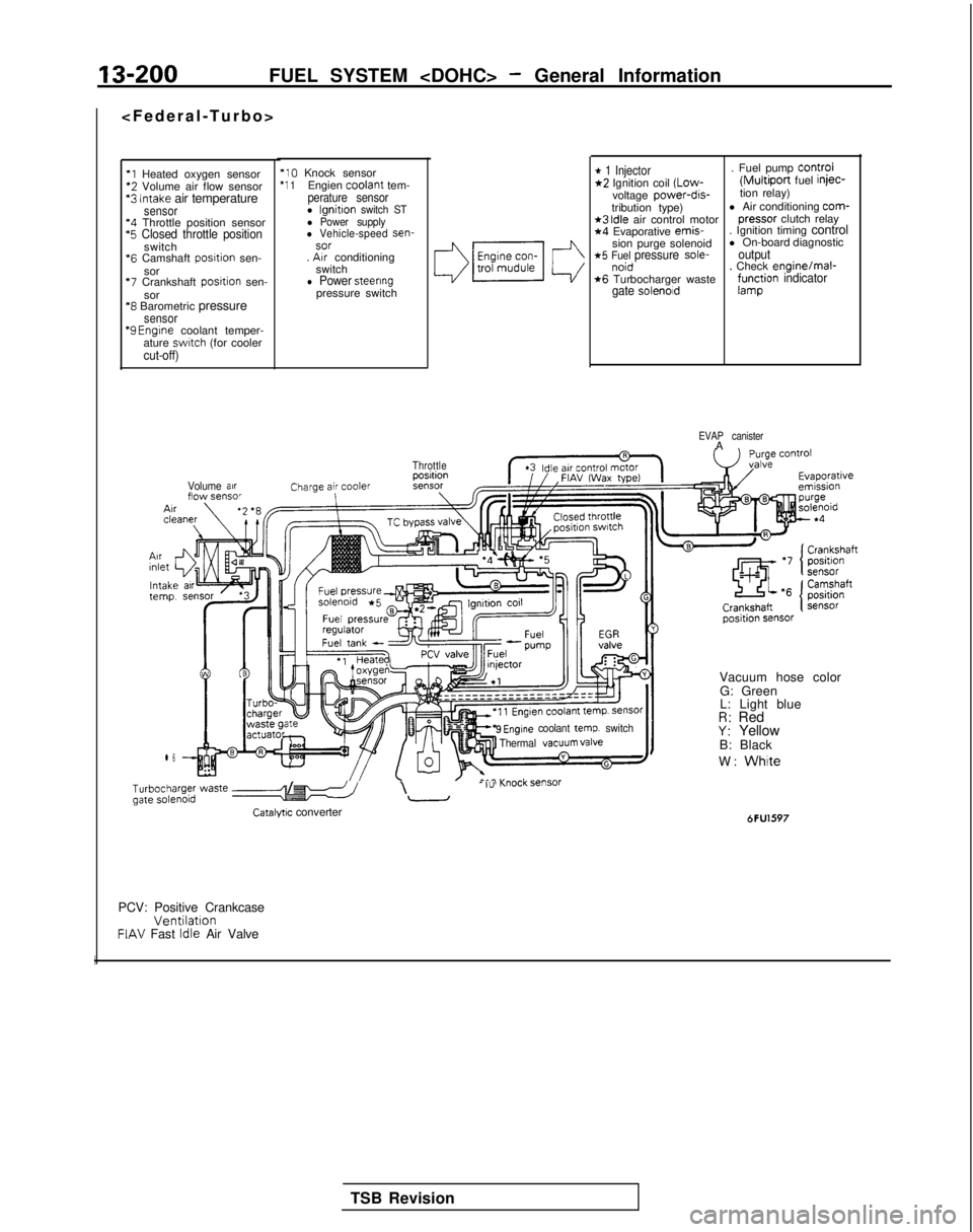
13-200FUEL SYSTEM
*l Heated oxygen sensor‘2 Volume air flow sensor*3 Intake air temperaturesensor‘4 Throttle position sensor‘5 Closed throttle positionswitch
*6
Camshaft posrtion sen-
sor
‘7 Crankshaft posrtion sen-
sor
‘8 Barometric pressuresensor “9
Engrne coolant temper-
ature swatch (for coolercut-off)
‘10 Knock sensor‘1 1Engien coolant
tem-perature sensorl lgnitton switch STl Power supplyl Vehicle-speed sen-sor. Arr conditioning
switch
l Power steeringpressure switch
Volume arrflow sensor
l 6
* 1 Injector. Fuel pump Control*2 Ignition coil (Low-(Multiport fuel injec-
voltage power-dis-tion relay)
tribution type) l Air conditioning com-
*3 Idle air control motor
pressor
clutch relay*4 Evaporative emis-
. Ignition timing control
sion purge solenoid l On-board diagnostic
*5 Fuel pressure sole-outputnoid. Check enginelmal-*6 Turbocharger wastegate solenoidf;r$ion indicator
EVAP canisterA
Throttle
9 Engine coolant temp. switch
Thermal VaCUUm valve
b;~ype; waste e-5 /I\- I”-
Catalyw converter
Vacuum hose color
G: Green
L: Light blue
R: RedY: Yellow
B: Black
W:
White
6FU1597
PCV: Positive CrankcaseVentilationFIAV Fast Idle Air Valve
I
TSB Revision
Page 343 of 1273
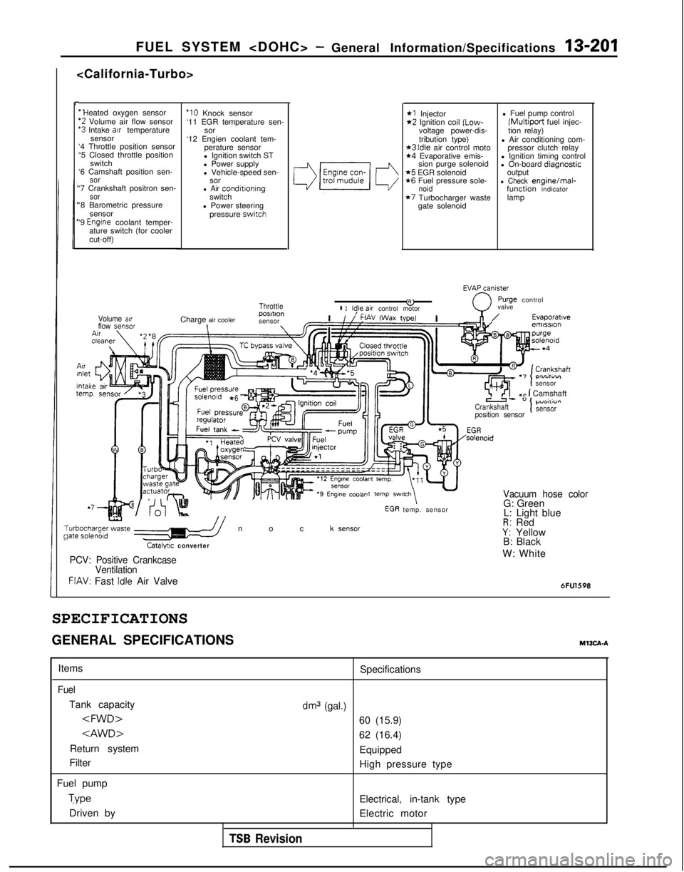
FUEL SYSTEM
I-
‘1 Heated oxygen sensor
‘2 Volume air flow sensor‘3 Intake arr temperature
sensor
‘4 Throttle position sensor
“5 Closed throttle position
switch
‘6 Camshaft position sen-
sor‘7 Crankshaft positron sen-sor‘8 Barometric pressure
sensor
‘9
Engrne coolant temper-
ature switch (for cooler
cut-off)
ArrInlet
lntaltern1
Volume airflow sensor
‘IO Knock sensor
‘11 EGR temperature sen- sor
‘12 Engien coolant tem- perature sensor
l Ignition switch ST
l Power supply
l Vehicle-speed sen- sor
l Air conditroningswitch
l Power steering pressure
swatch
Throttle
Charge air cooler posmon
sensor\\
*I Injector*2 Ignition coil (Low-
voltage power-dis-
tribution type)
*3 Idle air control moto*4 Evaporative emis- sion purge solenoid
*5 EGR solenoid*6 Fuel pressure sole-noid*7 Turbocharger waste
gate solenoid l Fuel pump control
(Multiport fuel injec-
tion relay)
l Air conditioning com- pressor clutch relay
l Ignition timing control
l On-board diaanostic
output
-l Check enginelmal-
function indicator
lamp
EVAxniy
&0
rurge controll 3ld,le,~ir control motor valve
,n/Evaporatrveemrssron
\tcln-^- temp. sensor
,Ir I-, . -,
sensor
7 ’ <‘I+c 1 Camshaft
Crankshaft1p”3111”I I
position sensorsensor
it
temp SWl,Ch\ -Vacuum hose color
t
WV:0 Knock sensor$bgha;ge;zte //
Catalyuc converter
G: Green
L: Light blue
R: RedY: Yellow
B: Black
PCV: Positive Crankcase
VentilationW: White
FIAV: Fast Idle Air Valve6FU1598
SPECIFICATIONS
GENERAL SPECIFICATIONSM13CA-A
Items
Fuel
Tank capacity
Return system
Filter
Fuel pump Type
Driven by Specifications
dm3 (gal.)
60 (15.9)
62 (16.4)
Equipped
High pressure type
Electrical, in-tank type
Electric motor
TSB Revision
Page 344 of 1273
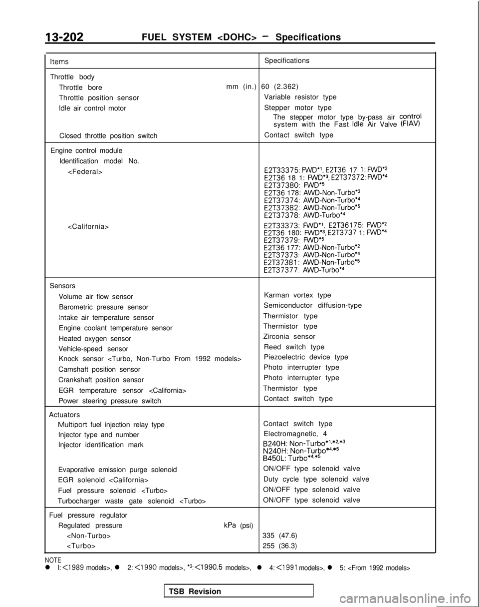
13-202FUEL SYSTEM
Throttle body Throttle bore
Throttle position sensor idle
air control motor
Closed throttle position switch
Engine control module Identification model No.
mm (in.) 60 (2.362) Variable resistor type
Stepper motor type The stepper motor type by-pass air COntrOl
system with the Fast
Idle Air Valve (FIAV)
Contact switch type E2T33375:
FWD”,
E2T36 17 1: FWD’2E2T36 18 1: FWD.3, E2T37372: FWDe4 E2137380:
FWDa5E2T36 178: AWD-Non-Turbo’2 E2T37374:
AWD-Non-Turboe4 E2T37382:
AWD-Non-Turbo*5 E2T37378:
AWD-Turbo’4 E2T33373:
FWD”.
E2T36175: FWDe2E2T36 180: FWD’3, E2T3737 1: FWDa4 E2T37379:
FWD’SE2T36 177: AWD-Non-Turbo’2 E2T37373:
AWD-Non-Turbo’4 E2T37381:
AWD-Non-Turbo’5 E2T37377:
AWD-Turbo*4
Sensors
Volume air flow sensor Karman vortex type
Barometric pressure sensor Semiconductor diffusion-type
Intake air temperature sensor
Thermistor type
Engine coolant temperature sensor Thermistor type
Heated oxygen sensor Zirconia sensor
Vehicle-speed sensor Reed switch type
Knock sensor
Camshaft position sensor Photo interrupter type
Crankshaft position sensor Photo interrupter type
EGR temperature sensor
Power steering pressure switch Contact switch type
Actuators
Multiport fuel injection relay type Contact switch type
Injector type and number Electromagnetic, 4
Injector identification mark B240H:
Non-Turbo*1**2.*3
N240H:
Non-Turbo*4,*5B450L: Turbo*4**5
Evaporative emission purge solenoid ON/OFF type solenoid valve
EGR solenoid
Fuel pressure solenoid
Turbocharger waste gate solenoid
Fuel pressure regulator Regulated pressure
kPa (psi)
NOTEl l: <1989 models>, l 2: <1990 models>, ‘3: <1990.5 models>,l 4:
<1991 models>, l 5:
TSB Revision