1989 MITSUBISHI GALANT steering
[x] Cancel search: steeringPage 76 of 1273
Cyl1n&r’ ;;(oozhead
Sealant: 3M
ATD Part No.8660
or equivalent 5-7
Nm4-5 ft.lbs 90-100
Nm65-72 ftlbs.
40-50 Nm /29 - 36 ft.lbs.
30-40 Nm22- 29
ftlbs.
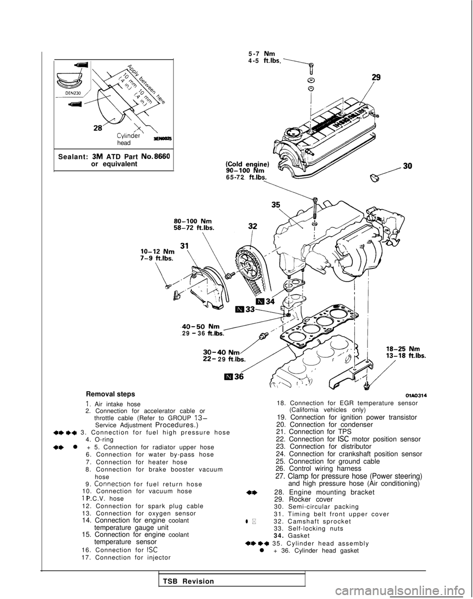
Removal steps
I. Air intake hose
2. Connection for accelerator cable or
throttle cable (Refer to GROUP
13-Service Adjustment Procedures.)+e +a 3. Connection for fuel high pressure hos
e
4. O-ring
+e l + 5. Connection for radiator upper hose
6. Connection for water by-pass hose
7. Connection for heater hose
8. Connection for brake booster vacuum
hose
9.
Connectron for fuel return hos
e
10. Connection for vacuum hose 11. P.C.V. hose
12. Connection for spark plug cable
13. Connection for oxygen sensor
14. Connection for engine coolant temperature gauge unit
15. Connection for engine coolant
temperature sensor
16. Connection for
ISC17. Connection for injector
olAo314
l *
18. Connection for EGR temperature sensor (California vehicles only)
19. Connection for ignition power transistor
20. Connection for condenser
21. Connection for TPS
22. Connection for
ISC motor position sensor
23. Connection for distributor
24. Connection for crankshaft position sensor
25. Connection for ground cable
26. Control wiring harness
27. Clamp for pressure hose (Power steering)and high pressure hose (Air conditioning)
28. Engine mounting bracket
29. Rocker cover
30. Semi-circular packing
31. Timing belt front upper cover
32. Camshaft sprocket 33. Self-locking nuts
34. Gasket
+e ++ 35. Cylinder head assembl
y
l + 36. Cylinder head gasket
TSB Revision
Page 84 of 1273
11-34
ENGINE
TIMING BELT (8 VALVE>MIlKA-A
REMOVAL AND INSTALLATION
Pre-removal OperationaRemoval of under cover 50-65
Nm
36-47 ftlbs.
\ 22-29
ft.lbs.
ft.lbs.
IO-12 Nm
7-9 ft.lbs. 10
m\../.8-10 N6-7 ft.lbs.\
20-30 N,/ v \R \OlAO43414-22 ft.lbs. \I3
10-12’
Nm7-S ftlbs.
6
23-27 Nm 17-20
ft.lbs.
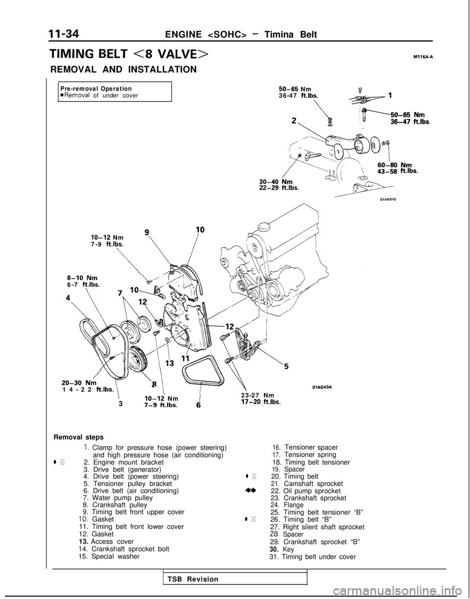
Removal steps
1. Clamp for pressure hose (power steering)
and high pressure hose (air conditioning)
l *2. Engine mount bracket
3. Drive belt (generator)
4. Drive belt (power steering)
5. Tensioner pulley bracket
6. Drive belt (air conditioning)
7. Water pump pulley
8. Crankshaft pulley
9. Timing belt front upper cover
10. Gasket
11. Timing belt front lower cover
12. Gasket
13. Access cover
14. Crankshaft sprocket bolt
15. Special washer
16.Tensioner spacer17.Tensioner spring
18. Timing belt tensioner
19.Spacerl *20. Timing belt21.Camshaft sprocket*‘I)22. Oil pump sprocket23.24.Crankshaft sprocketFlange25. Timing belt tensioner “B”l *26. Timing belt “B”
27. Right silent shaft sprocket
28.Spacer29. Crankshaft sprocket “B”30.Key31. Timing belt under cover
TSB Revision
Page 85 of 1273
ENGINE
IPost-installation Operationl installation of under coverIaService Adjustment Procedures
(Refer to P.ll-7.)I 50-60
Nm36-43 ftlbs.
31
\\15-22 Nm
11-16 ft.lbs. 24
01 A0437
30. KevIL. -I"..--+A ‘IIT:m;nn halt fmnf lower cover
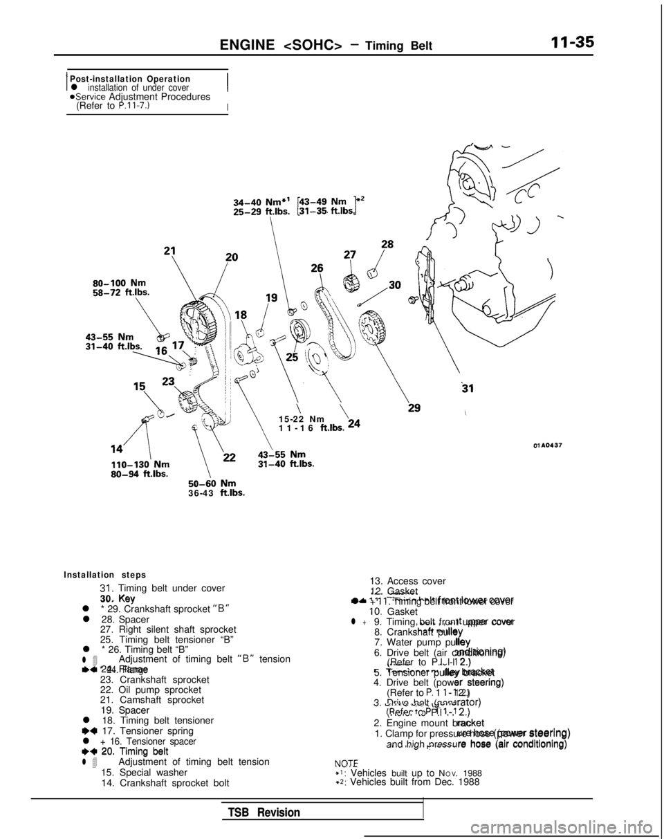
Installation steps
31. Timing belt under cover
30. Key
l * 29. Crankshaft sprocket
“B”l 28. Spacer 27. Right silent shaft sprocket
25. Timing belt tensioner “B”
l * 26. Timing belt “B”
l 4Adjustment of timing belt “B” tensionl * 24. Flange23. Crankshaft sprocket
22. Oil pump sprocket
21. Camshaft sprocket
19. Spacer
l 18. Timing belt tensioner
~~ 17. Tensioner springl + 16. Tensioner spacer++ 20. Timing beltl 4Adjustment of timing belt tension
15. Special washer 14. Crankshaft sprocket bolt
tic 24. Flanae
, UtiIL , , WI ,t upper cover!hcaft n, dlqy
lb. :;d)rtroning)
\..“.w.
.-c
T-mrinnar r
nliny bracket
er steering)1 2.)
19. Spacer
++ 20. Timing belt13. Access cover
12. Gasket
l +
11. Timing belt front lower cover10. Gasketl +9. Timing belt front upper cover 8. Crankshaft pulley
7. Water pump pulley
6. Drive belt (air conditioning) (Refer to P.l l-l 2.)
5. Tensioner pulley bracket
4. Drive belt (power steering)
(Refer to
P. 1 l-l 2.)
3. Drive belt (generator) (Refer to P.l l-l 2.)
2. Engine mount bracket 1. Clamp for pressure hose (power steering)
and high pressure hose (air conditioning)
NOTE*I: Vehicles built up to N O
V. 1988
+2: Vehicles built from Dec. 1988 lrator)
U. Vll”” ““SC \y”v’ulRpfcw tn P 1 l-l
2.)
racket
NOT=
ure hose (power steering)
s-4, I” I “..J’I p.. .#““.are hose (air conditioning)
TSB Revision
TSB Revision
Page 92 of 1273
11-42
ENGINE
TIMING BELT
REMOVAL AND INSTALLATION
MIlKA-A
Pre-removal Operation
l Removal of under cover
8-10 Nm6-7 ftlbs.
4
’‘\ 50-65
Nm
36-47
ft.lbs.\
IO-12 Nm7-9 ftlbs.
\
\
ft.lbs.’3Q ’23-27 Nm
17-20 ft.lbs.
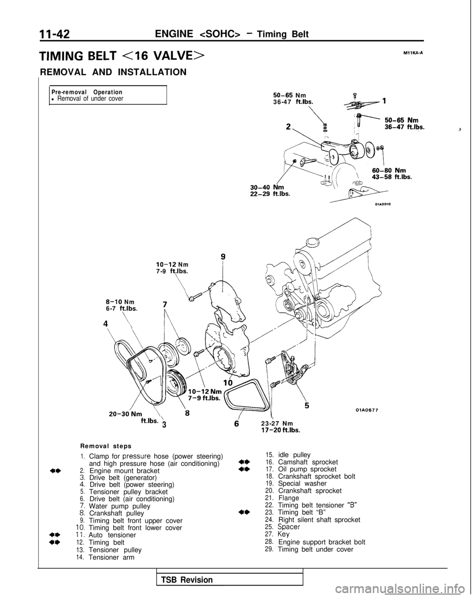
Removal steps
1.
2.
Clamp for
pressure
hose (power steering)
and high pressure hose (air conditioning) Engine mount bracket
Drive belt (generator) Drive belt (power steering)
Tensioner pulley bracket Drive belt (air conditioning)
Water pump pulley Crankshaft pulley
Timing belt front upper cover
Timing belt front lower cover
Auto tensioner
Timing belt OlA0677
::5.6.
i:9.10.11.
12.
13.14.Tensioner pulley
Tensioner arm
15.
::16.
17.
18.
19.
20.
21.
22.
4*23.
24.
25.
27.
28.
29.
idle pulley
Camshaft sprocket
Oil pump sprocket
Crankshaft sprocket bolt
Special washer Crankshaft sprocket
FlangeTiming belt tensioner “B”
Timing belt “B”
Right silent shaft sprocket Spacer
Kky
Engine support bracket bolt
Timing belt under cover
P
TSB Revision
Page 93 of 1273
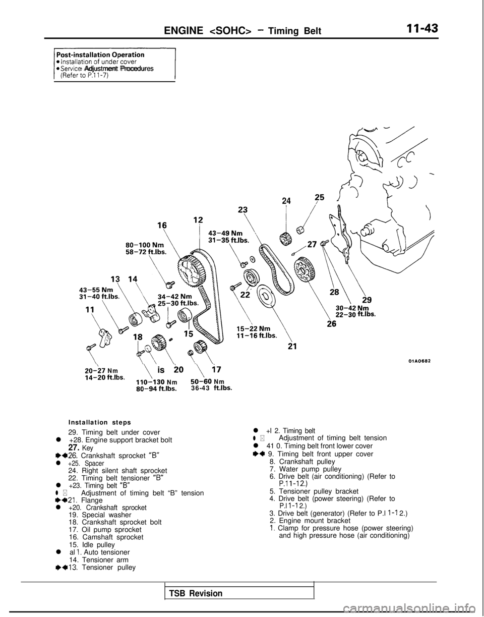
ENGINE
+/@Service Adjustment Procedures
24?5
20-;7 Nmio
14-20 ft.lbs.\ is\ i7
Nm50-60 Nm80-94 ft.lbs.36-43 ft.lbs.
Installation steps
29. Timing belt under cover
l +28. Engine support bracket bolt
27. Keyea26. Crankshaft sprocket “6”l +25. Spacer24. Right silent shaft sprocket
22. Timing belt tensioner “B”
l +23. Timing belt
“B”l *Adjustment of timing belt “B” tension1)421. Flangel +20. Crankshaft sprocket19. Special washer
18. Crankshaft sprocket bolt
17. Oil pump sprocket
16. Camshaft sprocket
15. Idle pulley
l al
1. Auto tensioner
14. Tensioner arm 1)+13.
Tensioner pulley
ftlbs.
OlAO682
l +I 2. Timing beltl *Adjustment of timing belt tension
l 41 0. Timing belt front lower cover
I)+ 9. Timing belt front upper cover 8. Crankshaft pulley
7. Water pump pulley
6. Drive belt (air conditioning) (Refer to
P.ll-12.)5. Tensioner pulley bracket
4. Drive belt (power steering) (Refer to
P.l l-l 2.)3. Drive belt (generator) (Refer to P.l l-l 2.)
2. Engine mount bracket
I. Clamp for pressure hose (power steering) and high pressure hose (air conditioning)
TSB Revision
Page 104 of 1273
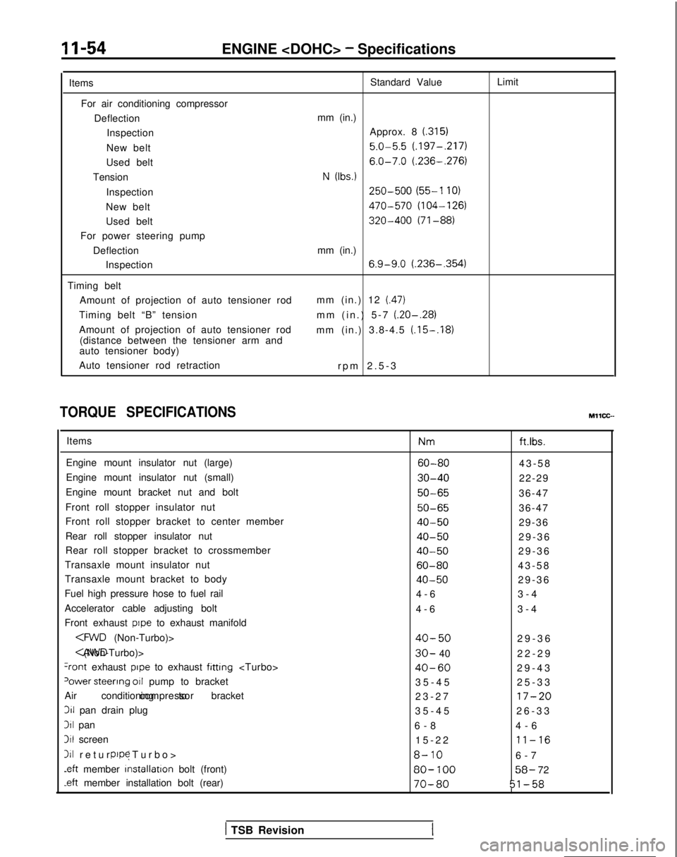
11-54ENGINE
Items For air conditioning compressor DeflectionInspection
New belt
Used belt
Tension
Inspection
New belt
Used belt
For power steering pump
DeflectionInspection
Timing belt Amount of projection of auto tensioner rod
Timing belt “B” tension
Amount of projection of auto tensioner rod (distance between the tensioner arm and
auto tensioner body)
Auto tensioner rod retraction Standard Value
mm (in.) Approx. 8
(.315)
5.0-5.5 (.197-,217)
6.0-7.0 (.236-.276)
N (Ibs.)
250-500 (55-l 10)
470-570 (104-126)
320-400 (71-88)
mm (in.)
6.9-9.0 (.236-,354)
mm (in.) 12 (.47)
mm (in.) 5-7 (.20-.28)
mm (in.) 3.8-4.5 (.15-.18)
rpm 2.5-
3
Limit
TORQUE SPECIFICATIONS
Items
Engine mount insulator nut (large)
Engine mount insulator nut (small)
Engine mount bracket nut and bolt
Front roll stopper insulator nut
Front roll stopper bracket to center member
Rear roll stopper insulator nut
Rear roll stopper bracket to crossmember
Transaxle mount insulator nut
Transaxle mount bracket to body
Fuel high pressure hose to fuel rail
Accelerator cable adjusting bolt
Front exhaust
pope to exhaust manifold
+ont exhaust pope to exhaust fitting
‘ower steerrng 011 pump to bracket
Air conditioning to bracket compressor311
pan drain plug
311 pan
3il screen
111 return (Turbo
>
pope
.eft
member installation
bolt (front)
-eft member installation bolt (rear) Nm
ft.ibs.
60-8043-5
8
30-4022-29
50-6536-47
50-6536-47
40-5029-36
40-5029-3
6
40-5029-3
6
60-8043-5
8
40-5029-3
6
4-6 3-4
4-6 3-4
40-5029-3
6
30- 40
22-2
9
40-6029-4
3
35-45 25-33
23-27
17-20
35-4
5
26-33
6-8 4-6
15-22
11-16
8-106-
7
80-
10058- 72
70-8051-58
MllCC--
( TSB Revision
Page 108 of 1273
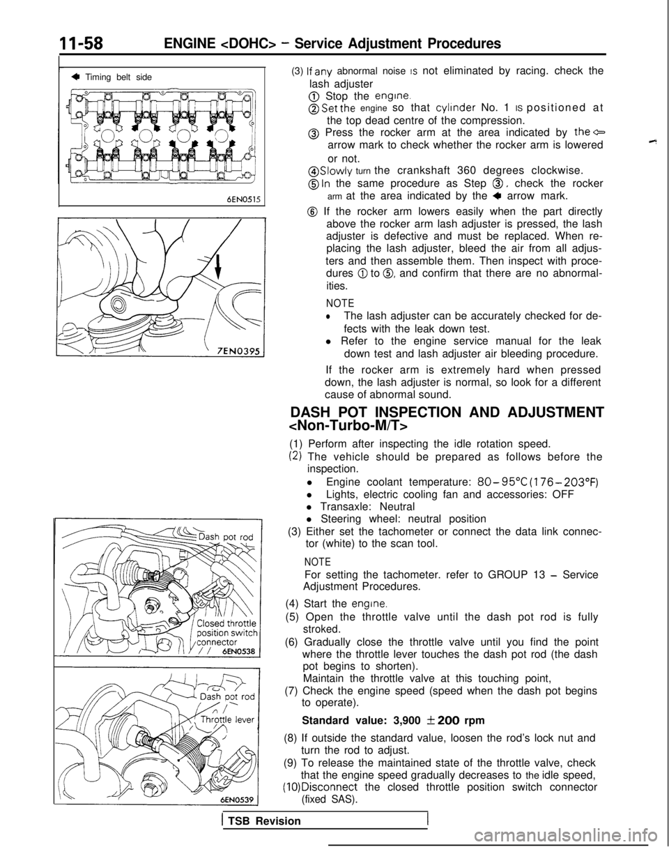
11-58ENGINE
4 Timing belt sideI
6EN0515
(3) lf
any abnormal noise IS not eliminated by racing. check the
lash adjuster
@ Stop the engine.
@ Set the engine so that cylinder
No. 1 IS positioned at
the top dead centre of the compression.
@ Press the rocker arm at the area indicated by the+
arrow mark to check whether the rocker arm is lowered
or not.
@ Slowly turn the crankshaft 360 degrees clockwise.
@ ln the same procedure as Step 0, check the rocker
arm at the area indicated by the
4 arrow mark.
@ If the rocker arm lowers easily when the part directly above the rocker arm lash adjuster is pressed, the lash
adjuster is defective and must be replaced. When re- placing the lash adjuster, bleed the air from all adjus-
ters and then assemble them. Then inspect with proce- dures
@I to 0, and confirm that there are no abnormal-
ities.
NOTE
lThe lash adjuster can be accurately checked for de-
fects with the leak down test.
l Refer to the engine service manual for the leak
down test and lash adjuster air bleeding procedure.
If the rocker arm is extremely hard when pressed
down, the lash adjuster is normal, so look for a different
cause of abnormal sound.
DASH POT INSPECTION AND ADJUSTMENT
(1) Perform after inspecting the idle rotation speed.
(2) The vehicle should be prepared as follows before the inspection.
l Engine coolant temperature:
80- 95°C
(176- 203°F)
lLights, electric cooling fan and accessories: OFF
l Transaxle: Neutral
l Steering wheel: neutral position
(3) Either set the tachometer or connect the data link connec- tor (white) to the scan tool.
NOTE
For setting the tachometer. refer to GROUP 13 - Service
Adjustment Procedures.
(4) Start the
engine.
(5) Open the throttle valve until the dash pot rod is fully
stroked.
(6) Gradually close the throttle valve until you find the point where the throttle lever touches the dash pot rod (the dashpot begins to shorten).
Maintain the throttle valve at this touching point,
(7) Check the engine speed (speed when the dash pot begins to operate).
Standard value: 3,900
f 200 rpm
(8) If outside the standard value, loosen the rod’s lock nut and turn the rod to adjust.
(9) To release the maintained state of the throttle valve, check that the engine speed gradually decreases to the idle speed, (10)Disconnect
the closed throttle position switch connector
(fixed SAS).
1 TSB Revision
Page 109 of 1273
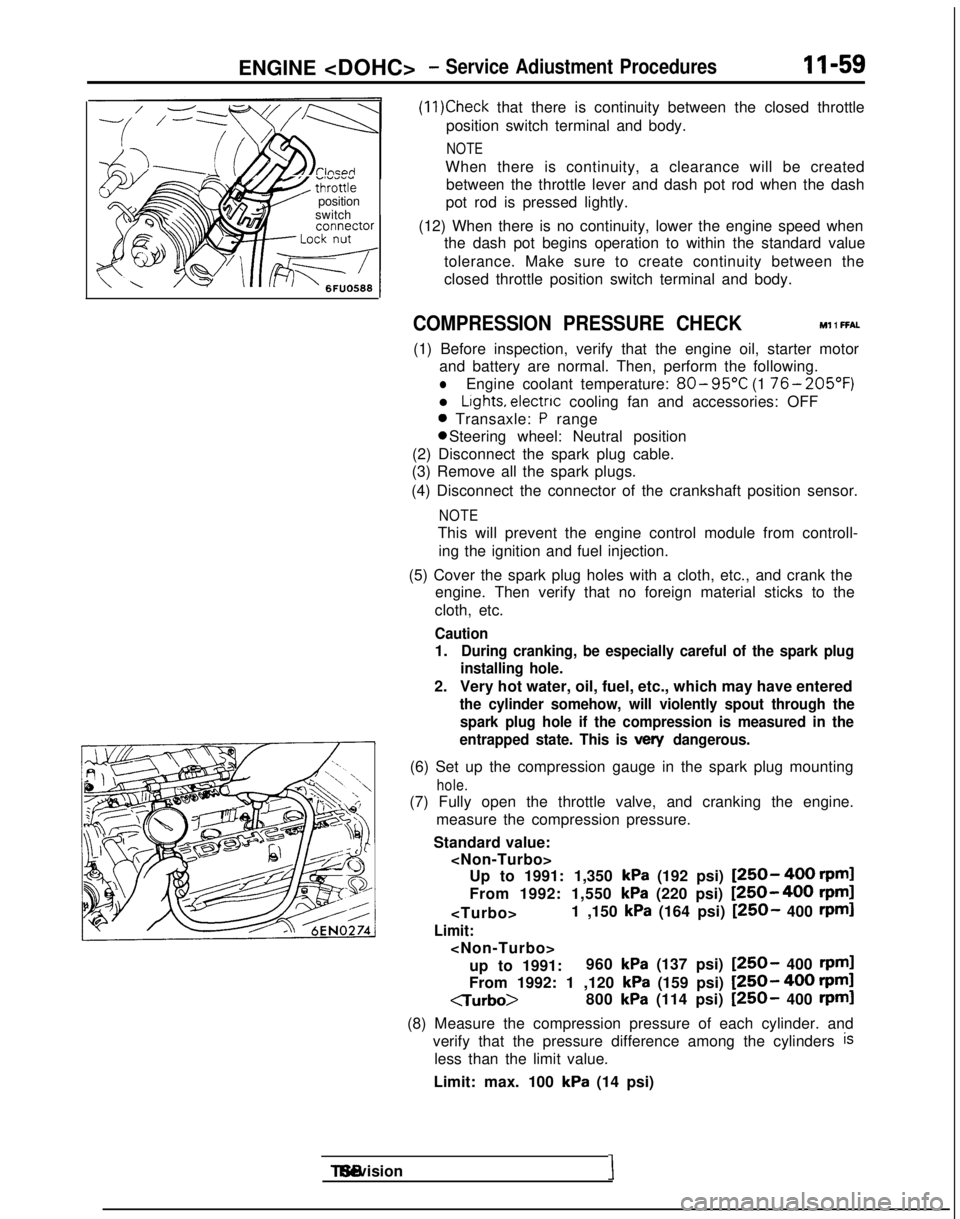
ENGINE
7 Go;;ikv position
switch
(11)Check that there is continuity between the closed throttle
position switch terminal and body.
NOTE
When there is continuity, a clearance will be created between the throttle lever and dash pot rod when the dash
pot rod is pressed lightly.
(12) When there is no continuity, lower the engine speed when the dash pot begins operation to within the standard value
tolerance. Make sure to create continuity between the
closed throttle position switch terminal and body.
COMPRESSION PRESSURE CHECK Ml 1 FFAL
(1) Before inspection, verify that the engine oil, starter motor
and battery are normal. Then, perform the following.
lEngine coolant temperature: 80- 95°C
(1 76- 205’F)
l Lights, electnc
cooling fan and accessories: OFF
0 Transaxle: P range 0 Steering wheel: Neutral position
(2) Disconnect the spark plug cable.
(3) Remove all the spark plugs.
(4) Disconnect the connector of the crankshaft position sensor.
NOTE
This will prevent the engine control module from controll- ing the ignition and fuel injection.
(5) Cover the spark plug holes with a cloth, etc., and crank the engine. Then verify that no foreign material sticks to the
cloth, etc.
Caution
1.During cranking, be especially careful of the spark plug
installing hole.
2. Very hot water, oil, fuel, etc., which may have entered
the cylinder somehow, will violently spout through the
spark plug hole if the compression is measured in the
entrapped state. This is
vex/ dangerous.
(6) Set up the compression gauge in the spark plug mounting
hole.
(7) Fully open the throttle valve, and cranking the engine.
measure the compression pressure.
Standard value:
kPa (192 psi) [250- 400 rpml
From 1992: 1,550
kPa (220 psi) [250-400 rpm]
Limit:
up to 1991: 960
kPa (137 psi) [250- 400 rpml
From 1992: 1 ,120 kPa (159 psi) [250- 400 rpml
CTurbo>
800
kPa (114 psi) [250- 400 rpml
(8) Measure the compression pressure of each cylinder. and verify that the pressure difference among the cylinders
is
less than the limit value.
Limit: max. 100
kPa (14 psi) TSB Revision
I