1988 PONTIAC FIERO key
[x] Cancel search: keyPage 562 of 1825
DRIVEABILITY AND EMISSIONS 5.OL (VIN E) 6EZ-C1-7
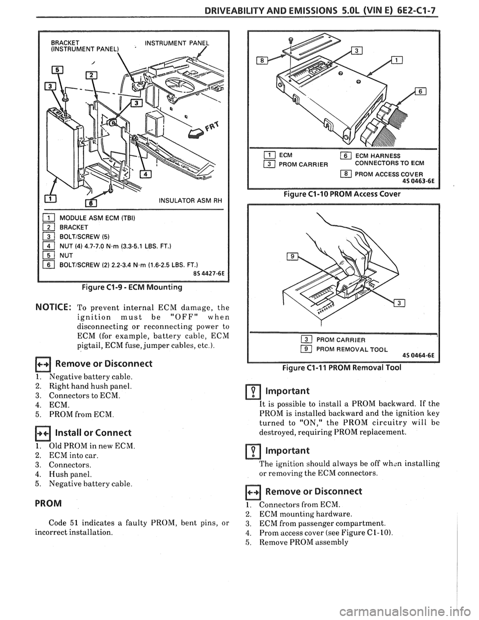
BRACKET
INSTRUMENT PANEL
(INSTRUMENT PANEL) '
MODULE ASM ECM (TBI)
BRACKET
1 BOLTISCREW (5) - 1 NUT (4) 4.7-7.0 N.rn (3.3-5.1 LBS. FT.)
NUT
BOLTISCREW (2) 2.2-3.4 N,rn (1.6-2.5 LBS. FT.)
Figure C1-9 - ECM Mounting
NOTICE: To prevent internal ECM damage, the
ignition must be
"OFF" when
disconnecting or reconnecting power to
ECM (for example, battery cable, ECM
pigtail, ECM fuse, jumper cables,
etc.).
Remove or Disconnect
1. Negative battery cable.
2. Right hand hush panel.
3. Connectors to ECM.
4. ECM.
5. PROM from ECM.
Install or Connect
1. OldPROMinnewECM.
2. ECM into car.
3. Connectors.
4. Hush panel.
5. Negative battery cable.
PROM
Code 51 indicates a faulty PROM, bent pins, or
incorrect installation.
ECM HARNESS
PROM CARRIER CONNECTORS TO ECM
1 PROM ACCESS COVER 45 0463-6E
Figure C1-10 PROM Access Cover
1 PROM REMOVAL TOOL 45 0464-6E
Figure C1-I 1 PROM Removal Tool
Important
It is possible to install a PROM backward. If the
PROM is installed backward and the ignition key
turned to "ON," the PROM circuitry will bc
destroyed, requiring PROM replacement.
lmportant
The ignition should always be off wh~n installing
or removing the ECM connectors.
Remove or Disconnect
1. Connectors from ECM.
2. ECM mounting hardware.
3. ECM from passenger compartment.
4. Prom access cover (see Figure C 1- 10)
5, Remove PROM assembly
Page 576 of 1825
DRIVEABILIW AND EMISSIONS - 5.OL (VIN E) 6E2-62-1
SECTION C2
FUEL CONTROL SYSTEM
TBI MODEL 228
CONTENTS
GENERAL DESCRIPTION . . . . . . . . . . . . . . . C2-1
PURPOSE ......................... C2-1
MODES OF OPERATION . . . . . . . . . . . . . . C2-1
Starting Mode . . . . . . . . . . . . . . . . . . . C2-1
Clear Flood Mode . . . . . . . . . . . . . . . . C2-2
RunMode . . . . . . . . . . . . . . . . . . . . . . C2-2
Open Loop . . . . . . . . . . . . . . . . . . . . . . C2-2
Closed Loop . . . . . . . . . . . . . . . . . . . . . C2-2
Acceleration Mode . . . . . . . . . . . . . . . C2-2
Deceleration Mode . . . . . . . . . . . . . . . C2-2
Battery Correction Mode . . . . . . . . . . . C2-2
Fuel Cut Off Mode . . . . . . . . . . . . . . . . C2-2
FUEL CONTROL SYSTEM COMPONENTS
. . . C2-2
BASIC SYSTEM OPERATION . . . . . . . . . . . C2-3
THROTTLE BODY INJECTION (TBI) UNIT. . . C2-3
Fuel Injectors . . . . . . . . . . . . . . . . . . . . C2-3
Pressure Regulator . . . . . . . . . . . . . . . C2-3
ldle Air Control (IAC) Valve . . . . . . . . . . C2-4
Throttle Position Sensor (TPS) . . . . . . . . C2-4
FUEL PUMP.. . . . . . . . . . . . . . . . . . . . . . . C2-5
FUEL PUMP ELECTRICAL CIRCUIT . . . . . . . C2-5
DIAGNOSIS . . . . . . . . . . . . . . . . . . . . . . * C2-5
FUEL CONTROL . . . . . . . . . . . . . . . . . . . . C2-5
GENERAL DESCRIPTION
PURPOSE
The basic function of the fuel control system is to
control fuel delivery to the engine. Fuel is delivered to
the engine by
a throttle body injection ('FBI) unit.
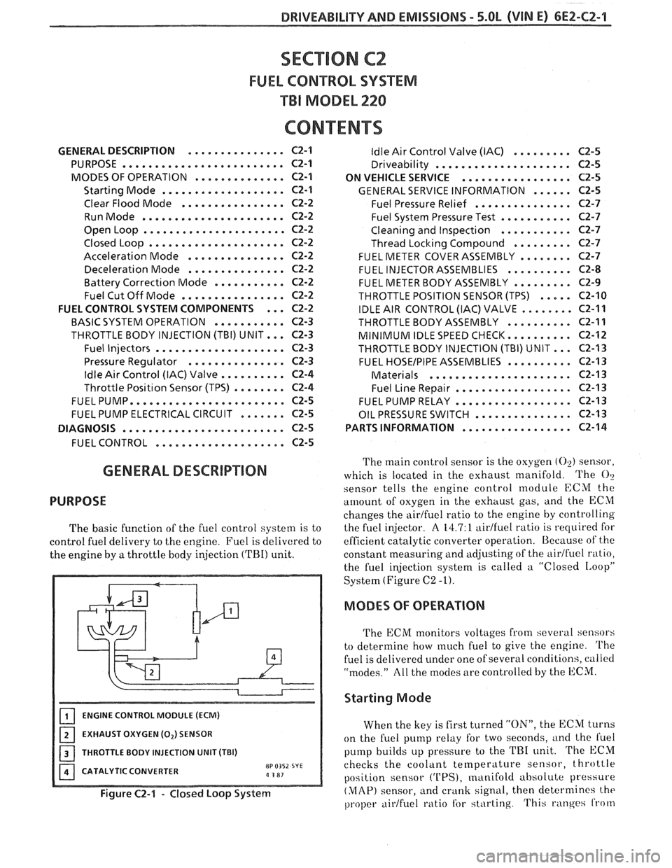
ENGINE CONTROL MODULE (ECM)
EXHAUST OXYGEN (0,) SENSOR
I 1 THROTTLE BODY INJECTION UNIT (TBI)
CATALYTIC CONVERTER
8P 0352 SYE a 3 81
Figure C2-1 - Closed Loop System
ldle Air Control Valve (IAC) . . . . . . . . . C2-5
Driveability . . . . . . . . . . . . . . . . . . . .. C2-5
ON VEHICLE SERVICE
. . . . . . . . . . . . . . . . . C2-5
GENERAL SERVICE INFORMATION . . . . . . C2-5
Fuel Pressure Relief . . . . . . . . . . . . . . . C2-7
Fuel System Pressure Test . . . . . . . . . . . C2-7
Cleaning and Inspection . . . . . . . . . . . C2-7
Thread Locking Compound . . . . . . . . . C2-7
FUEL METER COVER ASSEMBLY . . . . . . . . C2-7
FUEL INJECTOR ASSEMBLIES . . . . . . . . . . C2-8
FUEL METER BODY ASSEMBLY . . . . . . . . . C2-9
THROTTLE POSITION SENSOR (TPS) . . . . . C2-10
IDLE AIR CONTROL (IAC) VALVE . . . . . . . . C2-11
THROTTLEBODYASSEMBLY .......... C2-11
MINIMUM IDLE SPEED CHECK.. . . . . . . . . C2-12
THROTTLE BODY INJECTION (TBI) UNIT.. . C2-I3
FUEL HOSEIPIPE ASSEMBLIES . . . . . . . . . . C2-13
Materials . . . . . . . . . . . . . . . . . . . . . . C2-13
Fuel Line Repair . . . . . . . . . . . . . . . . . . C2-13
FUEL PUMP RELAY . . . . . . . . . . . . . . . . . . C2-13
OIL PRESSURE SWITCH . . . . . . . . . . . . . . . C2-13
PARTS INFORMATION
. . . . . . . . . . . . . . . . . C2-14
The main control sensor is the oxygen (02) sensor,
which is located in the exhaust manifold. The
O?
sensor tells
the engine control module ECM the
amount of osygen in the exhttust gas, and the ECM
changes the airtfuel ratio to the engine by controlling
the fuel injector.
A 14.7: 1 aidfuel ratio is required for
efficient catalytic converter operation. Because of the
constant measuring and adjusting of the
airlfuel ratio,
the fuel injection system is called a "Closed
IAoopP
System (Figure C2 -1).
MODES OF OPERATION
The ECM monitors voltages from several sensors
to determine how
much fuel to give the engine. The
fuel is delivered under one of several conditions, called
"modes." All the modes are controlled by the ECM.
Starting Mode
When the key is first turned "ON", the ECM turns
on the fuel pump relay for two seconds,
i~nd the l'uel
pump builds up pressure to the TRI unit. The ECM
checks the coolant
temperature sensor, throttle
position sensor
('UPS), manifold absolute pressure
(MAP) sensor, and crank signal, then determines the
proper airtfuel ratio tbr starting. This ranges from
Page 578 of 1825
DRIVEABILITY AND EMlSSlONS - 5.0L (VIN E) 6E2-C2-3
BASIC SYSTEM OPERATION
The fuel control system (Figure C2-2) has an
electric fuel pump, located in the fuel tank with the
gage sending unit, which pumps fuel to the TBI
through the fuel supply line, then through an in-line
fuel filter. The pump is designed to provide
pressurized fuel at about 125
kPa (18 psi). A pressure
regulator in the TBI keeps fuel available to the
injectors at a constant pressure between 62 and 90
kPa (9 and 13 psi). Fuel in excess of injector need is
returned to the fuel tank by
a separate line.
The ECM controls the injectors that are located in
the fuel meter body assembly of the TBI. The injectors
deliver fuel in one of several modes, described above.
In order to properly control the fuel supply, the
fuel pump is operated by the ECM through the fuel
pump relay and oil pressure switch (see "Fuel Pump
Electrical Circuit").
THROTTLE BODY INJECTION (TBI) UNIT
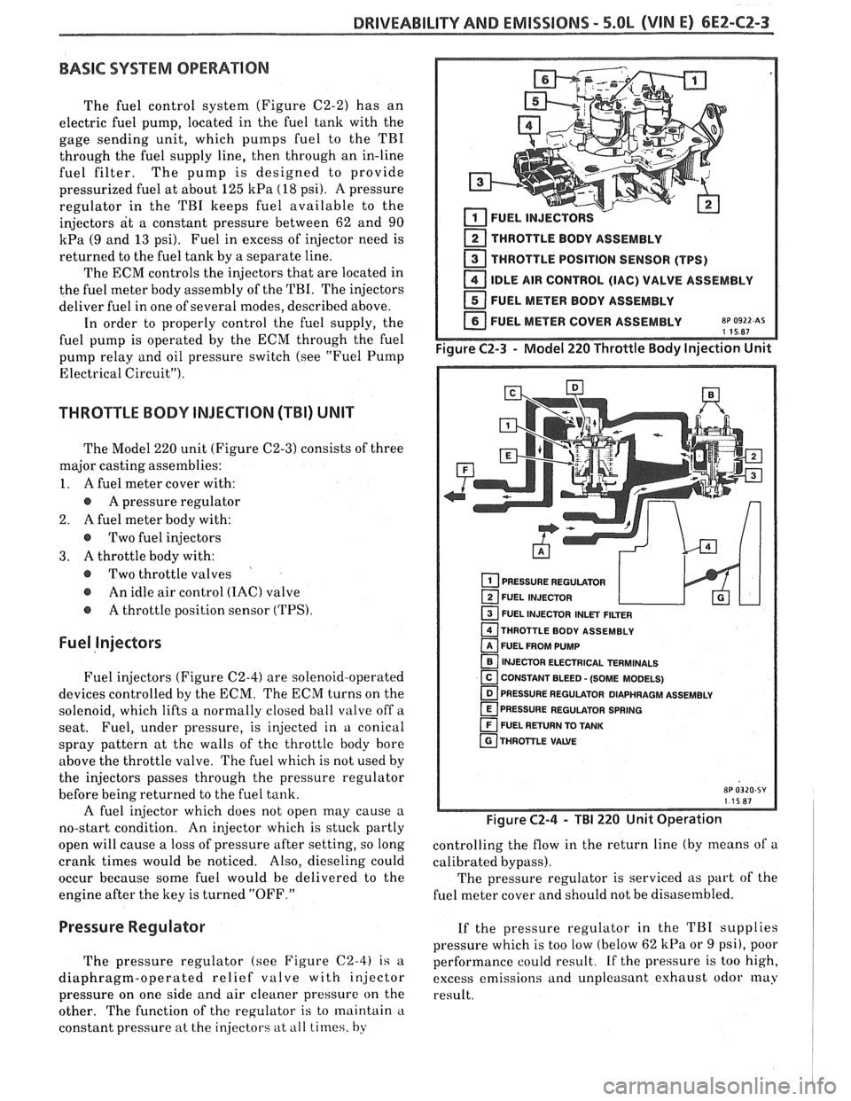
The Model 220 unit (Figure C2-3) consists of three
major casting assemblies:
1. A fuel meter cover with:
A pressure regulator
2.
A fuel meter body with:
@ Two fuel injectors
3. A throttle body with:
@ Two throttle valves
@ An idle air control (IAC) valve
@ A throttle position sensor (TPS).
Fuel Injectors
Fuel injectors (Figure C2-4) are solenoid-operated
devices controlled by the ECM. The ECM turns on the
solenoid, which lifts a normally closed ball valve off a
seat. Fuel, under pressure, is injected in a conical
spray pattern at the walls of
the throttle body bore
above the throttle valve. The fuel which is not used by
the injectors passes through the pressure regulator
before being returned to the fuel tank.
A fuel injector which does not open may cause a
no-start condition. An injector which is stuck partly
open will cause a loss of pressure after setting, so long
crank times would be noticed. Also, dieseling could
occur because some fuel would be delivered to the
engine after the key is turned "OFF."
2 THROTTLE BODY ASSEMBLY
THROTTLE POSITION SENSOR (TPS)
IDLE AIR CONTROL (IAC) VALVE ASSEMBLY
FUEL METER BODY ASSEMBLY
FUEL METER COVER ASSEMBLY
8~ 0922 AS 115R7
PRESSURE REGULATOR
FUEL INJECTOR
1 FUEL INJECTOR INLET FILTER
THROTTLE BODY ASSEMBLY
FUEL FROM PUMP
INJECTOR ELECTRICAL TERMINALS
[ CONSTANT BLEED - (SOME MODELS) - PRESSURE REGULATOR DIAPHRAGM ASSEMBLY
PRESSURE REGULATOR SPRING
FUEL RETURN TO TANK
THROTTLE
VAWE
Figure C2-4 - TBI 220 Unit Operation
controlling the flow in the return line (by means of a
calibrated bypass).
The pressure regulator is serviced as part
of the
fuel meter cover and should not be disasembled.
Pressure Regulator If the pressure regulator in the TBI supplies
pressure which
is too low (below 62 kPa or 9 psi), poor
The pressure regulator (see Figure
C2-4) is a performance could result. if the pressure is too high,
diaphragm-operated relief valve with injector excess emissions and unpleasant exhaust odor
may
pressure on one side and air cleaner pressure on the
result.
other. The function of the regulator is to maintain
'1
constant pressure at the in.jecto1.s at ill1 times, by
Page 580 of 1825

DRIVEABILITY AND EMISSIONS - 5.OL (\/IN El 6EZ-CZ-5
sent to the ECM. The ECM then increases the injector
base pulse width, permitting increased fuel flow.
As the throttle valve rotates in response to
movement of the accelerator pedal, the throttle shaft
transfers this rotational movement to the
'I'PS. A
potentiometer (variable resistor) within the TPS
assembly changes its resistance (and voltage drop) in
proportion to throttle movement.
By applying a reference voltage (5.0 volts) to the
TPS input, a varying voltage (reflecting throttle
position) is available at the TPS output. For example,
approximately 2.5 volts results from a 50% throttle
valve opening (depending on TPS calibration). The
voltage output from the TPS assembly is routed to the
ECM for use in determining throttle position.
FUEL PUMP
The fuel pump is a turbine type, low pressure
electric pump, mounted in the fuel tank. Fuel
is
pumped at a positive pressure (above 62
kPa or 9 psi)
from the fuel pump through the in-line filter to the
pressure regulator in the TBI assembly Excess
fuel is
returned to the fuel tank through the fuel return line.
The fuel pump is attached to the fuel gage sender
assembly. A fuel strainer is attached to the fuel pump
inlet line and prevents dirt particles from entering the
fuel line and tends to separate
water from the fuel
Vapor lock problems are reduced when using an
electric
pump because the fuel is pushed from the tank
under pressure rather than being pulled
under
vacuum, a condition that produces vapor.
An inoperative fuel pump would cause
a. no start
condition. A fuel pump which does not provide enough
pressure can result in poor performance. (See "Fuel
System Pressure Test" procedure).
FUEL PUMP ELECTRICAL CIRCUIT
When the key is first turned "ON" without the
engine running, the ECM turns the
Fuel pump relay
"ON" for two seconds. This builds
up the fuel pressure
quickly. If the engine is not started within two
seconds, the
ECM shuts the fuel pump "OFF" and
waits until the engine starts. As soon as the engine is
cranked, the ECM turns the relay
"ON" and runs the
fuel pump.
As a backup system to the fuel pump relay, the
fuel pump can also be turned on
by the oil pressure
switch. The oil pressure sender has two circuits
internally. One operates the oil pressure indicator or
gage in the instrument cluster,
itnd the other is
anormally open switch which closes when oil pressure
reaches about 28
kPa (4 psi). If the fuel pump relay
fails, the oil pressure switch will run the fuel pump. An
inoperative fuel pump relay can result in long
cranking times, particularly if the engine is cold. The
oil pressure switch will turn on the fuel pump as soon
as oil pressure
reaches about 28 kPa (4 psi).
FUEL CONTROL
Always start with the "Diagnostic Circuit Check"
in Section
"6E2-A". This will reduce diagnosis time
and prevents unnecessary replacement of parts. The
information in this check will direct diagnosis
concerning "Engine
Crunlis But Won't Run" and the
"Fuel Control System," Section
"6E2-C2", including
diagnosis of an injector, pressure regulator,
fuel pump,
fuel
pump relay, and oil pressure switch.
Idle Air Control (IAC) Valve
A "Scan" tool reads IAC position in steps, calletl
"Counts." "0" steps indicates the ECM is commanding
the
IAC to be driven in, to a fully seiltetl position
(minimum idle air).
The higher the number steps, the
more idle air being allowed to pass
by the IAC valve.
cnose Refer to CHART C-2C for information to cliil,
the function of the IAC valve.
Driva bility
Refer to Section "B" for driveability symptoms
related to the fuel control.
ON-VEHICLE SERVICE
GENERAL SEWVICE INFORMATION
CAUTION:
e To prevent personal injury or damage to the
vehicle
as the result sf an accidental start,
disconnect and reconnect the negative
battery cable before and after service is
performed.
@ Also, catch any fuel that leaks out when
disconnecting the fuel lines, by covering the
fittings with
a shop cloth. Place the cloth in
an approved container when work is
complete.
The 'FBI unit repair procedures cover component
replacement with the unit on the vehicle,
tIowever,
throttle body replacement requires that the complete
unit
be removed from the enginc.
Page 601 of 1825
6E2-C4-2 5.8L (VIN E) DRIVEABILIW AND EMISSIONS
Therefore, detonation could be caused by low MAP
output or high resistance in the coolant sensor circuit.
Poor performance could be caused by high MAP
o~~tput or low resistance in the coolant sensor circuit.
HOW CODE 42 IS DETERMINED
When the system is running on the HE1 module,
that is, no voltage on the bypass line, the
HE1 module
grounds the EST signal. The ECM expects to see no
voltage on the EST line during this condition. If it
sees a voltage, it sets Code
42 and will not go into the
EST mode. When the rpm for EST is reached (about
400 rpm),
the ECM applies 5 volts to the bypass line and the EST
should no longer be grounded in the
HE1 module, so,
the EST voltage should be varying.
If the bypass line is open, the
HE1 module will not
switch to EST mode, so, the EST voltage will be low
and Code
42 will be set.
If the EST line is grounded, the HE1 module will
switch to EST but, because the line is grounded, there
will be no EST signal and the engine will not run. A
Code
42 may, or may not, be set.
The description, operation, and diagnosis of the
HE1 system are found in Section 6D of this manual.
This section will address diagnosis of that portion of
the Ignition System pertaining to the EST operation.
CODE 12
Code 12 is used during the Diagnostic Circuit
Check procedure to test the code display ability of the
ECM. This code indicates that the ECM is not
receiving the engine rpm (REFERENCE) signal. This
occurs with the ignition key
"ON" and the engine not
running.
The "Reference" signal, also, triggers the fuel
injection system. Without the "Reference" signal, the
engine cannot run.
ON-CAR SERVICE
SETTING TIMING
Set timing according to instructions on Vehicle
Emission Control Information label.
PARTS INFORMATION
PART NAME GROUP
....................... Module, Distr 2.383
......................... Coil, Distr 2.170
Page 653 of 1825
6E3-8 2.8L (VIM $1, 5.OL (VIN F) & 5.7L(VlN 8) BRlVEABILlTY AND EMISSIOMS
ALL NEW GENERAL MOTORS VEHICLES ARE CERTIFIED BY THE UNITED STAEES
ENVIRONMENTAL PROTECTION AGENCY AS CONFOWMlNG TO "THE REQUIREMENTS QF THE
REGULATIONS FOR THE CONTROL OF AIR POLLUTION FROM NEW MOTOR VEHICLES. THIS
CERTlFlCATlON IS CONTINGENT ON CERTAIN ADJUSTMENTS BEING SET TO FACTORY
STANDARDS. IN MOST CASES, THESE ADJUSTMENT POINTS EITHER HAVE BEEN
PERMANENTLY SEALED ANDIOR MADE
INACCESSlBLE TO PREVENT INDISCRIMINATE OR
ROUTINE ADJUSTM&M"FIN THE FIELD. FOR THIS REASON, THE FACTORY PROCEDURE FOR
TEMPORARILY REMOVING PLUGS, CAPS, ETC., FOR PURPOSES OF SERVICING THE PRODUCT,
MUST
BE STRICTLY FOLLOWED AND, WHEREVER PRACTICABLE, RETURNED TO THE
ORIGINAL INTENT QF THE DESIGN.
INTRODUCTION
GENERAL BESCRIPT18N DIAGNOSIS PROCEDURE
This section applies to engines which have a fuel
injector in the intake manifold near the intake valve
for each cylinder. It is commonly referred to as "Port
Fuel Injection".
These engines have controls to reduce exhaust
emissions, while maintaining good driveability and
fuel economy.
An engine control module
(ECM) is the heart of
this control system and has sensors used to provide
information about engine operation and the various
systems it controls. Details of basic operation,
diagnosis, functional checks, and on-vehicle service
are covered in Section "C", "Component Systems".
The ECM has the ability to do some diagnosis of
itself, and of other parts of the system. When it finds a
problem, it lights a "Service Engine Soon" light on the
instrument panel and
a trouble code will be stored in
the ECM memory. This does not mean that the engine
should be stopped right away, but that the cause of the
light coming
"ON" should be checked as soon as
reasonably possible. The
following
sections(s) are written for specific
engine applications and are clearly indentified. Be
sure to use only the section which applies to the
engine family being diagnosed.
Before using this section of the manual, you
should be familiar with the information and the
proper diagnosing procedures as described in Section
"GE". If the proper diagnosis procedures are not
followed, as described in Section
"6EM, it may result in
unnecessary replacement of good parts.
Trouble tree charts incorporate diagnosis
procedures using an ALDL "SCAN" tool where
possible.
The "SCANJ' tool has the ability to save time
in diagnosis and prevent the replacement of good
parts. The
key to using the "SCAN" tool
successfully for diagnosis lies in the technician's
ability to understand the system he is
trving to
diagnose. as well as an understanding of the
"SCAN" tool's limitations. See Section "6E" for
more information.
Page 671 of 1825
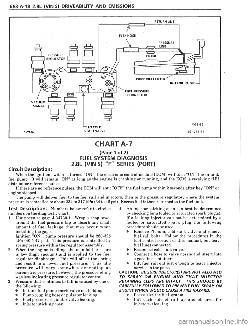
6E3-A-I8 2.8b (VIN 5) DRIVEABILITY AND EMISSIONS
PUMP INLET FILTER
IN-TANK PUMP
FUEL
PRESSURE CONNECTOR
CHART A-7
(Page 4 of 2)
FUEL SYSTEM DsAGNOSBS
2.8L (VIN S) ""FYSERBES (PORT)
Circuit Description:
When the ignition switch is turned "ON", the electronic control module (ECM) will turn "ON" the in-tank
fuel pump. It will remain "ON" as long as the engine is cranking or running, and the ECM is receiving
HE1
distributor reference pulses.
If there are no reference pulses, the ECM will shut "OFF" the fuel pump within
2 seconds after key "ON" or
engine stopped.
The pump will deliver fuel to the fuel rail and injectors, then to the pressure regulator, where the system
pressure is controlled to about 234 to 317
kPa (34 to 46 psi). Excess fuel is then returned to the fuel tank.
Test Description: Numbers below refer to circled
numbers on the diagnostic chart.
1. Use pressure gage 5-34730-1. Wrap a shop towel
around the fuel pressure tap to absorb any small
amount of fuel leakage that
may occur when
installing the gage.
Ignition "ON", pump pressure should be 280-325
kPa (40.5-47 psi). This pressure is controlled by
spring pressure within the regulator assembly.
2. When the engine is idling, the manifold pressure
is low (high vacuum) and is applied to the fuel
regulator diaphragm. This will offset the spring
and result in a lower fuel pressure.
'This idle
pressure will vary somewhat depending on
barometric pressure, however, the pressure idling
was less indicating pressure regulator control.
3. Pressure that continues to fall is caused by one of
the following:
In-tank fuel pump check valve not holding.
@ Pump coupling hose or pulsator leaking.
Fuel pressure regulator valve leaking.
@ Injector sticking open. 4.
An injector sticking open can best be determined
by checking for a fouled or saturated spark
plug(s).
If a leaking injector can not be determined by a
fouled or saturated spark plug the following
procedure should be used.
e Remove Plenum, cold start valve and remove
fuel rail bolts. Follow the procedures in the
fuel control section of this manual, but leave
fuel lines connected.
@ Reconnect cold start valve.
@ Connect a hose to valve nozzle and insert into
a gasoline container.
@ Lift fuel rail out just enough to leave injector
nozzles in the ports.
CAUTION: BE SURE INJEePOR(S) ARE NOT ALLOWED
PO SPRAY ON ENGINE AND THAT INJECTOR
RETAINING
CLIPS ARE INTACT. PHIS SHOULD BE
CAREFULLY
FOLLOWD PO PREVENT FUEL SPRAY ON'
ElZIGlNE WHICH WOULD CAUSE A FIRE HAZARD.
@ Pressurize the fuel system.
@ I.if't each side of rail up and observe for
injc~ctot-l.) It.ulting
Page 715 of 1825
6E3-B-6 2.8L (VIN 5) DRIVEABILITY AND EMISSIONS
POOR FUEL ECONOMY
Definition: Fuel economy, as measured by an actual road test, is
noticeably lower than expected. Also, economy is noticeably lower than
it was on this car at one time, as previously shown by an actual road test.
@ Perform careful visual check as described at
start of Section "B".
8 CHECK:
- Coolant level.
- Engine thermostat for faulty part (always
open) or for wrong heat range. See Section
"6B".
- Compression
- Ignition timing. See Emission Control
Information label.
- TCC for proper operation. A "ScanJ' should
indicate an rpm drop when the TCC is
commanded "ON". See CHART C-8.
- Induction system and crankcase for air leaks.
8 Check for exhaust restriction.
See CHART
B-1.
DIESELING, RUN-ON
Definition: Engine continues to run after key is
turned "OFF", but runs very roughly. If engine runs
smoothly, check ignition switch and adjustment.
8 Check injectors for leaking. See CHART A-7.
ROUGH, UNSTABLE, OR INCORRECT IDLE, STALLING
Definition: The engine runs unevenly at idle. If bad enough, the car may
shake. Also, the idle may vary in rpm (called "hunting"). Either
condition
may be bad enough to cause stalling. Engine idles at incorrect speed.
@ Perform careful visual check as described at
start of Section "B".
@ CHECK:
- Throttle linkage for sticking or binding. Also
check TPS adjustment. Refer to Section
"C2".
- Ignition timing. See Emission Control
Information label.
- ECM ground circuits.
- IAC system. See CHART C-2C.
- Generator output voltage. Repair if less than 9
or more than 16 volts.
- PIN switch circuit. See CHART C-lA, or use
"SCAN" tool.
- Injector balance. See CHART C-'LA.
- PCV valve for proper operation by placing
finger over inlet hole in valve end several times.
Valve should snap back. If not, replace valve.
- Evaporative Emission Control System. CHART
C-3.
- A/C signal to ECM terminal "B8" (5.OL & 5.7L).
"Scan" tool should indicate AIC is being
requested when ever
A/C is selected and the
pressure cycling switch is closed.
- A/C system operation (2.8L) - See CHAR'l' (2-10.
- Minimum idle speed. See Section "C2".
- Loose or damaged MAF sensor duct between
sensor and throttle body.
- Power Steering Pressure Switch (2.81, - See
CHART
C-1E.
Check AIR system. There should be no AIR to
ports while in "Closed Loop". See CHART C-6.
EGR valve: There should be no EGR at idle.
Run a cylinder compression check. See Section
"6". Inspect oxygen sensor for silicon contamination
from fuel, or use of improper RTV sealant. The
sensor will have a white, powdery coating, and
will result in a high but false signal voltage (rich
exhaust indication). The ECM will then reduce
the
amount of fuel delivered to the engine,
causing a severe driveability problem.
Check for fuel in pressure regulator hose. If
present replace regulator assembly.
Check ignition system; wires, plugs, rotor, etc.
Check for loose or damaged air duct between
MAF sensor and throttle body.
Ilisconnect MAF sensor and if condition is
corrected replace sensor.
Clean injectors.
Monitoring block learn will help identify the
cause of the problem. If the system is runnig lean
(block learn greater than
138), refer to
"Diagnostic Aids" on facing page of Code
44. If
the system is running rich (block learn less than
118), refer to "Diagnostic Aids'' on facing page of
Code 45.