1988 PONTIAC FIERO key
[x] Cancel search: keyPage 1147 of 1825
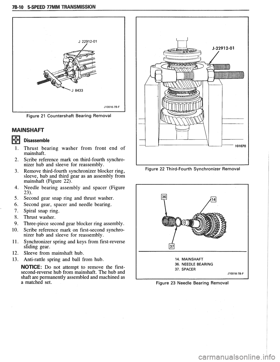
Figure 21 Countershaft Bearing Removal
Disassemble
I. Thrust bearing washer from front end of
mainshaft.
2. Scribe reference
mark on third-fourth synchro-
nizer hub and sleeve for reassembly.
3. Remove third-fourth synchronizer blocker ring, Figure 22 Third-Fourth Synchronizer Removal
sleeve, hub and third gear as an assembly from
mainshaft (Figure
22).
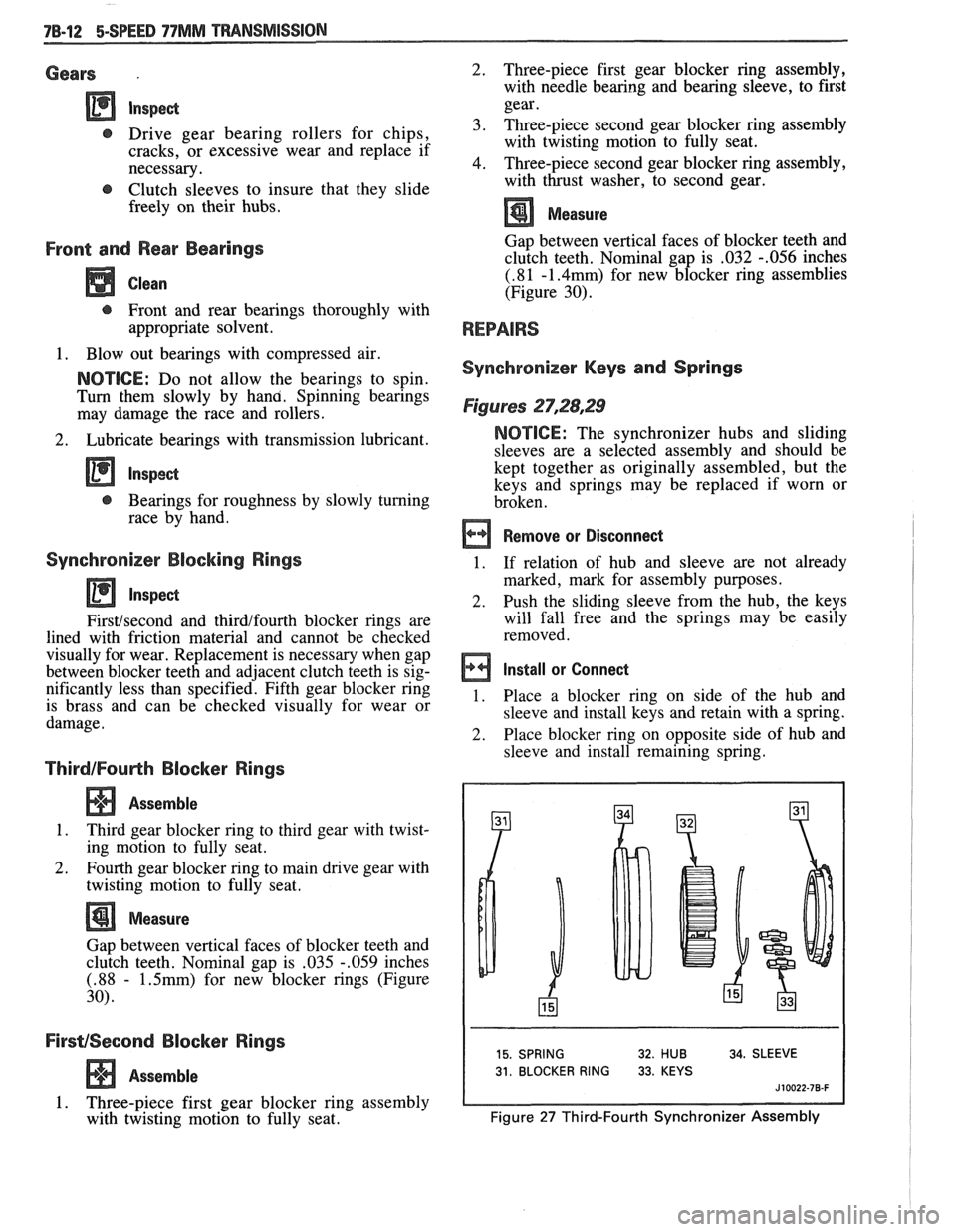
4. Needle bearing assembly and spacer (Figure
23).
5. Second gear snap ring and thrust washer.
6. Second gear, spacer and needle bearing.
7. Spiral snap ring.
8. Thrust washer.
9. Three-piece second gear blocker ring assembly.
10. Scribe reference mark on first-second synchro-
nizer hub and sleeve for reassembly.
1 I. Synchronizer spring and keys from first-reverse
sliding gear.
12. Sleeve from mainshaft hub.
13. Anti-rattle spring and ball from hub.
NOTICE: Do not attempt to remove the first-
second-reverse hub from mainshaft. The hub and
shaft are permanently assembled and machined as
a matched set.
14. MAINSHAFT
36. NEEDLE BEARING
37. SPACER
Figure 23 Needle Bearing Removal
Page 1149 of 1825
Gears .
t, Drive gear bearing rollers for chips,
cracks, or excessive wear and replace if
necessary.
@ Clutch sleeves to insure that they slide
freely on their hubs.
Front and Rear Bearings
Clean
t, Front and rear bearings thoroughly with
appropriate solvent.
1. Blow out bearings with compressed air.
NOTICE: Do not allow the bearings to spin.
Turn them slowly by hana. Spinning bearings
may damage the race and rollers.
2. Lubricate bearings with transmission lubricant.
@ Bearings for roughness by slowly turning
race by hand.
Synchronizer Blocking Rings
Firsthecond and thirdlfourth blocker rings are
lined with friction material and cannot be checked
visually for wear. Replacement is necessary when gap
between blocker teeth and adjacent clutch teeth is sig-
nificantly less than specified. Fifth gear blocker ring
is brass and can be checked visually for wear or
damage.
ThirdIFouHh Blocker Rings
Assemble
1. Third gear blocker ring to third gear with twist-
ing motion to fully seat.
2. Fourth gear blocker ring to main drive gear with
twisting motion to fully seat.
Measure
Gap between vertical faces of blocker teeth and
clutch teeth. Nominal gap is
.035 -.059 inches
(.88 - 1.5mm) for new blocker rings (Figure
30).
FirsvSecond Blocker Rings
Assemble
1. Three-piece first gear blocker ring assembly
with twisting motion to fully seat. 2.
Three-piece first gear
blocker ring assembly,
with needle bearing and bearing sleeve, to first
gear.
3. Three-piece second gear blocker ring assembly with twisting motion to fully seat.
4. Three-piece second gear blocker ring assembly,
with thrust washer, to second gear.
Measure
Gap between vertical faces of blocker teeth and
clutch teeth. Nominal gap is ,032
-.056 inches
(.81 -1.4mm) for new blocker ring assemblies
(Figure 30).
Synchronizer Keys and Springs
Figures 27,28,29
NOTICE: The synchronizer hubs and sliding
sleeves are a selected assembly and should be
kept together as originally assembled, but the
keys and springs may be replaced if worn or
broken.
Remove or Disconnect
1. If
relation of hub and sleeve are not already
marked, mark for assembly purposes.
2.
Push the sliding sleeve from the hub, the keys
will fall free and the springs may be easily
removed.
Install or Connect
1. Place a blocker ring on side of the hub and
sleeve and install keys and retain with a spring.
2. Place blocker ring on opposite side of hub and
sleeve and install remaining spring.
15. SPRING 32. HUB 34. SLEEVE
31. BLOCKER RING 33. KEYS
J 10022-78-F
Figure 27 Third-Fourth Synchronizer Assembly
Page 1150 of 1825
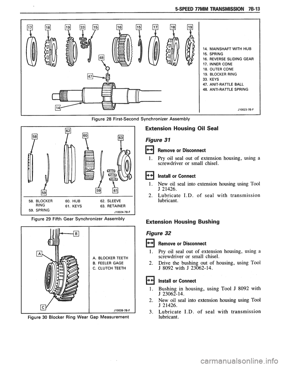
14. MAINSHAFT WITH HUB
15. SPRING
16. REVERSE SLIDING GEAR
17, INNER CONE
18. OUTER CONE
19. BLOCKER RING
33. KEYS
47.
ANIT-RAlTLE BALL
48. ANTI-RATTLE SPRING
Figure 28 First-Second Synchronizer Assembly
63. RETAINER
Figure 29 Fifth Gear Synchronizer Assembly
Extension Housing Oil Seal
Figure 31
Remove or Disconnect
1. Pry oil seal
out of extension housing, using a
screwdriver or small chisel.
Install or Connect
1. New oil seal into extension housing using Tool
J 21426.
2. Lubricate
I.D. of seal with transmission
lubricant.
Extension Housing Bushing
A. BLOCKER TEETH
B. FEELER GAGE
C. CLUTCH TEETH
Figure 32
rn Remove or Disconned
1. Pry oil seal out of extension housing, using a
screwdriver or small chisel.
2. Drive the bushing
out of housing, using Tool
J 8092 with J 23062-14.
Install or Connect
1. Bushing in housing, using Tool J 8092 with
J 23062-14.
2. New
oil seal into extension housing using
Tm1
J 21426.
3. Lubricate
I.D. of seal with transmission
Figure 30 Blocker Ring Wear Gap Measurement lubricant.
Page 1153 of 1825
78-16 BSPEED 77MM TMNSMISSION
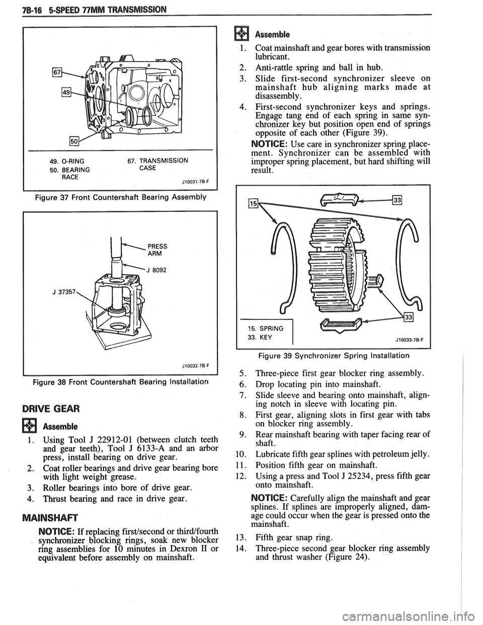
49. O-RING 67. TRANSMISSION
50. BEARING CASE
Figure 37 Front Countershaft Bearing Assembly
Figure
38 Front Countershaft Bearing Installation
DRIVE GEAR
Assemble
1. Using Tool J 22912-01 (between clutch teeth
and gear teeth), Tool
J 6133-A and an arbor
press, install bearing on drive gear.
2. Coat roller bearings and drive gear bearing bore
with light weight grease.
3. Roller bearings into bore of drive gear.
4. Thrust bearing and race in drive gear.
MAINSHAm
NOTICE: If replacing firstfsecond or thirdlfourth
synchronizer blocking rings, soak new blocker
ring assemblies for 10 minutes in Dexron
I1 or
equivalent before assembly on mainshaft.
Assemble
1. Coat mainshaft and
gear bores with transmission
lubricant.
2. Anti-rattle
spring and ball in hub.
3. Slide first-second synchronizer sleeve on
mainshaft hub aligning marks made at
disassembly.
4. First-second synchronizer keys and springs.
Engage tang end of each spring in same syn-
chronizer key but position open end of springs
opposite of each other (Figure 39).
NOTICE: Use care in synchronizer spring place-
ment. Synchronizer can be assembled with
improper spring placement, but hard shifting will
result.
Figure 39 Synchronizer Spring Installation
5. Three-piece first gear blocker ring assembly.
6. Drop locating pin into mainshaft.
7. Slide sleeve and bearing onto mainshaft, align-
ing notch in sleeve with locating pin.
8. First gear, aligning slots in first gear with tabs
on blocker ring assembly.
9. Rear
mainshaft bearing with taper facing rear of
shaft.
10. Lubricate fifth gear splines with petroleum jelly.
1 1. Position fifth gear on mainshaft.
12. Using a press and Tool
J 25234, press fifth gear
onto mainshaft.
NOTICE: Carefully align the mainshaft and gear
splines. If splines are improperly aligned, dam-
age could occur when the gear is pressed onto the
mainshaft.
13. Fifth gear snap ring.
14. Three-piece
second gear blocker ring assembly
and thrust washer (Figure 24).
Page 1154 of 1825
15. Spiral snap ring,
using Tool J 37360.
16. Second gear spacer, needle bearing and gear,
aligning slots in second gear with tabs on
blocker ring assembly.
17. Second gear thrust washer and
snap ring.
18. Third
gear, spacer and needle bearing assembly.
Make sure the bearing spacer is not trapped
between the gear face and snap ring. The spacer
runs inside the gear bore.
19. Using
a press and Tool
J 37372, install
thirdtfourth synchronizer, third blocker ring and
third gear as an assembly.
Important
Before pressing components together, make
sure the synchronizer hub faces the short end of
the mainshaft. Hold third gear against the syn-
chronizer to maintain blocker ring alignment
with keys.
Assemble
1. Using a press and Bearing Installation Tools
J 37357 and J 8092 or equivalent, install front
countershaft bearing onto countershaft.
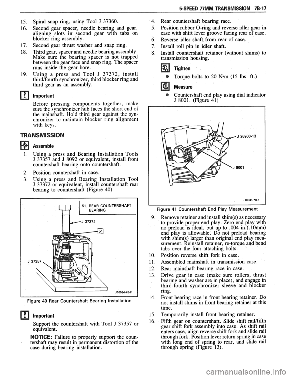
2. Position countershaft in case.
3. Using
a press and Bearing Installation Tool
J 37372 or equivalent, install countershaft rear
bearing to countershaft (Figure 40).
Figure 40 Rear Countershaft Bearing Installation
Support the countershaft with Tool J 37357 or
equivalent.
NOTICE: Failure to properly support the coun-
tershaft may result in permanent distortion of the
case during bearing installation. 4.
Rear countershaft bearing race.
5. Position rubber O-ring and reverse idler gear in
case with shift lever groove facing rear of case.
6. Reverse idler shaft from rear of case.
7. Install roll pin in idler shaft.
8. Install countershaft retainer (without shims) to
transmission housing.
Tighten
@ Torque bolts to 20 Wm (15 lbs. ft.)
Measure
@ Countershaft end play using dial indicator
J 8001. (Figure 41)
Figure 41 Countershaft End Play Measurement
9. Remove
retainer and install shim(s) as necessary
to provide proper end play. Zero end play with
no preload is ideal, but up to
.004 in.(. l0rnrn)
end play is allowable. Do not preload bearing
with
shim(s) larger than original end play mea-
surement. Reinstall retainer, re-torque and bend
tabs over the four attaching bolts.
10. Position reverse shift fork in case.
11. Assembled mainshaft
in transmission case.
12. Rear
mainshaft bearing race in case.
13. Drive gear
in case (make sure rollers, thrust
bearing and washer are in place), and engage in
third-fourth synchronizer sleeve and blocker
ring.
-
14. Front bearing race in
front bearing retainer. Do
not install shims in front bearing retainer at this
time.
15. Temporarily install front bearing retainer.
16. Fifth gear on countershaft. Slide shift railtfifth
gear shift fork assembly into case. As shift rail
enters case, align reverse shift fork and slide rail
through fork. Position lever return spring in case
with long end of spring to rear, and slide rail
through spring (Figure 13).
Page 1168 of 1825
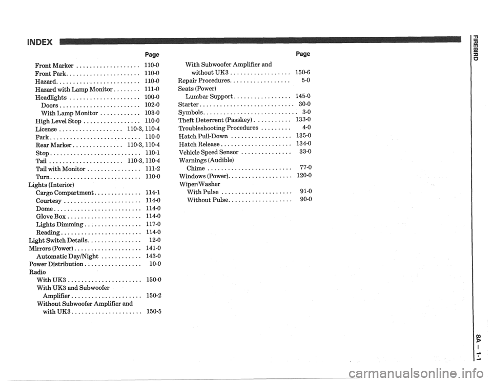
INDEX
Page
................... Front Marker 110-0
...................... Frontpark 110-0
......................... Hazard 110-0
........ Hazard with Lamp Monitor 111-0
..................... Headlights 100-0
........................ Doors 102-0
............ With Lamp Monitor 103-0
................. Nigh Level Stop 110-0
................... License 110.3,11 0.4
Park
........................... 110-0
............... Rear Marker 110.3,11 0.4
stop
........................... 110-1
...................... Tail 110.3,11 0.4
................ Tail with Monitor 111-2
Turn ........................... 110-0
Lights (Interior)
.............. Cargo Compartment 114-1
....................... Courtesy 114-0
.......................... Dome 114-0
...................... Glove Box 114-0
................. Lights Dimming 117-0
........................ Reading 114-0
................ Light Switch Details 12-0
.................... Mirrors (Power) 141-0
Automatic
DayINight ............ 143-0
................. Power Distribution 10-0
Radio
...................... With UK3 150-0
With
UK3 and Subwoofer
..................... Amplifier 15 0-2
Without Subwoofer Amplifier and
with
UK3 ..................... 150-5 With
Subwoofer Amplifier and
without UK3
..................
.................. Repair Procedures
Seats (Power)
Lumbar Support
.................
Starter ............................
........................... Symbols
........... Theft Deterlent (Passkey)
......... Troubleshooting Procedures
.................. Hatch Pull-Down
..................... Hatch Release
............... Vehicle Speed Sensor
Warnings (Audible)
Chime
.........................
................... Windows (Power)
WiperIWasher
With Pulse .....................
................... Without Pulse
Page
Page 1172 of 1825
INTRODUCTION
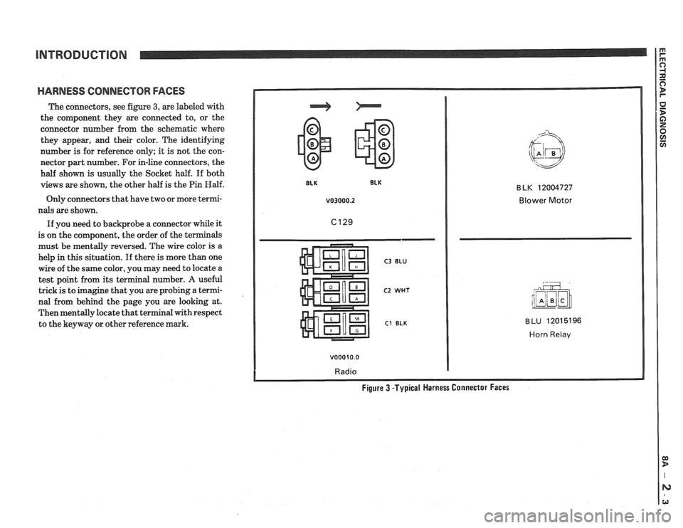
HARNESS CONNECTOR FACES
The connectors, see figure 3, are labeled with
the component they are connected to, or the
connector number from the schematic where
they appear, and their color. The identifying
number is for reference only; it is not the con-
nector part number. For in-line connectors, the
half shown is usually the Socket half. If both
views are shown, the other half is the Pin
Half.
Only connectors that have two or more termi-
nals are shown.
If you need to backprobe a connector while it
is on the component, the order of the terminals
must be mentally reversed. The wire color is a
help
in this situation. If there is more than one
wire of the same color, you may need to locate a
test point from its terminal number.
A useful
trick is to imagine that you are probing a termi-
nal from behind the page you are looking at.
Then mentally locate that terminal with respect
to the keyway or other reference mark.
v03000.2 Blower Motor
C3 BLU
C2 WHT
C1 BLK
v00010.0
Radio
BLU 12015196
Horn Relav
Figure 3 -Typical Harness Connector Faces
Page 1394 of 1825
WARNINGS AND ALARMS: CHIMES
TROUBLESHOOTING H lNTS
* Try the following checks before doing the
System Check.
1. Check the STOP HAZ Fuse by observing
the Hazard Lights Operation.
2. Check the GAGES Fuse by observing the
BRAKE Warning Indicator with the Park
Brake applied and the Ignition Switch in
RUN.
3. Check 6200 by operating the Cigar Lighter.
4. If the FASTEN BELT chime reminder and
indicator operate continuously, replace
Audio Alarm Assembly.
5. If the Park Lights are operating normally
and only the Lights-On reminder operates
incorrectly, replace the Audio Alarm Assem-
bly.
Go to System Check for a guide to normal
operation.
Go to System Diagnosis for diagnostic tests.
SYSTEM CHECK
* Use the System Check Table as a guide to
normal operation.
COMPONENT LOCATlON Page-Figure
Convenience Center
.............. Behind IIP, to right of steering column. ........ 201-10-A
Fuse Block.
..................... Behind LH side of IIP, below light switch. ...... 201-10-A
Ignition Key Warning Switch
...... Upper part of steering column
Seatbelt Switch. ................. In driver's seatbelt buckle
C210
(11 cavities) ................ Behind IIP, on RH lower side of steering column. 201-
9-A
6325 (1 cavity) .................. At LH door sill, base of center pillar
6200 .......................... Behind IIP, left of steering column ............ 201-10-A
S204. .......................... IIP harness, behind instrument cluster. ........ 201-10-A
S205. .......................... IIP harness, behind instrument cluster. ........ 201-10-A
S225. .......................... I/P harness, behind instrument cluster. ........ 201-10-A
S227. .......................... IIP harness, behind instrument cluster. ........ 201-10-A
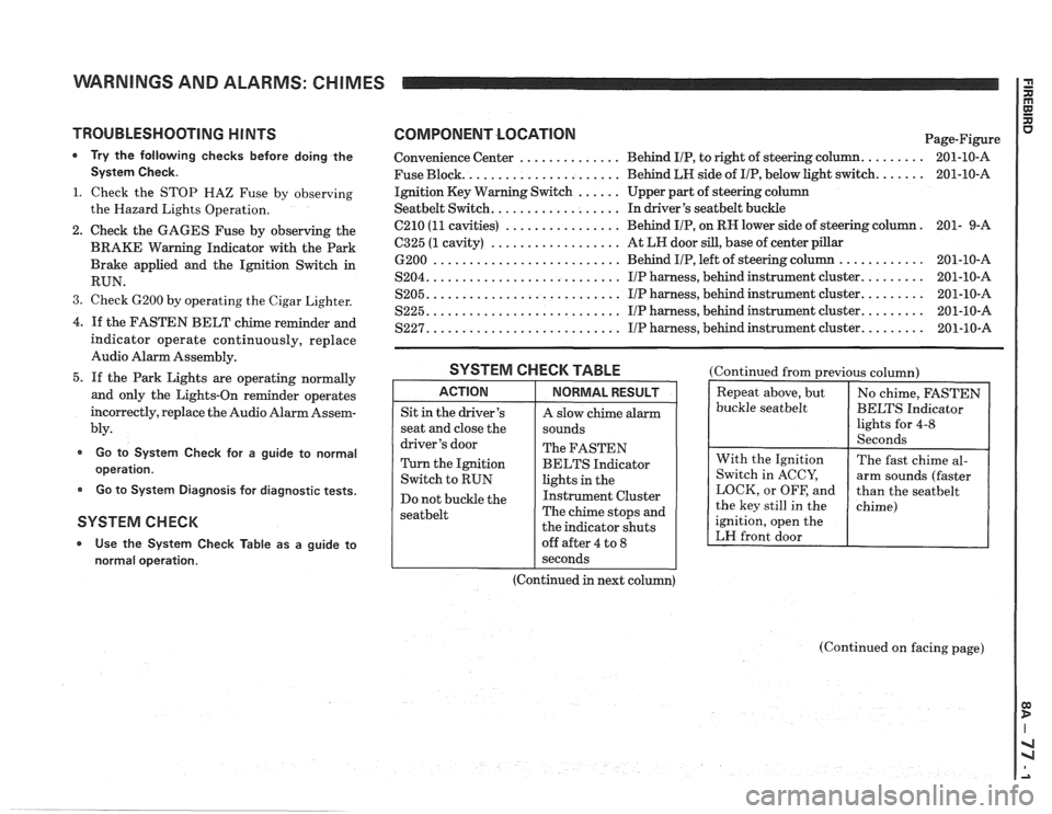
SYSTEM CHECK TABLE
ACTION
Sit in the driver's
seat and close the
driver's door
Turn the Ignition
Switch to RUN
Do not buckle the
seatbelt
NORMAL RESULT
A slow chime alarm
sounds
The FASTEN
BELTS Indicator
lights in the
Instrument Cluster
The chime stops and
the indicator shuts
off after 4 to
8
(Continued from previous column)
buckle
seatbelt
ignition, open the
LH front door
I seconds
(Continued in next column)
(Continued on facing page)