1988 PONTIAC FIERO key
[x] Cancel search: keyPage 986 of 1825
EXHAUST SYSTEM 6F-1
SEC"B0N 6F
EXHAUST SYSTEM
CAUTION: Exhaust system components should avoid overheating and possible damage to the
have enough clearance from the underbody to passenger compartment carpets.
................................. General Description 6F- 1 Hanger ............................................................ 6F- I
..................... ....................... Exhaust Pipe .. 6F- I Clamp ............................................................ 6F- I
Muffler .......................................................... 6F- 1 Catalytic Converter ......................................... 6F- 1
.......................... Resonator ........................... .. 6F- 1
GENERAL DESGRIP"F0N
When inspecting or replacing exhaust system
components, make sure there is adequate clearance
from all points on the underbody to avoid possible
overheating of the floor pan and possible damage to the
passenger compartment insulation and trim materials.
Check complete exhaust system and nearby body
areas and trunk lid for broken, damaged, missing or
mispositioned parts, open seams, holes, loose
connections or other deterioration which could permit
exhaust fumes to seep into the trunk or passenger
compartment. Dust or water in the trunk may be an
indication of a problem in one of these areas. Any
defects should be corrected immediately. To help
insure continued integrity, the exhaust system pipe
qever a
rearward of the muffler must be replaced whe.-
new muffler is installed.
EXHAUST PlPE
The exhaust manifold to crossover pipe
connections are of the ball type, thus eliminating the
need for gaskets.
MUFFLER
The mufflers are a tri-flow design. Some muffler
installations have a slot in the inlet and/or outlet pipe
which indexes to a key (tab) welded on the exhaust
and/or tail pipe to help maintain alignment.
RESONATOR
A resonator is used on some series exhaust
systems. It allows the use of mufflers with less back
pressure and provides for optimum tuning
characteristics of the exhaust system. The
installation of exhaust system supports is
very important as improperly installed supports can
cause annoying vibrations which are difficult to
diagnose.
CLAMP
Two methods are used for connecting exhaust
system slip joins, (1) clamp and
(2) weld. When
servicing a welded connection it should be cut and the
new connection clamped when installing replacement
parts. Also, coat slip joints with exhaust system sealer
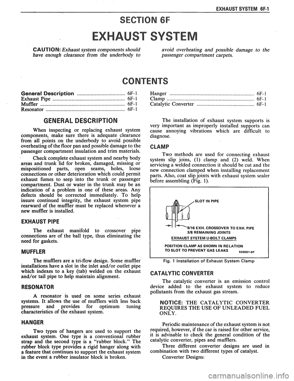
before assembling (Fig. 1).
SLOT IN PlPE
9/16 EXH. CROSSOVER TO EXH. PlPE 318 REMAINING JOINTS
EXHAUST SYSTEM U-BOLT CLAMPS
POSITION CLAMP AS SHOWN IN RELATION TO SLOT TO PREVENT GAS LEAKS ,,ooo,.,,
Fig. 1 Installation of Exhaust System Clamp
CATALYTIC CONVERTER
The catalytic converter is an emission control
device added to the exhaust system to reduce
pollutants from the exhaust gas stream.
NOTICE: THE CATALYTIC CONVERTER
REQUIRES THE USE OF UNLEADED FUEL
ONLY.
HANGER Periodic maintenance of the exhaust system is not
T~~ types of hangers are used to support the required, however, if the car is raised for other service,
exhaust system. one type is a conventional rubber it is advisable to check the general condition of the
strap and the second type is a "rubber block." The catalytic converter, pipes and mufflers.
rubber block type provides a rigid hanger along with Three
different converter designs are used in
a feature that continues to support the exhaust system combination with two different types of catalyst.
in the event a rubber insulator block is broken. Converter Designs:
Page 1050 of 1825
TORQUE CONVERTER CLUTCH (TCC)
DIAGNOSIS
To properly diagnose the Torque Converter
Clutch (TCC) system, perform all electrical
testing first and then the hydraulic testing. Refer
to the Torque Converter Section
6E2-C8 for
additional information.
The TCC is applied by fluid pressure which is
controlled by a solenoid located inside the Automatic
Transmission assembly. The solenoid is energized or
released by making or breaking an electrical circuit
through a combination of switches and sensors.
TCC Electrical Diagnosis
e For electrical diagnosis of TCC, refer to the
specific vehicle section in Section
8A, Electrical
Diagnosis.
e For diagnosis of emission control related
components of TCC, Refer to the specific section
of
6E, Driveability and Emissions.
e For the diagnosis of TCC Hydraulic Controls,
refer to the Procedure and Wiring Diagrams
provided in this section.
Functional Check Procedure
rn Inspect
1. Install a tachometer
2. Operate the vehicle until proper operating
temperature is reached
3. Drive vehicle at 50-55 mph (80-88 Km/h) with
light throttle (road load)
4. Maintaining throttle lightly touch the brake
pedal and check for a slight bump when the TCC
releases and a slight increase in engine RPM.
5. Release the brake, slowly accelerate and check for
a re-apply of the converter clutch and a slight
decrease in engine RPM.
Preliminary Checking Procedure
The purpose of the preliminary checking
procedure is to isolate external (electrical) problems
from internal (electrical or mechanical) ones.
Important
e Use only a scale type ohmmeter. High impedance
type ohmmeters and those with a digital readout
will not work.
e An ALCL scanner may be used to verify the
electrical circuit. Remember, a completed circuit
does not indicate that the solenoid will apply.
e Do not bench test using an automotive type
battery. Accidentally crossed wires will damage
the internal diodes of the TCC solenoid.
HYDRAULIC DIAGNOSIS 700-R4-61
External Controls
rn Inspect
e Connect voltmeter between transmission
connector and ground.
e Turn key "ON"
e If 0 or low voltage is found, refer to Sections 6E
and 8A for electrical diagnosis.
e If 12 volts are present at the connector, refer to
the TCC hydraulic diagnosis.
TORQUE CONVERTER EVALUATION
Torque Converter Stator
The Torque Converter Stator roller clutch can
have one of two different type malfunctions:
A. Stator Assembly freewheels in both
directions.
B. Stator Assembly remains locked up at all
times.
Condition A-Poor Acceleration Low Speed
The vehicle tends to have poor acceleration from
a standstill. At speeds above 30-35 mph (50-55
km/h),
the car may act normal. If poor acceleration is noted,
it should first be determined that the exhaust system
is not blocked, the engine timing is correct and the
transmission is in first
(1st) gear when starting out.
If the engine freely accelerates to high
r.p.m. in
"NEUTRAL" (N), it can be assumed that the engine
and exhaust system are normal. Checking for poor
performance in "Drive" and Reverse will help
determine if the stator is freewheeling at all times.
Condition B-Poor Acceleration High Speed
Engine r.p.m. and car speed limited or restricted
at high speeds. Performance when accelerating from a
standstill is normal. Engine may over-heat. Visual
examination of the converter may reveal a blue color
from over-heating.
If the converter has been removed, the stator
roller clutch can be checked by inserting a finger into
the splined inner race of the roller clutch and trying to
turn the race in both directions. The inner race should
turn freely clockwise, but not turn or be very difficult
to turn counterclockwise.
The Converter Should Be Replaced If:
e Leaks externally, such as at the hub weld area.
e Converter has an imbalance which cannot be
corrected. (Refer to Converter Vibration Test
Procedure).
e Converter is contaminated with engine coolant
containing antifreeze.
The Converter Should Not Be Replaced If:
e The oil has an odor, is discolored, and there is no
evidence of metal or clutch facing particles.
e The threads in one or more of the three converter
bolt holes are damaged.
- Correct with thread insert. (Refer to Section
6A).
Page 1070 of 1825
AUTOMATIC TRANSMISSION 700-R4-19
- Steel for heat damage or surface finish
damage
Reaction carrier assembly (681) for
- pinion gear damage
- excessive pinion washer wear (end play -20-.
61 mm/.008-.024 in.)
- proper pinion staking
- keystoned pinion gears (pinions must turn
free)
- damaged or worn thrust bearing
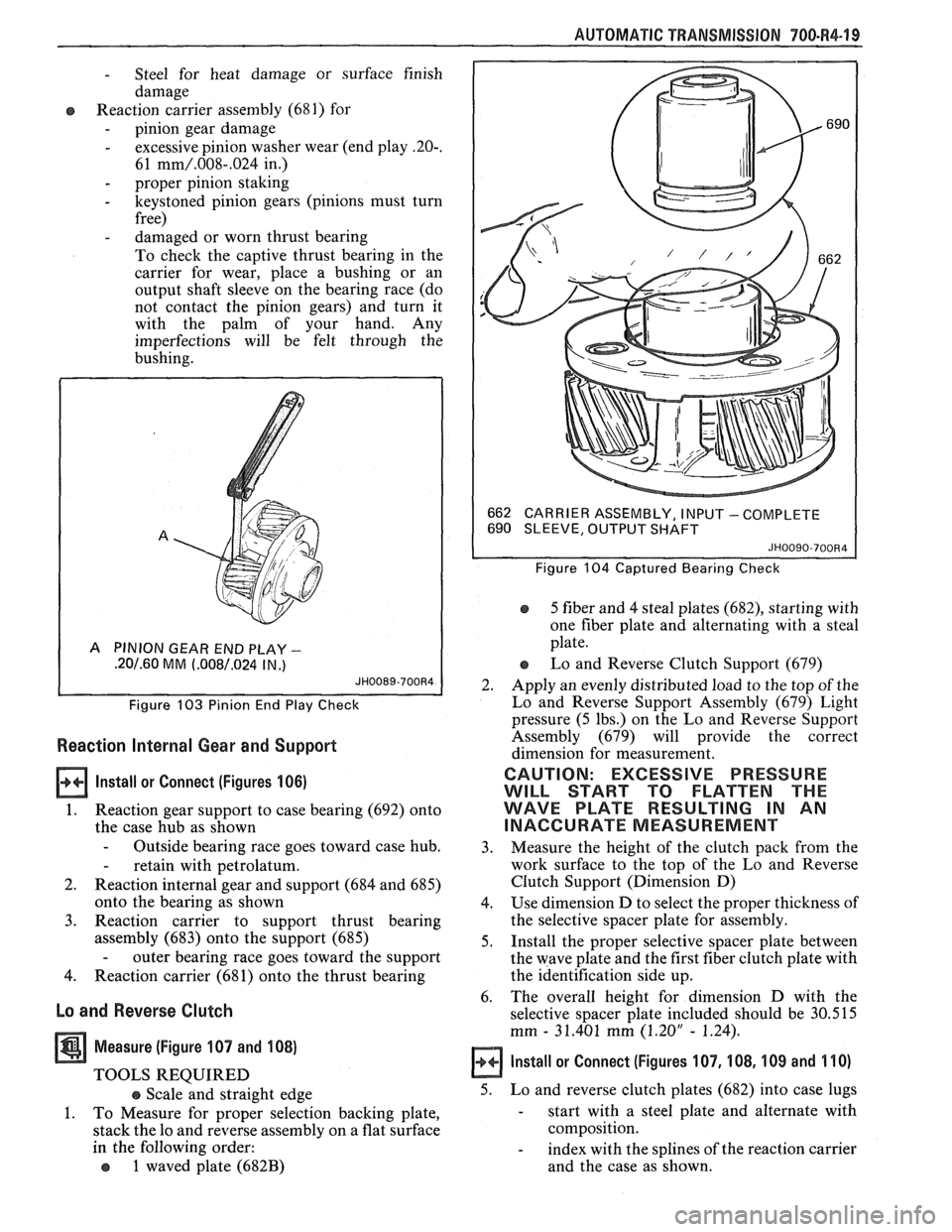
To check the captive thrust bearing in the
carrier for wear, place a bushing or an
output shaft sleeve on the bearing race (do
not contact the pinion gears) and turn it
with the palm of your hand. Any
imperfections will be felt through the
bushing.
A PINION GEAR END PLAY -
.20/.60 MM (.008/.024 IN .)
Figure 103 Pinion End Play Check
Reaction Internal Gear and Support
lnstall or Connect (Figures 106)
1. Reaction gear support to case bearing (692) onto
the case hub as shown
- Outside bearing race goes toward case hub.
- retain with petrolatum.
2. Reaction internal gear and support (684 and 685)
onto the bearing as shown
3. Reaction carrier to support thrust bearing
assembly (683) onto the support (685)
- outer bearing race goes toward the support
4. Reaction carrier (681) onto the thrust bearing
Lo and Reverse Clutch
Measure (Figure 107 and 108)
TOOLS REQUIRED
e Scale and straight edge
1. To Measure for proper selection backing plate,
stack the lo and reverse assembly on a flat surface
in the following order:
o 1 waved plate (682B)
662
CARRIER ASSEMBLY, I NPU'T - COMPLETE
690 SLEEVE, OUTPUT SHAFT
JH0090-700R4
Figure 104 Captured Bearing Check
5 fiber and 4 steal plates (682), starting with
one fiber plate and alternating with a steal
plate.
Lo and Reverse Clutch Support (679)
2. Apply an evenly distributed load to the top of the
Lo and Reverse Support Assembly (679) Light
pressure (5 lbs.) on the Lo and Reverse Support
Assembly (679) will provide the correct
dimension for measurement.
CAUTION: EXCESSIVE PRESSURE
WILL START TO FLATTEN THE
WAVE PLATE RESULTING IN AN
INACCURATE MEASUREMENT
3. Measure
the height of the clutch pack from the
work surface to the top of the Lo and Reverse
Clutch Support (Dimension D)
4. Use dimension D to select the proper thickness of
the selective spacer plate for assembly.
5. Install the proper selective spacer plate between
the wave plate and the first fiber clutch plate with
the identification side up.
6. The
overall height for dimension D with the
selective spacer plate included should be 30.515
mm
- 31.401 mm (1.20" - 1.24).
Install or Connect (Figures 107, 108, 109 and 110)
5. Lo and reverse clutch plates (682) into case lugs
- start with a steel plate and alternate with
composition.
- index with the splines of the reaction carrier
and the case as shown.
Page 1075 of 1825
"1QO-R4-24 AUTOMATIC TRANSMISSION
- cracks
- damaged spline or gear teeth
Input carrier to reaction shaft thrust bearing
(663) for wear or damage
Ouput shaft (687)
- plugged or restrictred lube passages
- damaged splines or ring groove
- damaged governor drive gear teeth
- burrs or damage to the front of the shaft at
seal area. (Polish with crocus cloth if
necessary)
- burrs or damage to bearing journals
- damaged teeth on speed sensor rotor
Internal Transmission Speed Sensor Rotor
REMOVE ONLY IF DAMAGED
TOOLS REQUIRED:
J-2 1427-0 1 speedometer gear puller adapter
5-8433 speedometer gear puller
J-36352 speedometer gear installater
& "C"
washer
Mechanical press
1. Install J-21427 with J-8433 and remove rotor.
2. Place new rotor over output shaft.
3. Place J-36352-1 in groove on output shaft.
- DO NOT REUSE ROTOR
4. Place 5-36352-2 on shaft and press to make
contact with
5-36352- 1.
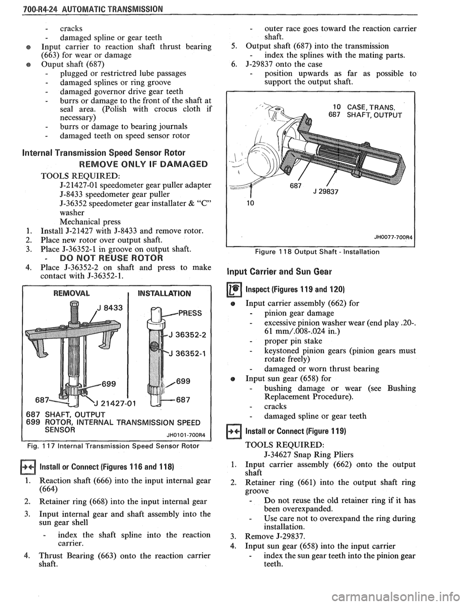
L TRANSMISSION SPEED
Fig. 1 17 Internal f ransmission Speed Sensor Rotor
Install or Connect (Figures 1 16 and 1 18)
1. Reaction shaft (666) into the input internal gear
(664)
2. Retainer ring (668) into the input internal gear
3. Input internal gear and shaft assembly into the
sun gear shell
- index the shaft spline into the reaction
carrier.
4. Thrust Bearing (663) onto the reaction carrier
shaft.
- outer race goes toward the reaction carrier
shaft.
5. Output shaft (687) into the transmission
- index the splines with the mating parts.
6. J-29837 onto the case
- position upwards as far as possible to
support the output shaft.
Figure 1 18 Output Shaft - Installation
Input Carrier and Sun Gear
Inspect (figures 1 19 and 120)
e Input carrier assembly (662) for
- pinion gear damage
- excessive pinion washer wear (end play 20-.
61 mm/.008-.024 in,)
- proper pin stake
- keystoned pinion gears (pinion gears must
rotate freely)
- damaged or worn thrust bearing
e Input sun gear (658) for
- bushing damage or wear (see Bushing
Replacement Procedure).
- cracks
- damaged spline or gear teeth
Install or Connect (Figure 1 19)
TOOLS REQUIRED:
5-34627 Snap Ring Pliers
1. Input carrier assembly (662) onto the output
shaft
2. Retainer ring (661) into the output shaft ring
groove
- Do not reuse the old retainer ring if it has
been overexpanded.
- Use care not to overexpand the ring during
installation.
3. Remove J-29837.
4. Input sun gear (658) into the input carrier
- index the sun gear teeth into the pinion gear
teeth.
Page 1123 of 1825
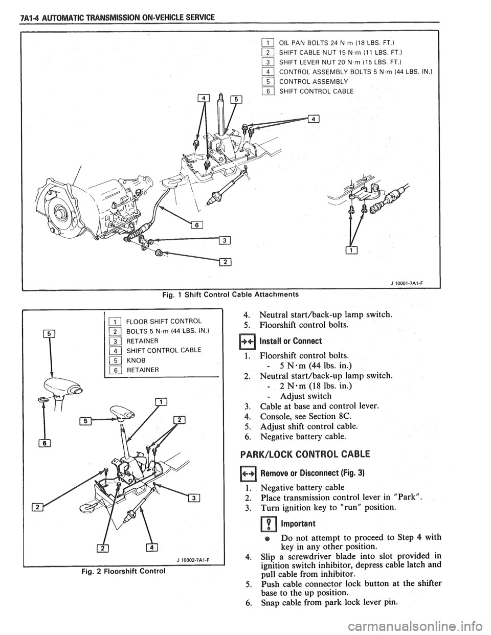
7A44 AUTOMATIC "PANSMISSION ON-VEHICLE SERVICE
Fig. 1 Shift Control Cable Attachments
4. Neutral starthack-up lamp switch.
5. Floorshift control bolts.
Install or Connect
1. Floorshift control bolts.
- 5 N-m (44 lbs. in.)
2. Neutral starthack-up lamp switch.
- 2 N.m (18 lbs. in.)
- Adjust switch
3. Cable at base and control lever.
4. Console, see Section 8C.
5. Adjust shift control cable.
6. Negative battery cable.
PARK/LOCK CONTROL CABLE
Remove or Disconnect (Fig. 3)
1. Negative battery cable
2. Place transmission control lever in "Park".
3. Turn ignition key to "run" position.
Important
s Do not attempt to proceed to Step 4 with
key in any other position.
4. Slip a screwdriver blade into slot provided in
ignition switch inhibitor, depress cable latch and
pull cable from inhibitor.
5. Push cable connector lock button at the shifter
base to the up position.
6. Snap cable from park lock lever pin.
Page 1124 of 1825
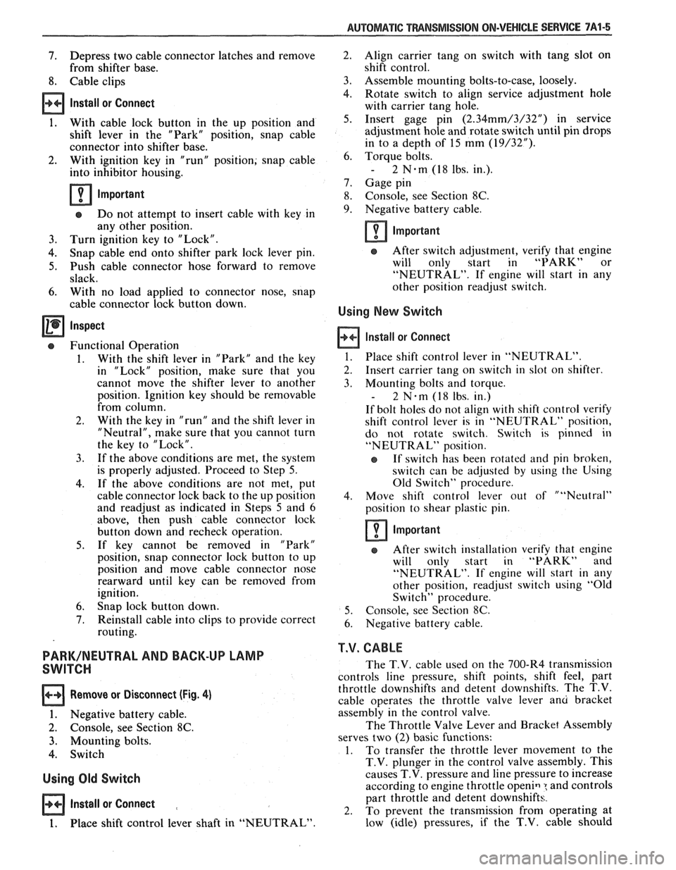
AUTOMATIC TMNSMISSION ON-VEHICLE SERVICE 7A1-5
7. Depress two cable connector latches and remove
from shifter base.
8. Cable clips
Install or Connect
1. With cable lock button in the up position and
shift lever in the "Park" position, snap cable
connector into shifter base.
2. With ignition key in "run" position; snap cable
into inhibitor housing.
Important
e Do not attempt to insert cable with key in
any other position.
3. Turn ignition key to "Lock".
4. Snap cable end onto shifter park lock lever pin.
5. Push cable connector hose forward to remove
slack.
6. With no load applied to connector nose, snap
cable connector lock button down.
Inspect
Functional Operation
1. With the shift lever in "Park" and the key
in "Lock" position, make sure that you
cannot move the shifter lever to another
position. Ignition key should be removable
from column.
2. With the key in "run" and the shift lever in
"Neutral", make sure that you cannot turn
the key to "Lock".
3. If the above conditions are met, the system
is properly adjusted. Proceed to Step
5.
4. If the above conditions are not met, put
cable connector lock back to the up position
and readjust as indicated in Steps
5 and 6
above, then push cable connector lock
button down and recheck operation.
5. If key cannot be removed in "Park"
position, snap connector lock button to up
position and move cable connector nose
rearward until key can be removed from
ignition.
6. Snap lock button down.
7. Reinstall cable into clips to provide correct
routing.
PARK/NEUTRAL AND BACK-UP LAMP
SWITCH
Remove or Disconnect (Fig. 4)
1. Negative battery cable.
2. Console, see Section 8C.
3. Mounting bolts.
4. Switch
Using Old Switch
Install or Connect :
1. Place shift control lever shaft in "NEUTRAL" Align
carrier tang on switch with tang slot on
shift control.
Assemble mounting bolts-to-case, loosely.
Rotate switch to align service adjustment hole
with carrier tang hole.
Insert gage pin
(2.34mm/3/32") in service
adjustment hole and rotate switch until pin drops
in to a depth of 15 mm
(19/32").
Torque bolts.
- 2 N.m (1 8 lbs. in.).
Gage pin
Console, see Section
8C.
Negative battery cable.
Important
After switch adjustment, verify that engine
will only start in
"PARK" or
"NEUTRAL". If engine will start in any
other position readjust switch.
Using New Switch
Install or Connect
1. Place shift control lever in "NEUTRAL".
2. Insert carrier tang on switch in slot on shifter.
3. Mounting bolts and torque.
- 2 N-m (18 lbs. in.)
If bolt holes do not align with shift control verify
shift control lever is in "NEUTRAL" position,
do not rotate switch. Switch is pinned in
"NEUTRAL" position.
e If switch has been rotated and pin broken,
switch can be adjusted by using the Using
Old Switch" procedure.
4. Move shift control lever out of ""Neutral"
position to shear plastic pin.
Important
After switch installation verify that engine
will only start in "PARK" and
"NEUTRAL". If engine will start in any
other position, readjust switch using "Old
Switch" procedure.
5. Console, see Section
8C.
6. Negative battery cable.
T.V. CABLE
The T.V. cable used on the 700-R4 transmission
controls line pressure, shift points, shift feel, part
throttle downshifts and detent downshifts. The T.V.
cable operates the throttle valve lever
anu bracket
assembly in the control valve.
The Throttle Valve Lever and Bracket Assembly
serves two
(2) basic functions:
1. To
transfer the throttle lever movement to the
T.V. plunger in the control valve assembly. This
causes T.V. pressure and line pressure to increase
according to engine throttle
openiq : and controls
part throttle and detent downshifts.
2. To prevent the transmission from operating at
low (idle) pressures, if the
T.V. cable should
Page 1138 of 1825
SECTION 7B
5-SPEED 77MM TRANSM
RPO-M39 MK6 AND MBI
CONTENTS
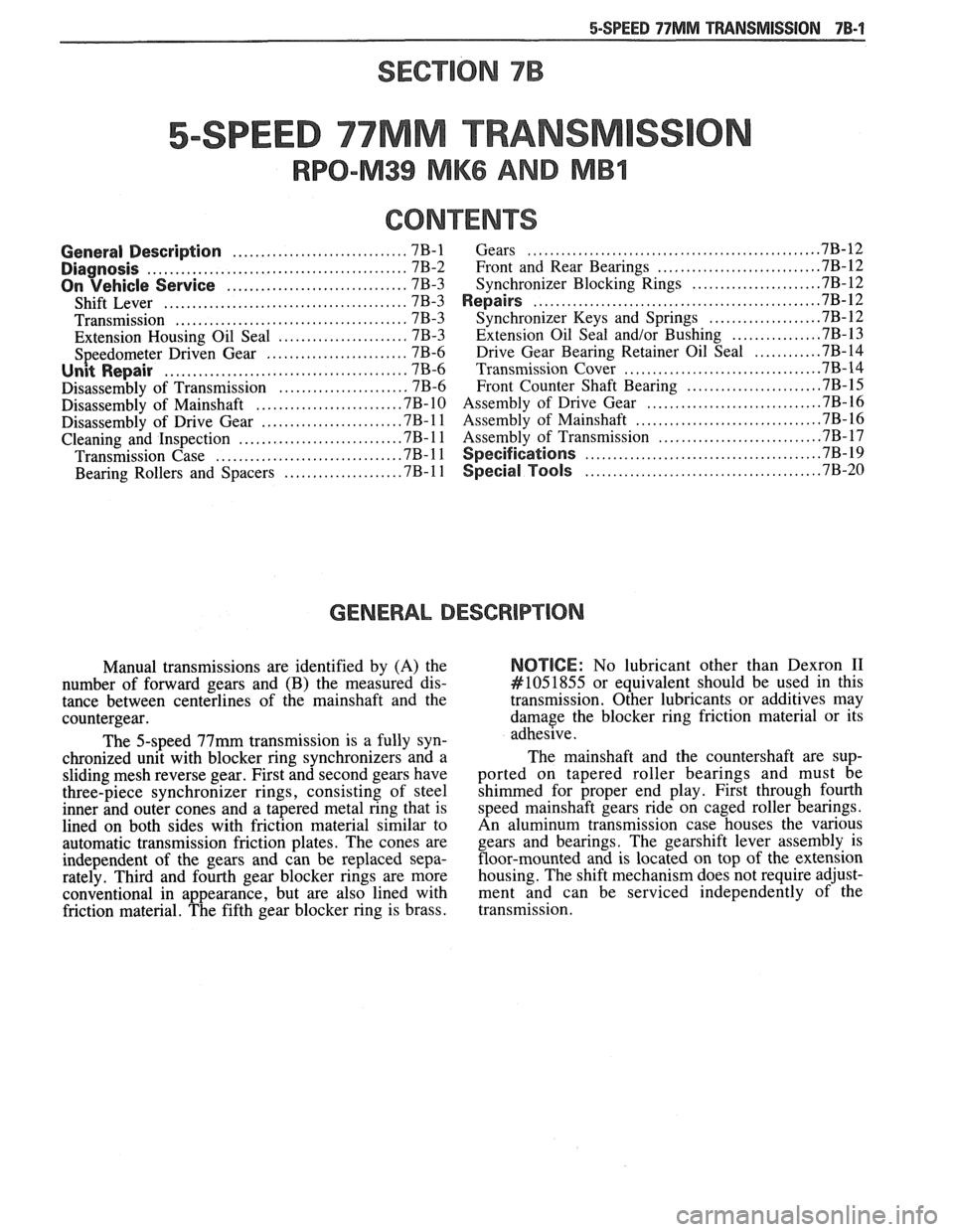
........................... ................... ............................... General Description 7B-1 Gears ... 7B-12 .......................... .............................................. Diagnosis 7B-2 Front and Rear Bearings ..7B-12 ...................... ................................ On Vehicle Service 7B-3 Synchronizer Blocking Rings .7B-12 .................................................. ........................................... Shift Lever 7B-3 Repairs ,7B-12
......................................... ................... Transmission 7B-3 Synchronizer Keys and Springs .7B- 12
....................... ............... Extension Housing Oil Seal 7B-3 Extension
Oil Seal and/or Bushing .7B-13
Speedometer Driven Gear ......................... 7B-6
Drive Gear Bearing Retainer Oil Seal ............ 7B-14
........................................... .................................. Unit Repair 7B-6 Transmission Cover .7B-14
....................... ....................... Disassembly of Transmission 7B-6 Front Counter Shaft Bearing .7B-15 .............................. ......................... Disassembly of Mainshaft .7B- 10 Assembly of Drive Gear .7B- 16 ............................... ........................ Disassembly of Drive Gear ,7B- 1 1 Assembly of Mainshaft 7B- 16 ............................. ............................ Cleaning and Inspection ,7B-11 Assembly of Transmission 7B-17 ........................................ ............................... Transmission Case .7B-11 Specifications .7B-19
....................... .......... .................... Bearing Rollers and Spacers .7B-11 Special Tools ... .7B-20
GENERAL DESCRIPTION
Manual transmissions are identified by (A) the
number of forward gears and
(B) the measured dis-
tance between centerlines of the mainshaft and the
countergear.
The 5-speed 77mm transmission is a fully syn-
chronized unit with blocker ring synchronizers and a
sliding mesh reverse gear. First and second gears have
three-piece synchronizer rings, consisting of steel
inner and outer cones and
a tapered metal ring that is
lined on both sides with friction material similar to
automatic transmission friction plates. The cones are
independent of the gears and can be replaced sepa-
rately. Third and fourth gear blocker rings are more
conventional in appearance, but are also lined with
friction material. The fifth gear blocker ring is brass.
NOTICE: No lubricant other than Dexron I1
#I051855 or equivalent should be used in this
transmission. Other lubricants or additives may
damage the blocker ring friction material or its
adhesive.
The mainshaft and the countershaft are sup-
ported on tapered roller bearings and must be
shimmed for proper end play. First through fourth
speed mainshaft gears ride on caged roller bearings.
An aluminum transmission case houses the various gears and bearings. The gearshift lever assembly is
floor-mounted and is located on top of the extension
housing. The shift mechanism does not require adjust-
ment and can be serviced independently of the
transmission.
Page 1142 of 1825
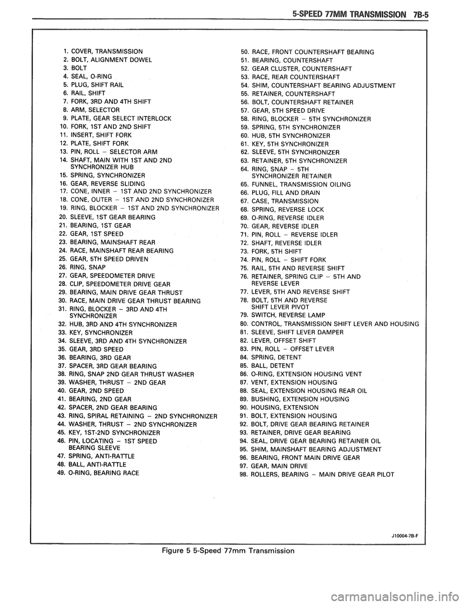
5-SPEED 97MM TRANSMISSION 7B-5
1. COVER, TRANSMISSION
50. RACE, FRONT COUNTERSHAFT BEARING
2. BOLT, ALIGNMENT DOWEL
51. BEARING, COUNTERSHAFT
52. GEAR CLUSTER, COUNTERSHAFT
4. SEAL, O-RING
53. RACE, REAR COUNTERSHAFT
5. PLUG, SHIFT
RAIL 54. SHIM, COUNTERSHAFT BEARING ADJUSTMENT
6. RAIL, SHIFT
55. RETAINER, COUNTERSHAFT
7. FORK, 3RD AND 4TH SHIFT
56. BOLT, COUNTERSHAFT RETAINER
8. ARM, SELECTOR
57. GEAR, 5TH SPEED DRIVE
9. PLATE, GEAR SELECT INTERLOCK
58. RING, BLOCKER
- 5TH SYNCHRONIZER
10. FORK,
1ST AND 2ND SHIFT
59. SPRING, 5TH SYNCHRONIZER
11. INSERT, SHIFT FORK
60. HUB, 5TH SYNCHRONIZER
12. PLATE, SHIFT FORK
61. KEY, 5TH SYNCHRONIZER
13. PIN, ROLL
- SELECTOR ARM
62. SLEEVE, 5TH SYNCHRONIZER
14. SHAFT,
MAIN WITH 1ST AND 2ND
63. RETAINER, 5TH SYNCHRONIZER
SYNCHRONIZER HUB
64. RING, SNAP
- 5TH
15. SPRING, SYNCHRONIZER SYNCHRONIZER RETAINER
16. GEAR, REVERSE SLIDING
65. FUNNEL, TRANSMISSION OILING
17. CONE, INNER
- 1ST AND 2ND SYNCHRONIZER
66. PLUG, FILL AND DRAIN
18. CONE, OUTER - 1ST AND 2ND SYNCHRONIZER
67. CASE, TRANSMISSION
19. RING, BLOCKER
- 1ST AND 2ND SYNCHRONIZER
68. SPRING, REVERSE LOCK
20. SLEEVE,
1ST GEAR BEARING
69. O-RING, REVERSE IDLER
21. BEARING,
1ST GEAR
70. GEAR, REVERSE IDLER
22. GEAR,
1ST SPEED 71. PIN, ROLL - REVERSE IDLER
23. BEARING, MAINSHAFT REAR
72. SHAFT, REVERSE IDLER
24. RACE,
MAINSHAFT REAR BEARING
73. FORK, 5TH SHIFT
25. GEAR, 5TH SPEED DRIVEN
74. PIN, ROLL - SHIFT FORK
26. RING, SNAP
75. RAIL, 5TH AND REVERSE SHIFT
27. GEAR, SPEEDOMETER DRIVE
76. RETAINER, SPRING CLIP - 5TH AND
28. CLIP, SPEEDOMETER DRIVE GEAR REVERSE LEVER
29. BEARING,
MAIN DRIVE GEAR THRUST 77.
LEVER, 5TH AND REVERSE SHIFT
30. RACE,
MAIN DRIVE GEAR THRUST BEARING 78. BOLT, 5TH
AND REVERSE
31. RING, BLOCKER
- 3RD AND 4TH SHIFT
LEVER PIVOT
SYNCHRONIZER 79. SWITCH, REVERSE LAMP
32. HUB, 3RD AND 4TH SYNCHRONIZER 80.
CONTROL, TRANSMISSION SHIFT LEVER AND HOUSING
33. KEY, SYNCHRONIZER 81.
SLEEVE, SHIFT LEVER DAMPER
34. SLEEVE, 3RD AND 4TH SYNCHRONIZER 82.
LEVER, OFFSET SHIFT
35. GEAR, 3RD SPEED 83. PIN, ROLL
- OFFSET
LEVER
36. BEARING, 3RD GEAR 84.
SPRING, DETENT
37. SPACER, 3RD GEAR BEARING 85.
BALL, DETENT
38. RING, SNAP 2ND GEAR THRUST WASHER 86.
O-RING, EXTENSION HOUSING VENT
39. WASHER, THRUST
- 2ND GEAR 87. VENT, EXTENSION HOUSING
40. GEAR, 2ND SPEED 88. SEAL, EXTENSION HOUSING REAR OIL
41. BEARING, 2ND GEAR 89. BUSHING, EXTENSION HOUSING
42. SPACER,
2ND GEAR BEARING 90.
HOUSING, EXTENSION
43. RING, SPIRAL RETAINING
- 2ND SYNCHRONIZER 91. BOLT, EXTENSION HOUSING
44. WASHER, THRUST - 2ND SYNCHRONIZER 92.
BOLT, DRIVE GEAR BEARING RETAINER
45. KEY, 1ST-2ND SYNCHRONIZER 93.
RETAINER, DRIVE GEAR BEARING
46. PIN, LOCATING
- 1ST SPEED 94. SEAL, DRIVE GEAR BEARING RETAINER OIL
BEARING SLEEVE
95. SHIM,
MAINSHAFT BEARING ADJUSTMENT
47. SPRING, ANTI-RAlTLE 96. BEARING, FRONT MAIN DRIVE GEAR 48. BALL, ANTI-RATTLE
97. GEAR, MAIN DRIVE
49. O-RING, BEARING RACE
98. ROLLERS, BEARING
- MAIN DRIVE GEAR PILOT
Figure 5 &Speed 99mm Transmission