1988 PONTIAC FIERO key
[x] Cancel search: keyPage 484 of 1825
ENGINE ELECTRICAL 6D-3
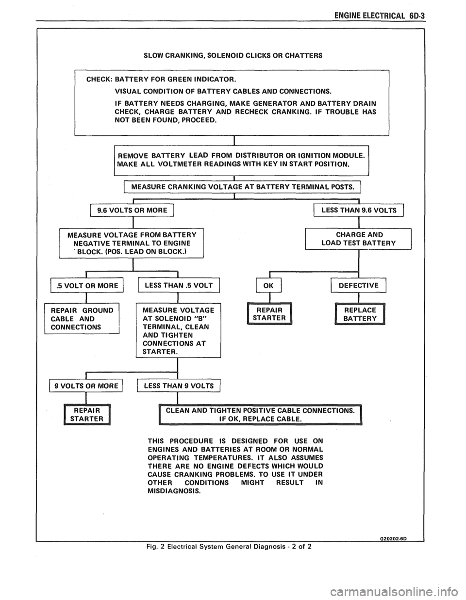
SLOW CRANKING, SOLENOID CLICKS OR CHATTERS
VISUAL CONDITION OF BATTERY CABLES AND CONNECTIONS.
IF BATTERY NEEDS CHARGING, MAKE GENERATOR AND BATTERY DRAIN
CHECK, CHARGE BATTERY AND RECHECK CRANKING. IF TROUBLE HAS
NOT BEEN FOUND, PROCEED.
AKE ALL VOLTMETER READINGS
WITH KEY IN START POSITION.
CABLE AND AT SOLENOID
"8"
TERMINAL, CLEAN
AND TIGHTEN
CONNECTIONS AT
THIS PROCEDURE IS DESIGNED FOR USE ON
ENGINES AND BATTERIES AT ROOM OR NORMAL
OPERATING TEMPERATURES. IT ALSO ASSUMES
THERE ARE NO ENGINE DEFECTS WHICH WOULD
CAUSE CRANKING PROBLEMS. TO USE IT UNDER
OTHER CONDITIONS MIGHT RESULT IN
MISDIAGNOSIS.
Fig. 2 Electrical System General Diagnosis - 2 of 2
Page 490 of 1825
DRIVEABILITY AND EMISSIONS 5.OL (VIN E) 6E2-5
ALL NEW GENERAL MOTORS VEHICLES ARE CERTIFIED BY THE UNITED STATES
ENVIRONMENTAL PROTECTION AGENCY AS CONFORMING TO THE REQUIREMENTS OF THE
REGULATIONS FOR THE CONTROL OF AIR POLLUTION FROM NEW MOTOR VEHICLES.
THlS
CERTIFICATION IS CONTINGENT ON CERTAIN ADJUSTMENTS BEING SET TO FACTORY
STANDARDS. IN MOST CASES, THESE ADJUSTMENT POINTS EITHER HAVE BEEN
PERMANENTLY SEALED
AND/OR MADE INACCESSIBLE TO PREVENT INDISCRIMINATE OR
ROUTINE ADJUSTMENT IN THE FIELD. FOR
THlS REASON, THE FACTORY PROCEDURE FOR
TEMPORARILY REMOVING PLUGS, CAPS, ETC., FOR PURPOSES OF SERVICING THE PRODUCT,
MUST BE STRICTLY FOLLOWED AND, WHEREVER PRACTICABLE, RETURNED TO
THE
ORIGINAL INTENT OF THE DESIGN.
INTRODUCTION
GENERAL DESCRIPTION DIAGNOSIS PROCEDURE
This section applies to engines which have a fuel
injector mounted above a throttle body assembly. The
entire assembly is mounted to the intake manifold and
is referred to as "Throttle Body Injection".
These engines have controls to reduce exhaust
emissions, while maintaining good driveability and
fuel economy.
An engine control module
(ECM) is the heart of
this control system and has sensors used to provide
information about engine operation and the various
systems it controls. Details of basic operation,
diagnosis, functional checks, and on-vehicle service
are covered in Section
"C", Component Systems.
The
ECM has the ability to do some diagnosis of
itself, and of other parts of the system. When it finds a
problem,
it lights a "Service Engine Soon" light on the
instrument panel and a trouble code will be stored in
the ECM memory. This does not mean that the engine
should be stopped right away, but that the cause of the
light coming
"ON" should be checked as soon as
reasonably possible. The
following
sectionds) are written for specific
engine applications and are clearly indentified. Be
sure to use only the section which applies to the
engine family being diagnosed.
Before using this section of the manual, you
should be familiar with the information and the
proper diagnosing procedures as described in Section
"6E". If the proper diagnosis procedures are not
follo\l;red, as described in Section "6En, it may result in
unnecessary replacement of good parts.
Trouble tree charts incorporate diagnosis
procedures using an
ALDI, "Scan" tool, where
possible. The "Scan" tool has the ability to save time
in diagnosis and prevent the replacement of good
parts. The key to using; the "Scan" tool
successfully for diagnosis lies in the technician's
abilitv to understand the system
he is try in^ to
diagnose,
as well as an understanding of the
"Scan" tool's limitations. See Section
6E for more
information.
Page 505 of 1825
6E2-A-114 5.OL (VIN E) DRIVEABILITY AND EMISSIONS
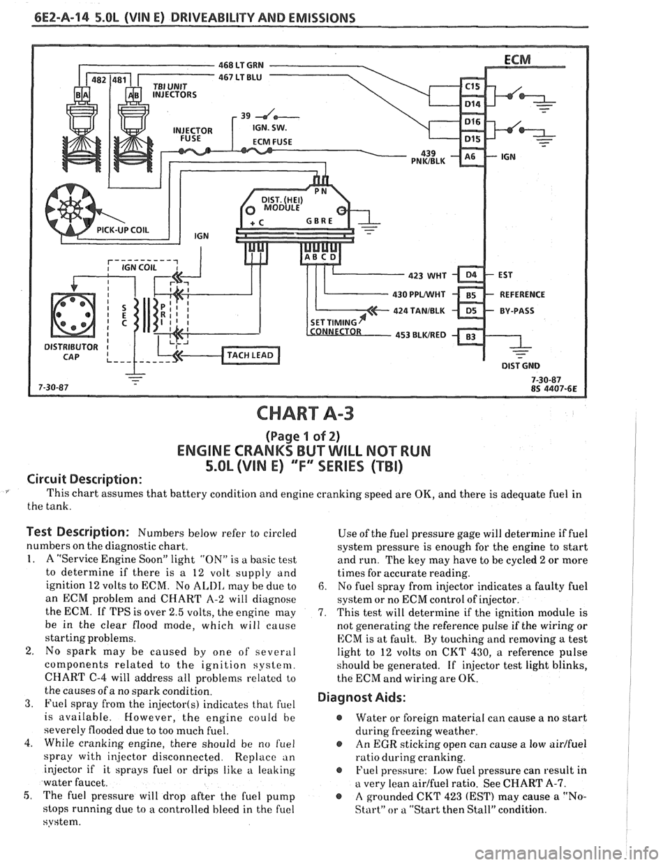
CHART A-3
(Page I of 2)
ENGINE CRANKS BUT WILL NQ"TRUN
5.OL (VIM E) "F"" SERlES (TBI)
Circuit Description:
This chart assumes that battery condition and engine cranking speed are OK, and there is adequate fuel in
the tank.
Test Description: Numbers below refer to circled
numbers on the diagnostic chart.
1. A "Service Engine Soon" light "ON" is a basic test
to determine if there is a 12 volt supply and
ignition 12 volts to ECM. No
ALIII, may be due to
an ECM problem and CHART A-2 will diagnose
the ECM. If TPS is over 2.5 volts, the engine may
be in the clear flood mode, which will cause
starting problems.
2. No spark may be caused by one of several
components related to the ignition system.
CHART
C-4 will address all problems related to
the causes of a no spark condition.
3. Fuel spray from the injector(s) indicates that fuel
is available. However, the engine could be
severely flooded due to too much fuel.
4. While cranking engine, there should be no
f~lel
spray with injector disconnected. Replace an
injector if it sprays fuel or drips like a leaking
water faucet.
5, The fuel pressure will drop after the fuel pump
stops running due to
a controlled bleed in the fuel
system. Use
of the fuel pressure gage will determine
if fuel
system pressure is enough for the engine to start
and run. The key may have to be cycled
2 or more
times for accurate reading.
6. No fuel spray from injector indicates a faulty fuel
system or no ECM control of injector.
7. This test will determine if the ignition module is
not generating the reference pulse if the wiring or
ECM is at fault. By touching and removing
a test
light to 12 volts on CKT 430,
a reference pulse
should be generated. If
injector test light blinks,
the ECM and wiring are
OK.
Diagnost Aids:
@ Water or foreign material can cause a no start
during freezing weather.
@ An EGR sticking open can cause a low airlfuel
ratio during cranking.
@ Fuel pressure: Low fuel pressure can result in
a very lean airlfuel ratio. See CHART A-7.
@ A grounded CKT 423 (EST) may cause a "No-
Start" or a "Start then Stall" condition.
Page 509 of 1825
6EZ-Pa-18 5.OL (VIN E) DRIVEABILITY AND EMISSIONS
FUEL PUMP
RELAY CONN.
465 DK GRNMIHT
450 BLWHT
FUEL PUMP
BATTERY JUNCTION TEST TERM. BULKHEAD BODY CONNECTOR
BLOCK
(1 2 VOLT) CONNECTOR
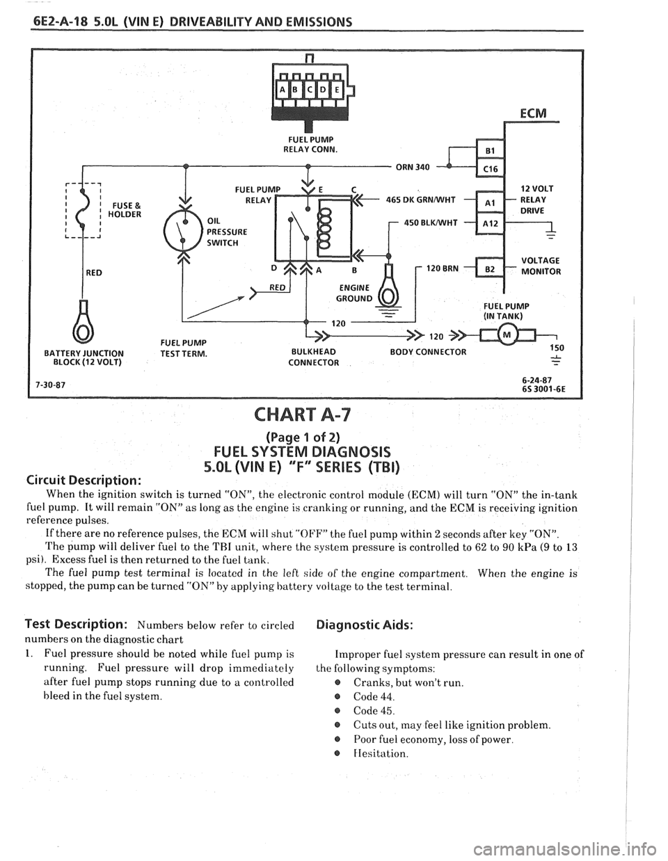
CHART A-7
(Page 1 of 2)
FUEL SYSTEM DlAGNOSlS
5.0L (VIN E) "F"" SERIES (TBI)
Circuit Description:
When the ignition switch is turned "ON", the electronic control module (ECM) will turn "ON" the in-tank
fuel pump. It will remain "ON"
as long as the engine is cranking or running, and the ECM is receiving ignition
reference pulses.
If there are no reference pulses, the ECM will shut
"OI'F" the fuel pump within 2 seconds after key "ON".
The pump will deliver fuel to the THI unit, where the system pressure is controlled to 62 to 90 kPa (9 to 13
psi). Excess fuel is then returned to the fuel tank.
The fuel pump test terminal is located in the left side of the engine compartment. When the engine is
stopped, the pump can be turned "ON" by applying battery voltage to the test terminal.
lest Description: Numbers below refer to circled Diagnostic Aids:
numbers on the diagnostic chart
1. Fuel pressure should be noted while fuel pump is Improper fuel system pressure can result in one of
running. Fuel pressure will drop immediately the following symptoms:
after fuel pump stops running due to a controlled
e Cranks, but won't run.
bleed in the fuel system.
@ Code 44.
@ Code 45.
@ Cuts out, may feel like ignition problem.
@ Poor fuel economy, loss of power.
FIesitation.
Page 543 of 1825
PNWBLK 439
CODE 53
VEHICLE ANTI-THEFT SYSTEM (VATS) CIRCUIT
5.OL (VIM E) "F" SERIES (TBI)
Circuit Description:
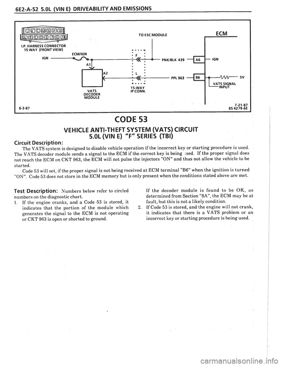
The VATS system is designed to disable vehicle operation if the incorrect key or starting procedure is used.
The VATS decoder module sends a signal to the ECM if the correct key is being
:sed. If the proper signal does
not reach the ECM on CKT 963, the ECM will not pulse the injectors
"ON" and thus not allow the vehicle to be
started. Code
53 will set, if the proper signal is not being received at ECM terminal "B6" when the ignition is turned
"ON". Code 53 does not store in the ECM memory but is only present when the conditions stated above are met.
Test Description: Numbers below refer to circled If the decoder module is found to be OK, as
numbers on the diagnostic chart. determined
from Section
"SA", the ECM may be at
1. If the engine cranks, and a Code 53 is stored, it Fault,
but this is not a likely condition.
indicates that the portion of the module which
2. If Code 53 is stored, and the engine will not crank,
generates the signal to the ECM is not operating it indicates
that there is a VATS problem or an
or CKT 963 is open or shorted to ground. incorrect
key or starting procedure is being used.
Page 545 of 1825
6E2-A-54 5.OL (VIN E) DRIVEABILITY AND EMISSIONS
465 DK GRNMlHT
450 BLWHT
FUEL PUMP BATTERY JUNCTION TEST TERM. BULKHEAD BODY CONNECTOR
BLOCK (12 VOLT) CONNECTOR
CODE 54
FUEL PUMP CIRCUIT
(LOW VOLTAGE)
5.OL (VIN E) "F"" SERIES (TBI)
Circuit Description:
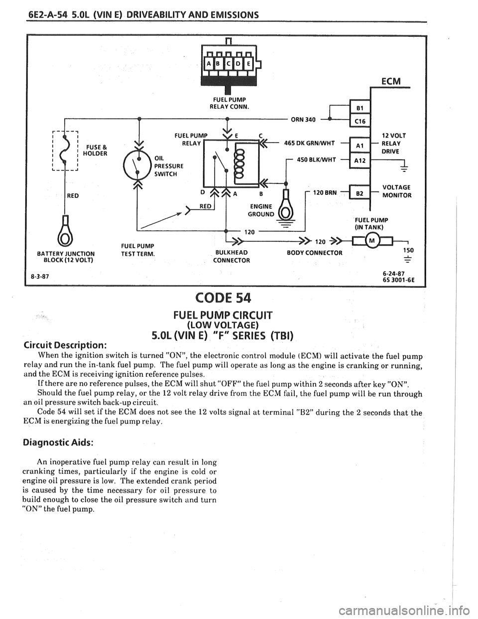
When the ignition switch is turned "ON", the electronic control module (ECM) will activate the fuel pump
relay and run the in-tank fuel pump. The fuel pump will operate as long as the engine is cranking or running,
and the ECM is receiving ignition reference pulses.
If there are no reference pulses, the ECM will shut
"OFF" the fuel pump within 2 seconds after key "ON".
Should the fuel pump relay, or the
12 volt relay drive from the ECM fail, the fuel pump will be run through
an oil pressure switch back-up circuit.
Code
54 will set if the ECM does not see the 12 volts signal at terminal "B2" during the 2 seconds that the
ECM is energizing the fuel pump relay.
Diagnostic Aids:
An inoperative fuel pump relay can result in long
cranking times, particularly if the engine is cold or
engine oil pressure is low. The extended crank period
is caused by the time necessary for oil pressure to
build enough to close the oil pressure switch and turn
"ON" the fuel pump.
Page 553 of 1825
6E2-8-6 5.OL (VIN E) DRIVEABILITY AND EMISSIONS
- MAP Sensor - Ignition "ON", engine stopped.
Compare MAP voltage with known good vehicle.
-
Voltage should be the same + 400 mV (.4 volts).
OR
Start and idle engine. Disconnect
sensor
electrical connector. If idle improves, substitute
a known good sensor and recheck.
- A/C refrigerant pressure too high. Check for
overcharge or faulty pressure switch.
- PCV valve for proper operation by placing finger
over inlet hole in valve end several times. Valve
should snap back. If not, replace valve.
Run a cylinder compression check See Section
" 6".
Inspect oxygen sensor for silicon contamination
from fuel, or use of improper RTV sealant. The
sensor will have a white, powdery coating, and
will result in a high but false signal voltage (rich
exhaust indication). The ECM will then reduce
the amount of fuel delivered to the engine,
causing a severe driveability problem.
EXCESSIVE EXHAUST EMISSIONS OR ODORS
Definition: Vehicle fails an emission test. Vehicle has excessive "rotten egg"
smell. Excessive odors do not necessarily indicate excessive emissions.
@ Perform "Diagnostic Circuit Check".
@ IF TEST SHOWS EXCESSIVE CO AND HC, (or
also has excessive odors)
@ Check items that will cause engine to run
RICH.
e Make sure engine is at normal operating
temperature.
o CHECK:
- Fuel pressure. See CHART A-7.
- Incorrect timing. See Vehicle Emission
Control Information label.
- Canister for fuel loading. See CHART C-3.
- PCV valve for being plugged, stuck or blocked
PCV hose or fuel in the crankcase.
- Spark plugs, plug wires, and ignition
components. See Section
"6D".
- Check for lead contamination of catalytic
converter (look for removal of fuel filler neck
restrictor).
- Check for properly installed fuel cap.
@ If the system is running rich, (block learn less
than
1181, refer to "Diagnostic Aids" on facing
page of Code
45.
o IF TEST SHOWS EXCESSIVE NOx:
@ Check items which cause car to run LEAN, or
to run too hot.
- EGR valve for not opening. See CHART C-7.
- Vacuum leaks. - Coolant system and coolant fan for proper
operation. See
CHART C-12.
- Remove carbon with top engine cleaner.
Follow instructions on can.
- Check ignition timing for excessive base
advance. See Emission Control Information
label.
@ If the system is running lean, (block learn greater
than
138) refer to "Diagnostic Aids" on facing
page of Code
44.
DIESELING, RUN-ON
Definition: Engine continues to run after key is turned "OFF", but runs very roughly.
Ifengine runs smoothly, check ignition switch and adjustment.
@ Check injector for leaking. Apply 12 volts to fuel Visually check injector and TBI assembly for fuel
pump test terminal to turn "ON" fuel pump and leakage.
pressurize fuel system.
BACKFIRE
Definition: Fuel ignites in intake manifold, making a loud popping noise.
@ CHECK: - For faulty spark plugs and/or plug wires or
- EGR operation for being open all the time. See
hoots.
CHART C-7. - Faulty A.I.R. check valve.
- Output voltage of ignition coil. @ Perform a compression check - look for sticking or
- For crossfire between spark plugs (distributor leaking valves.
cap, spark plug wires, and proper routing' of plug
- For proper valve timing.
wires).
- Broken or worn valve train parts.
- Engine timing - See Emission Control
Information label.
Page 561 of 1825
6EZ-C1-6 5.OL (VIN E) DRIVEABILITY AND EMISSIONS
A failure in the MAT sensor circuit should set a Code
23 or 25. The code charts also contain
a chart to check
for sensor resistance values relative to temperature.
MAP Sensor
A "ScanJ' tool reads manifold pressure and will
display either volts or
kPa of pressure.
Key "ONJ', engine stopped, (no vacuum), MAP will
read high voltage or pressure, while at idle
(highvacuum), MAP will read low voltage or pressure.
Likewise, on accel., MAP will read high and on decel.,
will read low.
A failure in the MAP sensor, or circuit, should
result in a Code 33 or 34.
Oxygen (02) Sensor
The "Scan" tool has several positions that will
indicate the state of the exhaust gases,
02 voltage,
integrator, and block learn. See "Scan" tool position
information in the Introduction of Section
"6E".
A problem in the O2 sensor circuit should set a
Code 13 (open circuit), Code
44 (lean 02 indication),
Code
45 (rich 02 indication). Refer to the applicable
chart, if any of these codes were stored in memory.
Throttle Position Sensor (TPS)
A "Scan" tool displays throttle position in volts.
The
5.OL should read under 1.25 volts, with throttle
closed and ignition on, or at idle. Voltage should
increase at a steady rate as throttle is moved toward
WOT. The ECM has the ability to Auto-Zero the TPS
voltage, if it is below about 1.25 volts. This means
that any voltage less than 1.25 volts volts will be
determined by the ECM to be
0% throttle. Some
"Scan" tools have the ability to read the percentage of
throttle angle and should read
0%, when the throttle
is closed.
A failure in the TPS circuit or TPS, should
set a Code 21 or 22.
Vehicle Speed Sensor (VSS)
A "Scan" tool reading should closely match with
speedometer reading, with drive wheels turning. A
failure in the VSS circuit should set a Code
24.
PIN Switch
A "Scan" tool should read "ON", when in park or
neutral and "OFF", when in drive. This reading may
vary with different makes of tools. Refer to CHART C-
IA for
PIN switch diagnosis.
Power steering Pressure Switch (POPS)
A Scan" tool should read "OFF" normally, and
"ON" with high pressure. This reading may vary with
different makes of tools. Refer to CHART
C-1E for
PSPS diagnosis.
NC Request Signal
If the low pressure switch is closed and AIC is
"ON", the "Scan" tool should indicate
A/C "ON".
Distributor Reference Signal
A "Scan" tool will read this signal and is displayed
in rpm. See Section
"C4", for more information on the
Ignition System
.
Knock Signal
A "Scan" tool will indicate when the ESC module
signals the ECM that knock is present. See Section
"C5" for further information on the ESC System.
ON-CAR SERVICE
ELECTRONIC CONTROL MODULE (ECM)
Service of the ECM should normally consist of
either replacement of the ECM or a PROM change.
If the diagnostic procedures call for the ECM to be
replaced, the engine calibrator (PROM) and ECM
should be checked first to see if they are the correct
parts. If they are, remove the PROM from the faulty
ECM and install it in the new service ECM. THE
SERVICE ECM
WILL NOT CONTAIN A PROM.
Trouble Code "51" indicates the PROM is installed
improperly or has malfunctioned. When Code "51" is
obtained, check the PROM installation for bent pins or
pins not fully seated in the socket. If the PROM is
installed correctly and Code
"51" still shows, replace
the PROM.
Important
When replacing the production ECM with a
service ECM (controller), it is important to
transfer the Broadcast code and production ECM
number to the service ECM label. Please do not
record on ECM cover. This will allow positive
identification of ECM parts throughout the service
life of the vehicle.