1988 PONTIAC FIERO key
[x] Cancel search: keyPage 171 of 1825
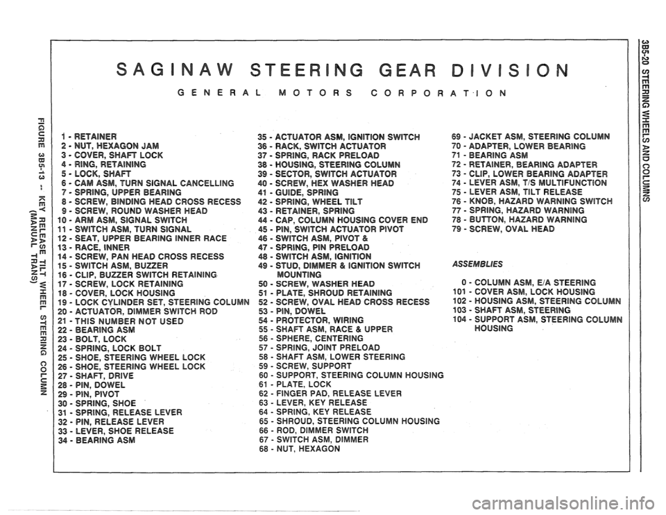
GENERAL MOTORS CORPORATION
1 - RETAINER
35 - ACTUATOR ASM, IGNITION SWITCH 69 - JACKET ASM, STEERING COLUMN
2 - NUT, HEXAGON JAM
36 - RACK, SWITCH ACTUATOR 70 - ADAF"TER, LOWER BEARING
3 - COVER, SHAn LOCK 37 - SPRING, RACK PRELOAD 71 - BEARING ASM
4
- RING, RETAINING 38 - HOUSING, STEERING COLUMN 72 - RETAINER, BEAR1NG ADAPTER
5 - LOCK, SHAn 39 - SECTOR, SWITCH ACTUATOR
73 - CLIP, LOWER BEARING ADAPTER
6
- CAM ASM, TURN SIGNAL CANCELLING 40 - SCREW, HEX WASHER HEAD 74 - LEVER ASM, T/S MULTlFUNCTBON
7 - SPRING, UPPER
BEARING
41 - GUIDE, SPRING 75 - LEVER ASM, TILT RELEASE
8
- SCREW, BINDING HEAD CROSS RECESS 42 - SPRING, WHEEL TILT 76 - KNOB, HAZARD WARNING SWlTCH
9 - SCREW, ROUND WASHER MEAD
43 - RETAINER, SPRING 77 - SPRING, HAZARD WARNING
10 - ARM ASM, SIGNAL SWITCH 44 - CAP, COLUMN HOUSING COVER END 78 - BUTBON, HAZARD WARNING
11 - SWITCH
ASM, TURN SIGNAL 45 - PIN, SWITCH ACTUATOR PIVOT 79 - SCREW, OVAL HEAD
12
- SEAT, UPPER BEARING INNER RACE 46 - SWITCH ASM, PIVOT &
13 - RACE, INNER 47 - SPRING, PIN PRELOAD
14
- SCREW, PAN HEAD CROSS RECESS 48 - SWITCH ASM, IGNITION
15 - SWITCH
ASM, BUZZER 49 - STUD, DlMMER & IGNITION SWITCH ASSEMBLIES
16 - CLIP, BUZZER SWITCH RETAINING MOUNTlNG
17 - SCREW,
LOCK RETAINING 50 - SCREW, WASHER HEAD 0 - COLUMN
ASM, EiA STEERING
18
- COVER, LOCK HOUSING 51 - PLATE, SHROUD RETAINING 101 - COVER ASM, LOCK HOUSING
19 - LOCK CYLINDER SET, STEERING COLUMN 52 - SCREW,
OVAL HEAD GROSS RECESS 102 - HOUSING
ASM, STEERlNG COLUMN
20
- ACTUATOR, DIMMER SWITCH ROD 53 - PIN, DOWEL 103 - SHAFT
ASM, STEERING
21 -THIS NUMBER NOT USED 54 - PROTECTOR, WIRING
104 - SUPPORT
ASM, STEERING COLUMN
22
- BEARING ASM 55 - SHAFT
ASM, RACE & UPPER HOUSING
23
- BOLT, LOCK 56 - SPHERE,
CENTERING
24
- SPRING, LOCK BOLT 57 - SPRING, JOINT PRELOAD
25
- SHOE, STEERING WHEEL LOCK 58 - SHAFT ASM, LOWER STEERING
26 - SHOE, STEERING WHEEL LOCK 59 - SCREW,
SUPPORT
27
- SHAFT, DRIVE 60 - SUPPORT, STEERlNG COLUMN HOUSING
28
- PIN, DOWEL 61 - PLATE,
LOCK
29
- PIN, PIVOT 62 - FINGER PAD, RELEASE LEVER
30
- SPRING, SHOE 63 - LEVER, KEY RELEASE
31
- SPRING, RELEASE LEVER 64 - SPRING,
KEY RELEASE
32 - PIN, RELEASE LEVER 65 - SHROUD, STEERING COLUMN HOUSING
33
- LEVER, SHOE RELEASE 66 - ROD, DIMMER SWlTCH
34 - BEARING ASM 67 - SWITCH ASM, DlMrVlER
68 - NUT,
HEXAGON
Page 172 of 1825
STEERING WHEELS AND COLUMNS 385-21
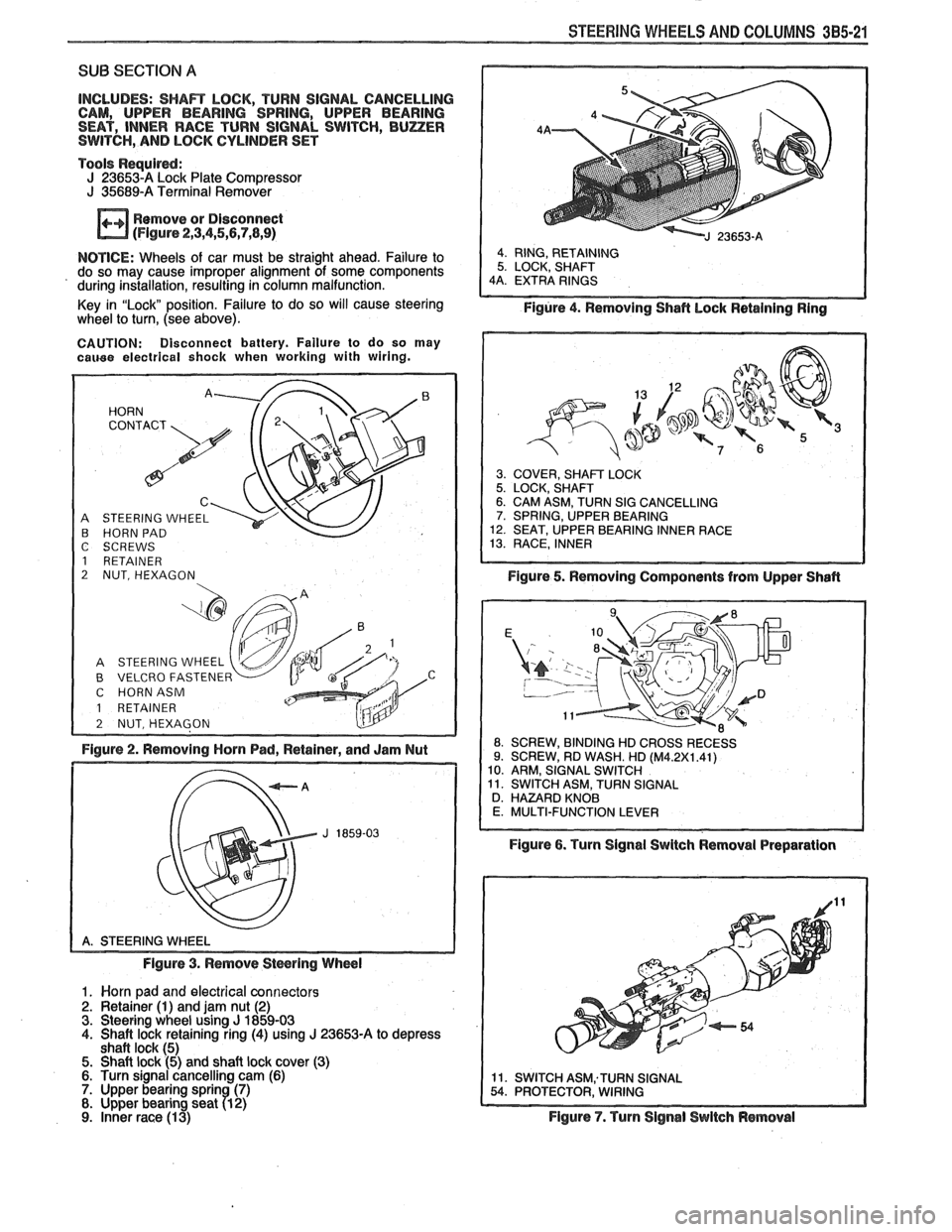
SUB SECTION A
INCLUDES: SHAR LOCK, TURN SIGNAL CANCELLING
CAM, UPPER BEARING SPRING, UPPER BEARING
SEAT, INNER RACE TURN SIGNAL SWITCH,
BUZER SWITCH, AND LOCK CYLINDER SET
Tools
Requird: J 236534 Lock Plate Compressor J 35689-A Terminal Remover
Remove or Disconnect
(Flgure 2,3,4,5,5,7,8,9)
NOTICE: Wheels of car must be straight ahead. Failure to
do so may cause improper alignment of some components
' during installation, resulting in column malfunction.
Key in "Lock" position. Failure to do so will cause steering
wheel
to turn, (see above).
CAUTION: Disconnect battery. Failure to do so may cauee electrical shock when working with wiring.
A STEERING WHEEL B HORN PAD
C SCREWS
1 RETAINER
2 NUT, HEXAGON
B VELCRO FASTENER C HORNASM
1 RETAINER
Figure 2. Removing Horn Pad, Retainer, and Jam Nut
Figure 3. Remove
Stwring Wheel
1. Worn pad and electrical connectors 2. Retainer (1) and jam nut (2) 3. Steering wheel using J 1859-03 4. Shaft lock retaining ring (4) using J 23653-A to depress
shaft lock (5) 5. Shaft lock (5) and shaft lock cover (3) 6. Turn signal cancelling cam (6) 7. Upper bearing sprin (7) 8. Upper bearing seat 71 2)
9. inner race (1 3)
Figure 4. Removing Shafl hock Retaining Ring
3. COVER, SHAFT LOCK 5. LOCK, SHAFT 6. CAM ASM, TURN SIG CANCELLING 7. SPRING, UPPER BEARING 12. SEAT, UPPER BEARING INNER RACE 13. RACE, INNER
Figure 5. Removing Components from Upper Shafl
ROSSRECESS
Figure 6. Turn Signal Swltch Removal Preparation
Figure
7. Turn Signal Switch Removal
Page 173 of 1825
385-22 STEERING WHEELS AND COLUMNS
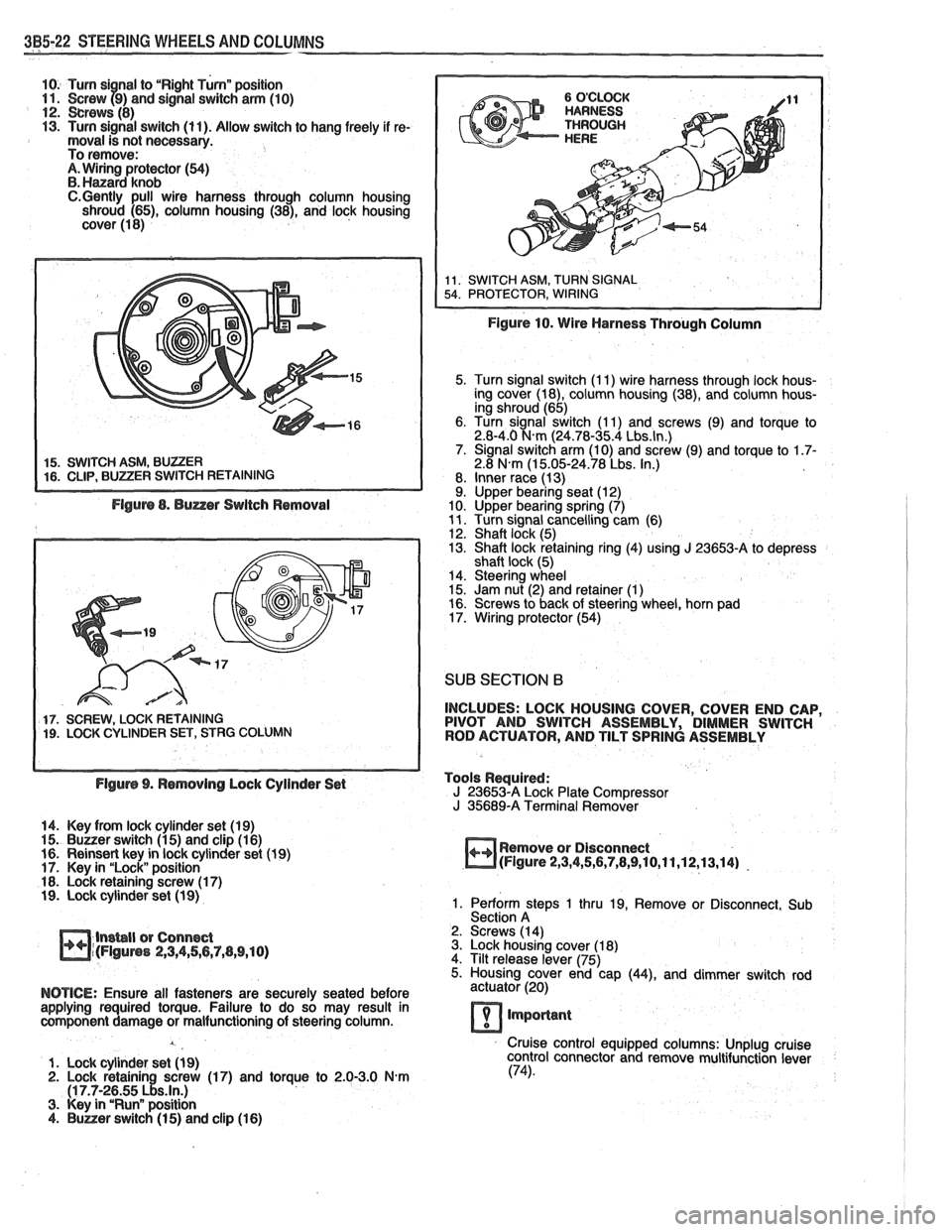
10. Turn si nal to "Right Turnn position 11. Screw f9) and signal switch arm (10) 12. crews (8) 13. Turn signal switch (11). Allow switch to hang freely if re- moval is not necessary.
To remove:
A. Wiring protector (54) B. Hanard knob C.Gently pull wire harness through column housing
shroud (65), column housing (38), and lock housing
cover (1 8)
5. Turn signal switch (I 1) wire harness through lock hous-
ing cover (18), column housing (38), and column hous-
ing shroud (65)
6. Turn signal switch (1 1) and screws (9) and torque to
2.8-4.0
N.m (24.78-35.4 Lbs.ln.) 7. Signal switch arm (10) and screw (9) and torque to 1.7- 2.8 N.m (1 5.05-24.78 Lbs. In.)
8. Inner race (13)
9. Upper bearing seat (12)
10. Upper bearing spring (7)
11. Turn signal cancelling cam (6)
12. Shaft lock (5)
13. Shaft lock retaining ring (4) using J 23653-A to depress
shaft lock (5)
14. Steering wheel
15. Jam nut (2) and retainer
(1) 16. Screws to back of steering wheel, horn pad
17. Wiring protector (54)
SUB SECTION 6
17. SCREW, LOCK RETAINING INCLUDES:
LOCK HOUSING COVER, COVER END CAP, 19. LOCK CYLINDER SET, STRG COLUMN PIVOT
AND SWITCH ASSEMBLY, DIMMER SWITCH
ROD ACTUATOR, AND TILT SPRING ASSEMBLY
Flgurs 9. Rsmovlng Lock Cylinder Set Tools
Required:
J 23653-A Lock Plate Compressor
J 35689-A Terminal Remover
14. Key from lock cylinder set (19)
15.
Buuer switch (1 5) and clip (1 6)
16. Reinsert key in lock cylinder set (1 9) Remove
or Disconnect
17. Key in "Lock" position
m(Flgure 2,3,4,5,6,7,8,9,10,11,12,13,14) -
18. Lock retaining screw (1 7) 19. Lock cylinder set (1 9) 1. Perform steps 1 thru 19, Remove or Disconnect, Sub
Section A
lnsbll or Connect 2.
Screws (14)
m~(FIguns 2,3,4,56,7,(1,9,10) 3. Lock housing cover (1 8)
4. Tilt release lever (75)
5. Housing cover end cap
(44), and dimmer switch rod
NOTICE: Ensure all fasteners are securely seated before actuator (20)
applying required torque. Failure to do so may result in
component damage or malfunctioning of steering column.
lmporlant
Cruise control equipped columns: Unplug cruise
1. Lock cylinder set
(1 9) control
connector and remove multifunction lever 2. Lock retainin screw (17) and torque to 2.0-3.0 N-m (74).
(1 7.7-2~55 ~!s.ln.) 3. Key in "Runn position 4. Buner switch (1 5) and clip (1 6)
Page 177 of 1825
3B5-26 STEERING WHEELS AND COLUMNS
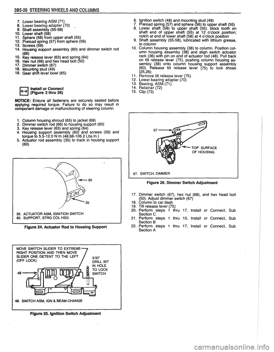
7. Lower bearing ASM (71)
8. Lower bearing adapter (70) - 9. Shaft assembly (55-58)
10. Lower shaft (58)
11. Sphere (56) from upper shaft (55) 12. Preload spring (57) from sphere (56)
13. Screws (59)
14. Housing support assembly (60) and dimmer switch rod
If%
15. i<'si release lever (63) and spring (64) 16. Hex nut (68) and hex head bolt (50)
17. Dimmer switch (67)
18. Mounting stud (49)
19. Gear shift lever bowl (65) Ignition switch (48)
and
mountin stud (49)
Preload spring (57) and sphere 156) to upper shaft (55)
Lower shaft (58) to upper shaft (55). block tooth on
shaft end of upper shaft (55) at 12 o'clock position;
notch at end of lower shaft (58) at 4 o'clock position
Shaft assembly
(55-58), lubricated with lithium grease,
to column
Column housing assembly (38) to column. Position col-
umn housing
assemby (38) and align switch actuator
rack (36) with pin on end of actuator rod (48). Pull back
on tilt release lever
(75), pushing column housing as-
sembly (38) onto column housing support assembly
(60). Release tilt release lever (75) to lock shoes
(2526) Remove tilt release lever 175) 12. Lower bearing adapter (70) '
13. Bearing, ASM (71)
In~bll or Connect 14. Retainer (72)
(Figure 2 thru 26) 15. Clip (73)
WTICE: Ensure all fasteners are securely seated before aaplying required torque. Failure to do so may result in component damage or malfunctioning of steering column.
1. Column housing shroud (65) to jacket (69)
2. Dimmer switch rod (66) to housing support (60)
3. Key release lever (63) and spring (64)
4. Housing support assembly (60) and screws (59) and
torque to
5.5-12.0 N.m (48.68-106.2 Lbs.ln.) 5. Actuator rod assembly (35) to track in housing support
(60)
35. ACTUATOR ASM, IGNITION SWITCH 60. SUPPORT, STRG COL HSG TOP
SURFACE
OF HOUSING
Figure 26. Dimmer Switch Adjustment
17. Dimmer switch (67), hex nut (68), and hex head bolt
(50). Adjust dimmer switch (67)
18. Column to car dash
19. Tilt release lever (75)
20. Perform steps 1 thru 17, Install or Connect, Sub
Section C
21. Perform steps 1 thru 10, Install or Connect, Sub
Section B
Figure 24. Actuator Rod to Housing Support 22. Perform steps 1 thru 17, Install or Connect, Sub
Section A
48. SWITCH ASM, IGN & BEAM CHANGE
Flgure 25. lgnitlon Switch Adjustment
Page 180 of 1825
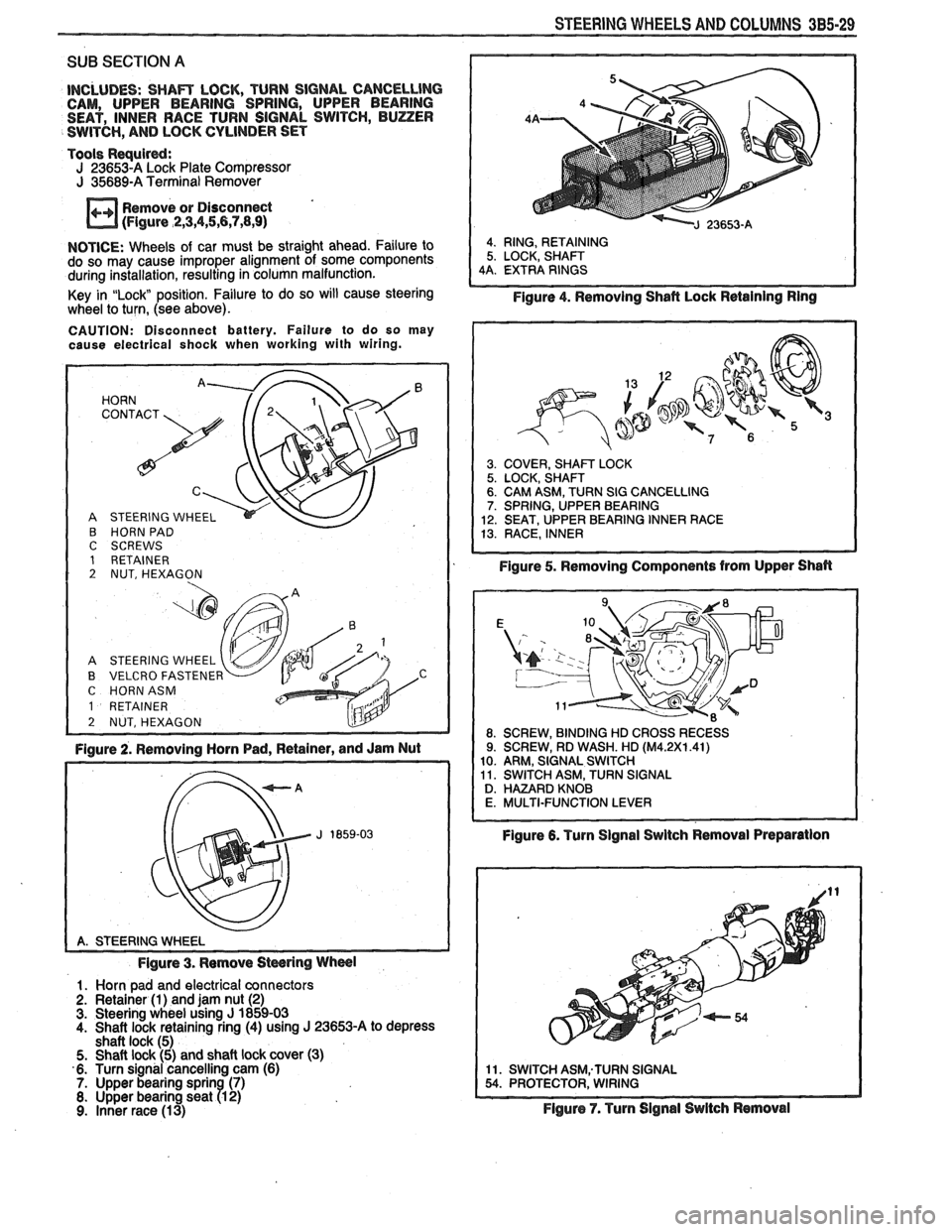
STEERING WHEELS AND COLUMNS 3B5-29
SUB SECTION A
INCLUDES: SHAm LOCK, TURN SIGNAL CANCELLlNG CAM, UPPER BEARING SPRING, UPPER BEARING
SEAT, INNER RACE TURN SIGNAL SWITCH, BUZZER
SWITCH,
AND LOCK CYLINDER SET
Tools
Requird: J 23653-A Lock Plate Compressor J 35689-A Terminal Remover
Remove or Disconnect
(Figure
,2,3,4,5,6,7,8,9)
NOTICE: Wheels of car must be straight ahead. Failure to
do so may cause improper alignment of some components
during installation, resulting in column malfunction.
Key in
"Lock position. Failure to do so will cause steering
wheel to turn, (see above).
CAUTION: Disconnect battery. Failure to do so may
cause electrical shock when working with wiring.
HORN '. 72' CONTACT
A STEERING WHEEL
B HORN PAD C SCREWS 1 RETAINER 2 NUT, HEXAGON
A STEERING WHEEL
B VELCRO FASTENER C HORNASM
1 RETAINER
2 NUT, HEXAGON L!lY -
Figure 2. Removing Horn Pad, Retainer, and Jam Nut
Figure 3. Remove
Stwring Wheel
1. Horn pad and electrical connectors
2. Retainer (1) and jam nut (2) 3. Steering wheel using J 1859-03
4. Shaft lock retaining ring (4) using J 23653-A to depress
shaft lock (5)
5. Shaft lock (5) and shaft lock cover (3)
6. Turn signal cancelling cam (6)
7. Upper bearing sprin (7) 8. Upper bearing seat R 2) 9. Inner race (13)
4. RING, RETAINING
5. LOCK, SHAFT
4A. EXTRA RINGS
Figure 4. Removing Shafl Lock Retaining Ring
3. COVER, SHAm LOCK 5. LOCK, SHAFT 6. CAM ASM, TURN SIG CANCELLING 7. SPRING, UPPER BEARING
12. SEAT, UPPER BEARING INNER RACE
13. RACE, INNER
Figure 5. Removing Components from Upper Shan
Figure 6. Turn Signal Swltch Removal Preparation
11. SWITCH ASM;TURN SIGNAL 54. PROTECTOR, WIRING
Flgure 7. Turn Signal Switch Removal
Page 181 of 1825
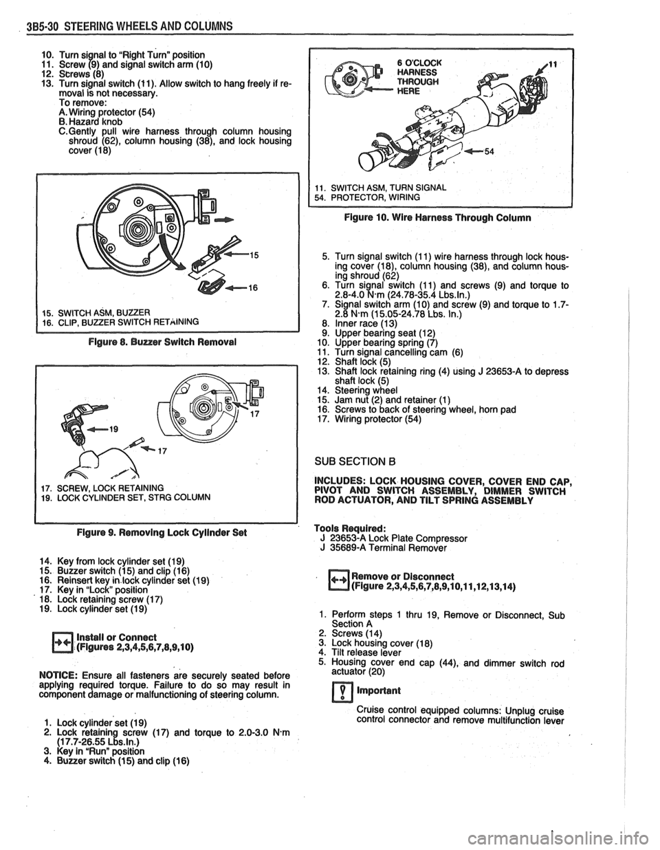
385-30 STEERING WHEELS AND COLUMNS
10. Turn si nal to "Right Turn" position
11. Screw 79) and signal switch arm (10)
12. Screws (8)
13. Turn signal switch (11). Allow switch to hang freely if re-
moval is not necessary.
To remove:
A. Wiring protector (54)
B. Hazard knob
C.Gently pull wire harness through column housing
shroud (62), column housing (38), and lock housing
cover (1 8)
Figure 8. Buzzer Switch Removal
17. SCREW, LOCK RETAINING 19. LOCK CYLINDER SET, STRG COLUMN
Figure 10. Wire Harness Through Column
5. Turn signal switch (1 1) wire harness through lock hous-
ing cover
(la), column housing (38), and column hous-
ing shroud (62)
6. Turn
sianal switch (1 1) and screws (9) and torque to 2.8-4.0 %km (24.78-35.4 Lbs.ln.) 7. Signal switch arm (10) and screw (9) and torque to 1.7- 2.8 N-m (1 5.05-24.78 Lbs. In.)
8. Inner race (1 3) 9. Upper bearing seat (1 2)
10. Upper bearing spring (7)
11. Turn signal cancelling cam (6)
12. Shaft lock (5)
13. Shaft lock retaining ring (4) using
J 23653-A to depress
shaft lock (5)
14. Steering wheel
15. Jam nut (2) and retainer (1
) 16. Screws to back of steering wheel, horn pad
17. Wiring protector (54)
SUB SECTION B
INCLUDES: LOCK HOUSING COVER, COVER END CAP,
PIVOT AND SWITCH ASSEMBLY, DIMMER SWITCH
ROD ACTUATOR, AND TILT SPRING ASSEMBLY
Figure 9. Removing Lock Cyilnder Set Tools
Rwuired: J 23653-A Lock
Plate Compressor J 35689-A Terminal Remover
14. Key from lock cylinder set (19)
15. Buzzer switch (1 5) and clip (1 6)
16. Reinsert key
in.lock cylinder set (19)
17. Key in "Lock" position
18. Lock retaining screw (1 7)
19. Lock cylinder set (1 9)
Install or Connect
(Figures
2,3,4,5,6,7,8,9,10)
Remove or Dlsconnect (Figure 2,3,4,5,6,7,8,9,10,11,12,13,14)
1. Perform steps 1 thru 19, Remove or Disconnect, Sub
Section A
2. Screws (1 4)
3. Lock housing cover (1 8)
4. Tilt release lever
5. Housing cover end cap
(44), and dimmer switch rod
NOTICE: Ensure all fasteners are securely seated before actuator
(20)
applying required torque. Failure to do so may result in
component damage or malfunctioning of steering column.
7 important
Cruise control equipped columns: Unplug cruise
1. Lock cylinder set (1 9) control
connector and remove multifunction lever
2. Lock retaining screw (17) and torque to 2.0-3.0 N.m (1 7.7-26.55 Lbs.ln.) 3. Key in "Run" position
4. Buuer switch (1 5) and clip (16)
Page 205 of 1825
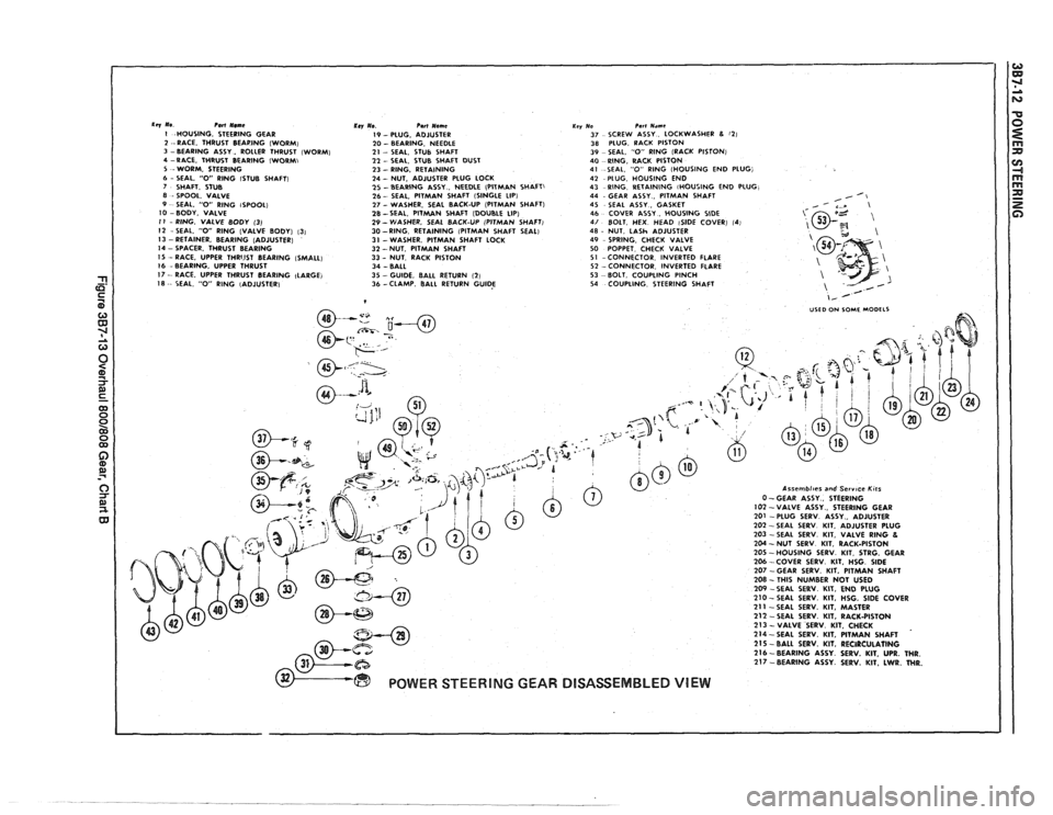
1 -HOUSING. STEERING GEAR 2 --RACE. THRUST BEAPING (WORM) 3 -BEARING ASSY . ROLLER THRUST (WORM) 4 -RACE. THRUST BEARING IWORMI 5 ~-WORM. STEERING 6 - SEAL. "0" RlNG lSTUB SHAFTI 7 SHAFT. STUB 8 - SPOOL. VALVE 9 SEAL. "0" RlNG ISPOOL) I0 - BODY. VALVE I I - RING. VALVE 80DY (3) 12 -SEAL. "0" RlNG (VALVE BODY) (31 I3 - RETAINER. BEARING (ADJUSTER)
I4 - SPACER. THRUST BEARING
IS - RACE. UPPER THRIJST BEARING (SMALL) I6 -BEARING. UPPER THRUST
Ti I7 - RACE. UPPER THRUST BEARING (LARGE)
5- I8 -- SEAL, "0" RlNG IADIUSTERI C
Krv Ue Pert Nemc I9 - PLUG. ADJUSTER 20 - BEARING. NEEDLE 21 -- SEAL. STUB SHAFT 21 - SEAL. STUB SHAFT DUST 23 - RING. RETAINING 24 - NUT. ADJUSTER PLUG LOCK 25 - BEARiNG ASSY . NEEDLE (PITMAN SHAFT) 26 - SEAL. PITMAN SHAFT (SINGLE LIP) 27 - WASHER, SEAL BACK-UP (PITMAN SHAFT)
28-SEAL. PITMAN SHAFT (DOUBLE LIP) 29 - VtASHER. SEAL BACK-UP (PITMAN SHAFT) 30 -RING RETAINING (PITMAN SHAFT SEAL)
31 -WASHER. PITMAN SHAFT LOCK 32 -NUT. PITMAN SHAFT 33 - NUT RACK PISTON 34 - BALL 35 -GUIDE. BALL RETURN (21 36 -CLAMP BALL RETURN GUIDE
Key No Pan Nrme 37 SCREW ASSY LOCKWASHER 8 (21 38 PLUG RACK PISTON 39 SEAL 0 RING (RACK PISTON) 40 RlNG RACK PISTON 41 SEAL 0 RlNG (HOUSING END PLUG, 42 PLUG HOUSING END 43 RING RETAINING iHOULlNG END PLUG 44 GEAR ASSY PITMAN SHAFT
45 SEAL ASSY GASKET
46 COVER ASSY HOUSING SlDE 4/ BOLT HEX HEAD ISIDE COVER) 14 48 NUT LASh ADJUSTER 49 SPRING CHECK VALVE 50 POPPET CHECK VALVE 51 -CONNECTOR INVERTED FLARE 52 -CONNECTOR INVERTED FLARE 53 BOLT COUPLING PINCH 54 COUPLING STEERING SHAFT
Page 310 of 1825
BRAKES 5-17
maintaining proper wheel balance, brake drums should be
checked for balance. Brake drums may be checked for
balance on most off-the-car balancers.
COMBINATION VALVE
Testing Combination Valve Electrical Circuit
When removing the electrical wire connector from the
pressure differential switch, squeeze the
eliptical shaped
plastic locking ring and pull up. This will move the locking
tangs away from the switch. Pliers can be used to help
remove the connector.
1. Disconnect wire from switch terminal and use a
jumper to connect wire to a good ground.
2. Turn ignition key to "ON." The warning lamp should
light. If lamp does not light, bulb is burned out or
electrical circuit is faulty. Replace bulb or repair elec-
trical circuit as necessary.
3. When warning lamp lights, turn off ignition switch.
Disconnect jumper and connect wire to switch termi-
nal.
Testing Combination Valve Warning Lamp Switch
1. Attach a bleeder hose to a rear brake bleed screw and
immerse the other end of the hose in a container
partially filled with clean brake fluid. Be sure master
cylinder reservoirs are full.
2. Turn ignition switch to "ON." Open bleeder screw
while an assistant applies moderate pressure to the
brake pedal. Warning lamp should light. Close
bleeder screw before assistant releases brake pedal.
Apply brake pedal with moderate-to-heavy pressure.
Lamp should go out.
3. Attach the bleeder hose to a front brake bleeder
screw and repeat steps
1 and 2. Warning lamp action
should be the same as in step
2. Turn off ignition
switch.
4. If warning lamp does not light during steps 2 and 3,
but does light when a jumper is connected to ground,
the warning lamp switch portion of the combination
valve is faulty. Do not disassemble the combination
valve.
If any portion of the combination valve is faulty,
it must be replaced with a new combination valve.
Combination Valve Replacement
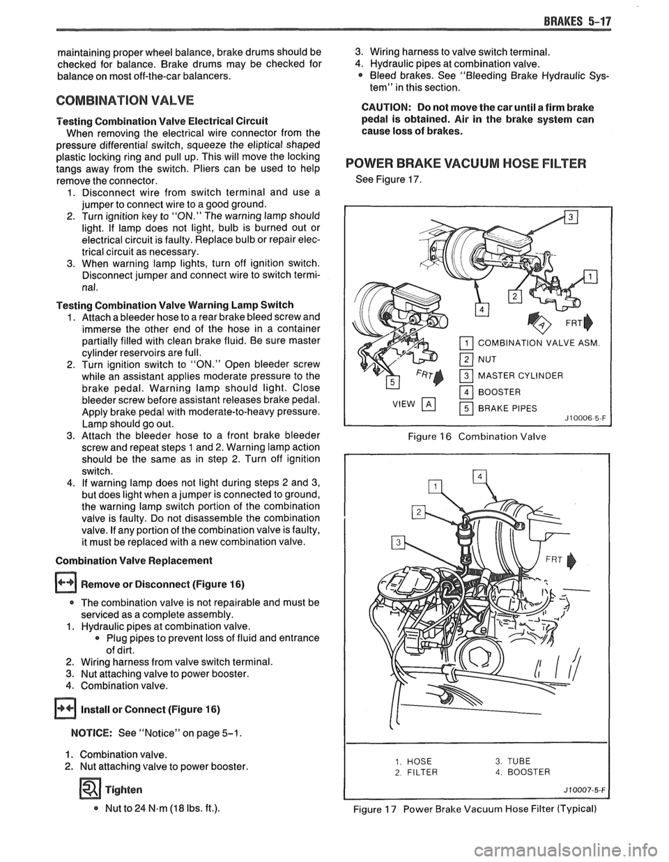
Remove or Disconnect (Figure
16)
r The combination valve is not repairable and must be
serviced as a complete assembly.
1. Hydraulic pipes at combination valve.
Plug pipes to prevent loss of fluid and entrance
of dirt.
2. Wiring harness from valve switch terminal.
3. Nut attaching valve to power booster.
4. Combination valve.
@ Install or Connect (Figure 16)
NOTICE: See "Notice" on page 5-1.
1. Combination valve.
2. Nut attaching valve to power booster.
Tighten
* Nut to 24 N.m (18 Ibs. ft.).
3. Wiring harness to valve switch terminal.
4. Hydraulic pipes at combination valve. * Bleed brakes. See "Bleeding Brake Hydraulic Sys-
tem" in this section.
CAUTION: Do not move the car until a firm brake
pedal is obtained. Air in the brake system can
cause loss of brakes.
POWER BRAKE VACUUM HOSE FILTER
See Figure 17.
COMBINATION VALVE ASM.
MASTER CYLINDER BRAKE PIPES
Figure 16 Combination Valve
2 FILTER 4. BOOSTER
Figure 17 Power Brake Vacuum Hose Filter (Typical)