1988 PONTIAC FIERO key
[x] Cancel search: keyPage 113 of 1825
866 CHASSIS SHEET METAL
PROPER IDENTIFICATION AND CDAlrUmNG
OF INTERIOR PWSTIC TRlM
Interior plastic trim parts are normally supplied
in only one color. It is necessary to paint most parts.
Most vinyl headlinings and soft vinyl seat cushion and
hack cover assemblies are furnished in colors.
Instructions on how to identify each paintable
plastic part, and how to apply the available paint
materials are as follows:
Paintable plastic trim components, as used on
General Motors interiors, can be divided into three
general types:
@ Polypropylene Plastic
@ ABS Plastic
@ Vinyl Plastic
Excluding the soft vinyl seat cushion and seat
back trim cover assemblies, the plastic used most
widely on the interior of bodies is "POLYPROPYL-
ENE" and, as noted later, requires special refinishing
materials and procedures. Therefore, it is important
for a painter to be able to identify each plastic in order
to paint it satisfactorily. The purpose of the following
tests is to determine the identity of a given plastic so
that the proper paint procedure and refinishing mate-
rials will be used.
TEST PROCEDURE
Polypropylene, ABS or Vinyl Plastic
From a hidden backside portion of the part,
remove a sliver of plastic with a sharp blade.
Holding the sliver with needle-nose pliers, put it
to a flame and observe whether or not any
smoke is given off when burning.
ABS PLASTIC will give off a HEAVY BLACK
SMOKE, and POLYPROPYLENE will burn
clean.
However, if a sliver gives off OTHER THAN
HEAVY BLACK SMOKE, it is either DIRTY
POLYPROPYLENE OR IS VINYL. To deter-
mine which it is, the following burn test should
be made with the hot tip of a clean copper wire.
Heat the tip of the copper wire to a "red-glow"
with a propane (gas) torch.
Touch the heated wire to a hidden portion of the
plastic in question, to get some of the plastic on
the wire.
Return the wire, with its
now plastic-coated tip,
to the flame and observe for flame color.
If the flame given off from the wire is of the
GREEN-TURQUOISE-BLUE RANGE, then
the PLASTIC IS VINYL. (Any other color
flame would indicate the material is dirty poly-
propylene.
)
PAINWING lNTERiOR PWSTIC PARTS
Before painting, always check the body number
plate of the car for the
correct trim code color number
for that model year. The body number plate is located
on the upper horizontal surface of the shroud. Interior
color is color keyed to this "Trim Combination Num-
ber" (TR) on the body plate. Each paint supplier pro-
vides an interior color chart which identifies their
stock number, color name, gloss factor and trim com-
bination number for each "conventional" interior
color. Charts listing "vinyl" interior colors are also
provided.
"CONVENTIONAL" interior acrylic colors are
designed for use only on hard trim parts, such as:
1. Steel parts (primer or sealer required on new
service parts).
2. Hard POLYPROPYLENE plastic ("Special
Primer" required
- See GM Parts Catalog).
3. Hard ABS plastic (NO primer necessary).
"VINYL" interior colors are designed for soft
and/or flexible trim parts, such as instrument panel
cover pad assemblies, upper door trim pad assem-
blies, molded headlining panels, head rests and assist
handles. These colors require a final top coat of clear
vinyl spray, with instrument panel pads requiring a
"nonglare" clear final top coat. Other trim parts
require a degree of gloss to match similar adjacent
parts.
POLYPROPYLENE PUSTIC PARTS
The system for painting polypropylene parts
involves the use of a special primer. It is essential that
the service part be first primed with a coating of spe-
cial POLYPROPYLENE PRIMER (Detroit
Autobody
#PP-2250, or equivalent) according to factory recom-
mendations on the can. Because the primer acts as a
bonding agent between the plastic and acrylic lacquer, failure to use it will result in color coat "lifting"
and/or
"peeling" problems. After priming, the part can be
color coated with conventional interior acrylic
lacquer,
PROCEDURE
1. Wash part thoroughly with a cleaning solvent ("Acryli-Clean," "Prep-Sol," or equivalent) that
will not leave any greasy film.
2. Apply a thin, wet coat of the special polypropyl-
ene primer according to label directions on can.
Wetness of primer is best determined by observ-
ing gloss reflection of spray application in ade-
quate lighting. Be sure primer application
includes all edges. Allow
the primer to flash dry
ONE (1) MINUTE MINIMUM and TEN (10)
MINUTES MAXIMUM. (If the flash period
before color coating should extend beyond ten
minutes, the primer MUST be reapplied to
avoid previously mentioned adhesion
problems
.)
Page 126 of 1825
STEERING, SUSPENSION, f IRES AND WHEELS DIAGNOSIS 3.1
SECVION 3
STEER NG, SUSPENS
WHEELS
AGNOS
CONTENTS
........................................... General Information 3- 1 ............................................ General Diagnosis 3- 1
Power Recirculating Ball .................................. 3-3
................. Steering Linkage ........................ .. 3-3
Power Steering Pump ................... ... ............ 3-4
Steering Column
Lock System
........................... ... ................ 3-4
Column ............................................................ 3-5
........................................ Turn Signal Switch 3-6
Ignition Switch .............................................. 3-7
Key Reminder .............................................. 3-7
Dimmer Switch .................... ... ................ 3-10
Pivot and Switch Assembly ............................ 3-10
Steering Gear and Pump Leaks .......................... 3- 10
Seal Replacement Recommendations ................. 3- 10
Power Steering System Test Procedure .............. 3-12
................ Strut Dampener and Shock Absorber 3- 12
Tires ........................ .. ..................................... 3- 13
Vibrations .......................... .............. .................... 3- 14
.......................... Tapered Roller Bearings .. .... 3- 14
Trim Height .............................................. 3-14
GENERAL INFORMATION Abnormal or Excessive Tire Wear
Since the problems in steering, suspension, tires
and wheels involve several systems, they must all be
considered when diagnosing a complaint. To avoid
e Front-wheel or rear-wheel alignment
using the wrong symptom, always road test the car
o Sagging or broken springs
first. Proceed with the following preliminary checks
Tire out of balance and correct any substandard conditions which are worn strut dampener or shock absorber found. o Hard driving
--
e Tires for wrong pressure and uneven wear
o Joints from the column to the steering gear for
loose connectors or wear
o Front and rear suspension, and the steering gear
or linkage for loose or damaged parts
Out-of-round or out-of-balance tires, bent wheels,
and loose and/or rough wheel bearings
@ Power steering system for leaks. Also check the
power steering fluid level and the pump drive belt
tension
GENERAL DIAGNOSIS
Car Pulls (Leads)
Inspect
Mismatched or uneven tires
Broken or sagging springs
Radial tire lateral force
Front-wheel or rear-wheel alignment
o Steering gear valve off center (unbalanced)
e Front brakes dragging
a Overloaded car
e Not rotating tires
Scuffed Tires
o Toe incorrect
e Excessive speed on turns
o Suspension arm bent or twisted
Wheel Tramp
Inspect
o Blister or bump on tire
o Improper strut dampener or shock absorber
action
Shimmy, Shake or Vibration
inspect
e Tire or wheel out of balance
e Worn wheel bearings
a Worn tie rod ends
o Worn lower ball joints
Page 130 of 1825
STEERING. SUSPENSION. TIRES AND WHEELS DIAGNOSIS 3-5
High Lock Effort
rn lnspect
e Lock cylinder damaged
e Ignition switch damaged
o Rack preload spring broken or deformed
e Burrs on sector, rack, housing, support or
actuator rod coupling
,
e Bent sector shaft
e Damaged rack
e Extreme misalignment of' housing to cover
e Distorted coupling slot in rack
e Bent actuator rod
e Ignition switch mounting bracket bent
e Actuator rod restricted
e Improper shift linkage adjustment
Will Stick In "Start"
rn lnspect
e Actuator rod deformed
e Check items under "High Lock Effort"
Key Cannot Be Removed in "Off-Lock"
rn lnspect
e Ignition switch is not set correctly
e Damaged lock cylinder
e Linkage mis-adjusted
Lock Cylinder Can Be Removed
Inspect
e Lock cylinder retaining screw missing
High Effort In Lock Cylinder Between "Off" and
"Off-Lock"
lnspect
o Distorted rack
Lock Bolt Hits Shaft Lock In "Off" Position and
"Park"
lnspect
e Ignition switch is not set correctly
COLUMN
Noise In Column
Inspect
e Joints from the column to the steering gear 1
e Column not correctly aligned
e Horn contact ring not lubricated
e Lack of grease on bearings
o Loose sight shields
o Lower or upper steering shaft bearing worn or
broken
e Shaft lock snap ring not seated
o Spherical joint not lubricated
High Steering Shaft Effort
e Column assembly misaligned
e Improperly installed or deformed dust seal
e Damaged upper or lower bearing
e Flash on I.D. of shift tube
e Tight intermediate steering shaft universal joint
High Shift Effort (Automatic with Column Shift)
rn lnspect
e Column not aligned correctly in car
e Wave washer with burrs
e Improperly installed dust seal
o Lack of grease on seal or bearing
e Improper screws used for ignition switch
e Burr on upper or lower end of shift tube
e Lower bowl bearing not assembled correctly
Improper Shifting (Automatic with Column
Shift)
rn lnspect
e Sheared shift tube joint or lower shift lever weld
e Improper or loose linkage adjustment
e 1,oose shift lever
e Improper gate plate
Lash In Steering Column
lnspect
e 1.P.-to-column upper and lower bracket
nlounting bolts loose
e Broken weld nuts on jacket
e I.P. upper bracket capsule sheared
e Loose shoes in housing
e Loose tilt head pivot pins
e Loose shoe lock pin in support
e Loose support screws
e Column upper and lower bracket-to-jacket bolts
loose
e Loose lower bracket-to-adapter and bearing
assembly mounting screws
e Loose 1.P.-to-jacket mounting bolts
Housing Scraping On Bowl
rn Inspect
e Bowl bent or not concentric with hub
e Cover and housing end cap not properly installed
Page 132 of 1825
STEERING, SUSPENSION, TIRES AND WHEELS DIAGNOSIS 3-7
e To determine if turn signal switch is inoperative,
substitute new turn signal switch into circuit and
operate switch by hand.
If the car's lights operate
normally, turn signal switch is inoperative.
Front Or Rear Turn Signal Lights Not Flashing
Inspect
s Burned-out or damaged turn signal bulb
e High resistance conection to ground at bulb
socket
s Loose chassis-to-column connector. Disconnect
column-to-chassis connector and connect new
turn signal switch into system and operate switch
by hand.
A. If turn signal lights are now on and flashing,
turn signal switch is inoperative.
B. If car lights do not operate, refer to Section
8A
for electrical diagnosis.
Turn Indicator Panel Lights
Inspect
Burned out bulbs or opens, grounds in the wiring
harness from the front turn signal bulb socket to the
indicator lights. Refer to Section
8A for electrical
diagnosis.
Stop Light Mot On When Turn Indicated
Inspect
s Loose column-to-chassis connection
e Disconnect the column-to-chassis connector and
connect the new turn signal switch into the
system and operate the switch by hand.
A. If the brake lights work when the switch is
in the turn position, the turn signal switch
is inoperative.
B. If the brake lights do not work, refer to Section
8A for electrical diagnosis.
Turn Signal Lights Flash Very Slowly
e Loose chassis-to-column connection
a Disconnect the column-to-chassis connector and
connect a new turn signal switch into the system
and operate the switch by hand.
A. If the lights flash at a normal rate, the turn
signal switch is inoperative.
B. If the Lights still flash very slowly, refer to
Section
8A for electrical diagnosis.
Hazard Signal Lights Will Not Flash - Turn
Signal Functions Normally
~"SPBC~
a Blown fuse
Inoperative hazard warning flasher
e Loose chassis-to-column connection
s Disconnect the column-to-chassis connector and
connect a new turn signal switch into the system,
then press in the hazard warning button and
watch the hazard warning lights.
A. If the lights now work normally, the turn
signal switch is inoperative.
B. If the lights do not flash, check the wiring
harness. Refer to Section
8A for electrical
diagnosis.
IGNITION SWITCH
Electrical System Will Not Function
Damaged ign~rion switch
e Ignition switch not adjusted properly
e Loose connector at the ignition switch
Switch Will Not Turn
Inspect
Damaged ignition switch
Switch Cannot Be Set Correctly
Inspect
Switch actuator rod deformed
e Sector to rack engaged in wrong tooth
KEY REMINDER
Figs. 1 through 11 ,
Weminder Continues To Operate With Key Out,
But Stops When Driver's Door Is Closed
e Chips, foreign material in lock cylinder bore
Sticky lock cylinder actuator tip
Damaged or broken reminder switch
Reminder Does Not Sound With Key Fully
Inserted In Lock Cylinder And The Driver's Door
Open
Inspect
1. Power not available to reminder. Refer to Sec-
tion
8A for electrical diagnosis.
2. Open in chassis wiring. Check by separating
chassis-to-column connector. Connect terminals
"E" and "F" female contacts on the chassis
connector (a bent paper clip will work). If the
reminder sounds, repair chassis wiring. If the
reminder does not sound, go to Step
A.
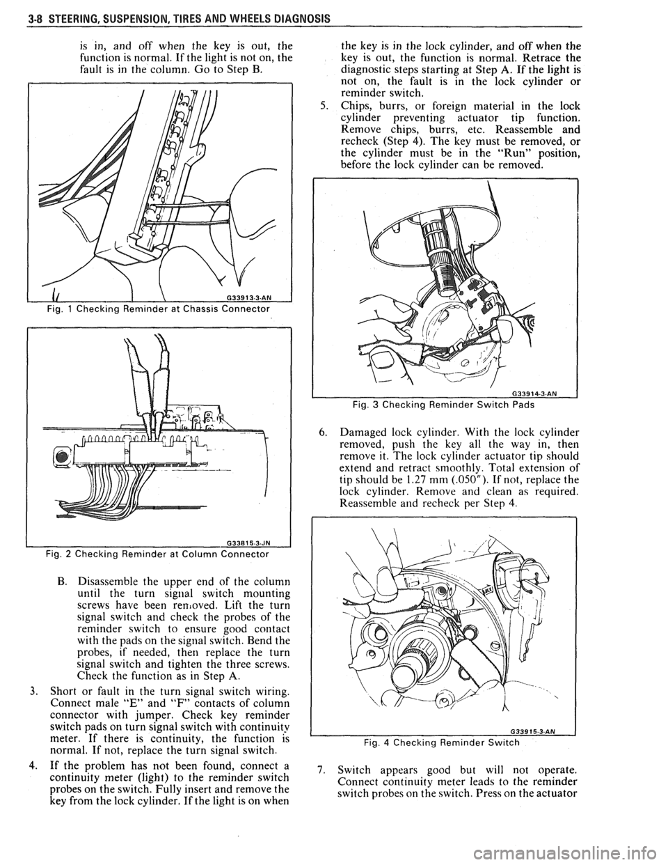
A. Connect a continuity meter (light) to the
male
"E" and "F" column connector
contacts. Push the key all the way into the
lock cylinder. If the light is on when the key
Page 133 of 1825
3-8 STEERING. SUSPENSION. TIRES AND WHEELS DIAGNOSIS
is in, and off when the key is out, the
function is normal. If the light is not on, the
fault is in the column. Go to Step B.
Fig. 1 Checking Reminder at Chassis Connector
Fig.
2 Checking Reminder at Column Connector
B. Disassemble the upper end of the column
until the turn
signal switch mounting
screws have been
removed. Lift the turn
signal switch and check the probes of the
reminder switch to ensure good contact
with the pads on the signal switch. Bend the
probes, if needed, then replace the turn
signal switch and tighten the three screws.
Check the function as in Step
A.
3. Short or fault in the turn signal switch wiring.
Connect male
"E" and "F" contacts of column
connector with jumper. Check key reminder
switch pads on turn signal switch with continuity
meter. If there is continuity, the function is
normal. If not, replace the turn signal switch. the
key is in the lock cylinder, and off when the
key is out, the function is normal. Retrace the
diagnostic steps starting at Step
A. If the light is
not on, the fault is in the lock cylinder or
reminder switch.
Chips, burrs, or foreign material in the lock
cylinder preventing actuator tip function.
Remove chips, burrs, etc. Reassemble and
recheck (Step 4). The key must be removed, or
the cylinder must be in the "Run" position,
before the lock cylinder can be removed.
Fig. 3 Checking Reminder Switch Pads
6. Damaged lock cylinder. With the lock cylinder
removed, push the key all the way in, then
remove it. The lock cylinder actuator tip should
extend and retract smoothly. Total extension of
tip should be
1.27 mm (.05OU). If not, replace the
lock cylinder. Remove and clean as required.
Reassemble
and recheck per Step 4.
Fig. 4 Checking Reminder Switch
4.. If the problem has not been found, connect a 7. switch appears good but will not operate, continuity meter (light) to the reminder switch
Connect continuity meter leads to the reminder
probes on the switch. Fully insert and remove the
switch probes on the switch. Press on the actuator
key from the lock cylinder. If the light is on when
Page 134 of 1825
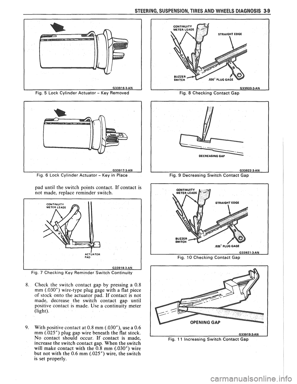
Fig. 5 Lock Cylinder Actuator - Key Removed
Fig.
6 Lock Cylinder Actuator - Key in Place
pad until the switch points contact. If contact is
not made, replace reminder switch.
I
ACTLATOR PAD
Fig. 7 Checking Key Reminder Switch Continuity
8.
Check the switch contact gap by pressing a 0.8
mm
(.03OU) wire-type plug gage with a flat piece
of stock onto the actuator pad. If contact is not
made, decrease the switch contact gap until
positive contact is made. Use a continuity meter
(light).
9. With positive contact at 0.8 mm (.03OU), use a 0.6
mm
(.025") plug gap wire beneath the flat stock.
No contact should occur.
If contact is made,
increase the switch contact gap. When the switch
will make contact with the 0.8 mm
(.030M) wire
but not with the 0.6 mm
(.025") wire, the switch
is set properly.
CONTINUITY
METERLEADS
Fig. 8 Checking Contact Gap
Fig.
9 Decreasing Switch Contact Gap
Fig.
10 Checking Contact Gap
OPENING GAP
Fig. 11 Increasing Switch Contact Gap
Page 135 of 1825

3-10 STEERING, SUSPENSION, TIRES AND WHEELS DIAGNOSIS
Reminder Keeps Operating With Key In Lock
Cylinder, Driver's Door Open Or Closed; Ceases
When Key Is Removed
Inspect
s Door jamb switch on driver's side misadjusted or
inoperative.
e Wire from signal switch to door jamb switch
shorted.
A. This condition indicates the lock cylinder or
the reminder switch is at fault. To verify,
check for continuity at the
"E" and "F"
male column connector contacts, with the
key removed from the lock cylinder. If
continuity exists, the fault is in the column.
B. Insert the key into the lock, then turn the
lock toward the "Start" position. If the
reminder stops when the key is in the
"Run" position or when it is turned past
"Run" toward "Start," the problem is a
sticky lock cylinder actuator.
COLUMN-MOUNTED DIMMER SWITCH
No "Low" or "High" Beam
Inspect
e Loose connector at dimmer switch
e Improper adjustment
e Internally damaged or worn switch. Check the
continuity on the switch at the It. green and at the
tan switch terminals by pushing in the plunger all
the way.
A click should be heard. If there is no
continuity, replace the dimmer switch. If there is
continuity, refer
to'section 8A for electricaldiag-
nosis.
PIVOT AND SWITCH ASSEMBLY
Switch Inoperative: No "Low," "High" and/or
"Wash"
e Loose body-to-switch connector
a Broken or damaged switch
Internally damaged or worn switch. Connect a
new switch without removing the old one. If the
system functions, replace the switch. If the
system doesn't function, refer to Section
8A for
electrical diagnosis.
STEERING GEAR AND PUMP LEAKS
General Procedure
Inspect
s Overfilled reservoir
s Fluid aeration and overflow
e , Hose connections
Verify exact point of leakage Example:
Torsion bar, stub shaft and
adjuster seals are close together; the exact
spot where the system is leaking may not be
clear.
Example: The point from which the fluid is
dripping is not necessarily the point where
the system is leaking; fluid overflowing from
the reservoir, for instance.
e When service is required:
A. Clean leakage area upon disassembly.
B. Replace leaking seal.
C. Check component sealing surfaces for
damage.
D. Reset bolt torque to specifications, where
required.
Some complaints about the power steering system
may be reported as:
A. Fluid leakage on garage floor
B. Fluid leaks visible on steering gear or pump
C. Growling noise, especially when parking or
when engine is cold
D. Loss of power steering when parking
E. Heavy steering effort
When troubleshooting these kinds of complaints,
check for an external leak in the power steering system.
For further diagnosis of leaks, refer to External
Leakage Check in this section.
External Leakage Check
Fig. 12
The purpose of this procedure is to pinpoint the
location of the leak.
In some cases, the leak can easily be located. But,
seepage-type leaks may be more difficult to isolate. To
locate seepage leaks, use the following method.
1. With the engine off, wipe dry the complete power
steering system.
2. Check the fluid level in the pump's reservoir. Add
fluid if necessary.
3. Start the engine, then turn the steering wheel
from stop to stop several times. Do not hold it at
a stop for any length of time, as this can damage
the power steering pump. It is easier if someone
else operates the steering wheel while you search
for the seepage.
4. Find the exact area of the leak and repair leak.
SEAL REPLACEMENT
RECOMMENDATIONS
Lip seals, which seal rotating shafts, require
special treatment. This type of seal is used on the
steering gear and on the drive shaft of the pump. When
there is a leak in one of these areas, always replace the
seal(s), after inspecting and thoroughly cleaning the
sealing surfaces. Replace the shaft only if very severe
pitting is found. If the corrosion in the lip seal contact
zone is slight, clean the surface of the shaft with crocus
cloth. Replace the shaft only if the leakage cannot be
stopped by first smoothing with crocus cloth.
Page 153 of 1825
385-2 STEERING WHEELS AND COLUMNS
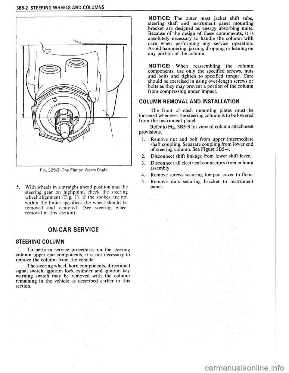
Fig. 385-2--The Flat on Worm Shaft
5. With wheels in a straight ahead position and the
steering gear on highpoint, check the steering
wheel alignment (Fig.
1). If the spokes are not
within the
limits specified, the wheel should be
removed
and centered. (See steering wheel
removal in this section).
NOTICE: The outer mast jacket shift tube,
steering shaft and instrument panel mounting
bracket are designed as energy absorbing units.
Because of the design of these components, it is
absolutely necessary to handle the column with
care when performing any service operation.
Avoid hammering, jarring, dropping or leaning on
any portion of the column.
NOTICE: When reassembling the column
components, use only the specified screws, nuts
and bolts and tighten to specified torque. Care
should be exercised in using over-length screws or
bolts as they may prevent a portion of the column
from compressing under impact.
I COLUMN REMOVAL AND INSTALLATION
The front of dash mounting plates must be
loosened whenever the steering column is to be lowered
from the instrument panel.
Refer to Fig. 3B5-3 for view of column attachment
provisions.
1. Remove nut and bolt from upper intermediate
shaft coupling. Separate coupling from lower end
of steering column. See Figure
3B5-4.
] 2. Disconnect shift linkage from lower shift lever.
3. Disconnect all electrical connectors from column
assembly.
4. Remove screws securing toe pan cover to floor
5. Remove nuts securing bracket to instrument
panel.
ON-CAR SERVICE
STEERING COLUMN
To perform service procedures on the steering
column upper end components, it is not necessary to
remove the column from the vehicle.
The steering wheel, horn components, directional
signal switch, ignition lock cylinder and ignition key
warning switch may be removed with the column
remaining in the vehicle as described earlier in this
section.