1988 PONTIAC FIERO key
[x] Cancel search: keyPage 1395 of 1825
WARNINGS AND ALARMS: CHIMES I
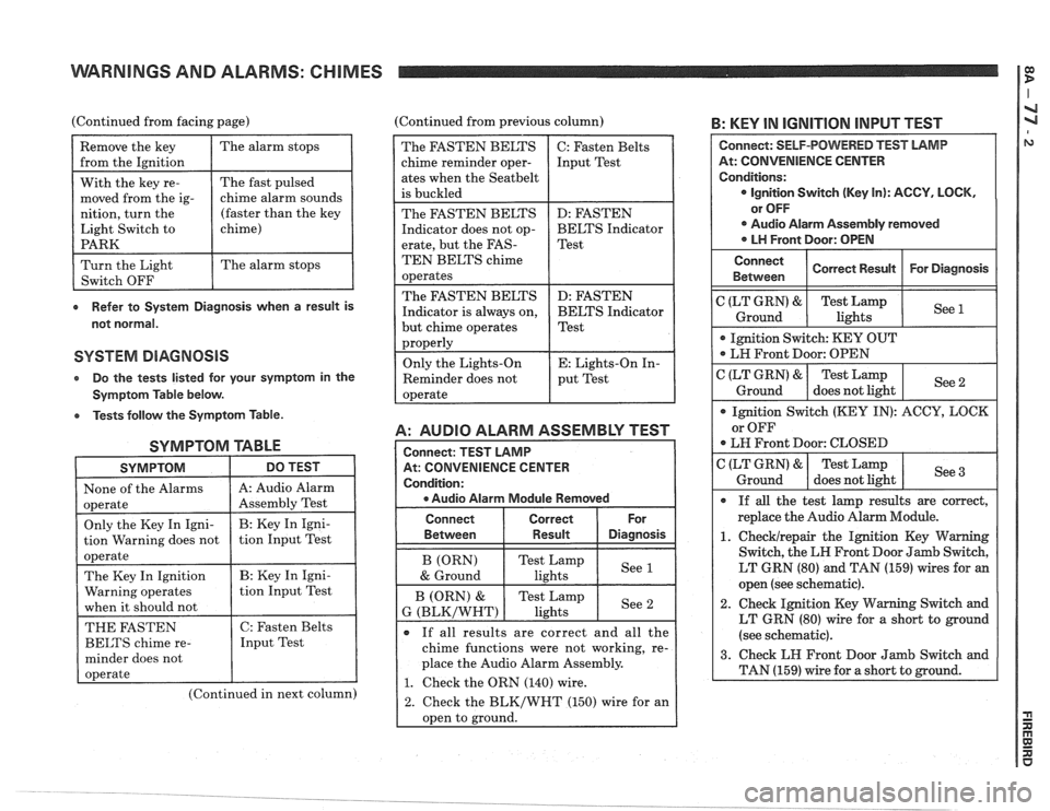
(Continued from facing page) (Continued from previous column) B: KEY IN IGNITION INPUT TEST
e Refer to System Diagnosis when a result is
not normal.
SYSTEM DIAGNOSIS
Do the tests listed lor your symptom in the
Symptom Table below.
e Tests follow the Symptom Table.
SYMPTOM TABLE
SYMPTOM DO TEST I
1 None of the Alarms 1 A: Audio Alarm I
(Continued in next column)
A: AUDIO ALARM ASSEMBLY TEST
At: CONVENIENCE CENTER
e Audio Alarm Module Removed
The FASTEN BELTS
chime reminder oper-
ates when the
Seatbelt
is buckled
The FASTEN BELTS
Indicator does not op-
erate, but the
FAS-
TEN BELTS chime
operates
The FASTEN BELTS
Indicator is always on,
but chime operates
properly
Only the Lights-On
Reminder does not
operate
Connect Correct
Between
I Result Diasnosis
C: Fasten Belts
Input Test
D: FASTEN
BELTS Indicator
Test
D: FASTEN
BELTS Indicator
Test
E: Lights-On In-
put Test
If all results are correct and all the
chime functions were not working, re-
place the Audio Alarm Assembly.
1. Check the ORN (140) wire.
2. Check the BLK/WHT (150) wire for an
oDen to ground.
At: CONVENIENCE CENTER
LT GRN (80) and TAN (159) wires for an
open (see schematic).
2. Check Ignition Key Warning Switch and
LT GRN (80) wire for a short to ground
(see schematic).
Page 1397 of 1825
WARNINGS AND ALARMS: CHIMES
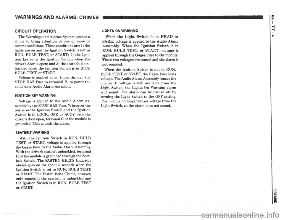
GlRGUlT OPERATION
The Warnings and Alarms System sounds a
chime to bring attention to one or more of
several conditions. These conditions are:
1) the
lights are on and the Ignition Switch is not in
RUN, BULB TEST, or START;
2) the Igni-
tion key is in the Ignition Switch when the
driver's door is open; and
3) the seatbelt is un-
buckled when the Ignition Switch is in RUN,
BULB TEST, or START.
Voltage is applied at all times through the
STOP
HAZ Fuse to terminal B, to power the
solid state Audio Alarm Assembly.
IGNITION KEY VVARNING
Voltage is applied to the Audio Alarm As-
sembly by the STOP HAZ Fuse. Whenever the
key is in the Ignition Switch and the Ignition
Switch is in LOCK, OFF, or ACCY with the
driver's door open, terminal C of the module is
grounded. This sounds the alarm.
LIGHTS-ON WARNING
When the Light Switch is in HEAD or
PARK, voltage
is applied to the Audio Alarm
Assembly. When the Ignition Switch
is in
RUN, BULB TEST, or START, voltage is
applied through the Gages Fuse to the module.
These two voltages are sensed and the alarm is
not sounded.
When the Ignition Switch is not in RUN,
BULB TEST, or START, the Gages Fuse loses
voltage. The Audio Alarm Assembly senses the
change. If voltage is still available from the
Light Switch, the Lights-On Warning alarm
will sound. The alarm can be turned off by
turning the Light Switch to the OFF setting.
The module no longer senses voltage from the
Light Switch, so the alarm does not sound.
SEATBELT WARNING
With the Ignition Switch in RUN, BULB
TEST, or START, voltage is applied through
the Gages Fuse to the Audio Alarm Assembly.
With the driver's
seatbelt unbuckled, terminal
H of the module is grounded through the Seat-
belt Switch. The FASTEN BELTS Indicator
always goes on for about
5 seconds when the
Ignition Switch is set to RUN, BULB TEST,
or START. The Fasten Belts Chime, however,
only sounds if the
seatbelt is unbuckled and
the Ignition Switch
is in RUN, BULB TEST
or START
Page 1511 of 1825
THEFT DETERRENT SYSTEM: PASSKEY !E
FUSE BLOCK
CLUTCH PEDAL
KEY
-
Page 1512 of 1825
THEFT DETERRENT SYSTEM: PASSKEY I a
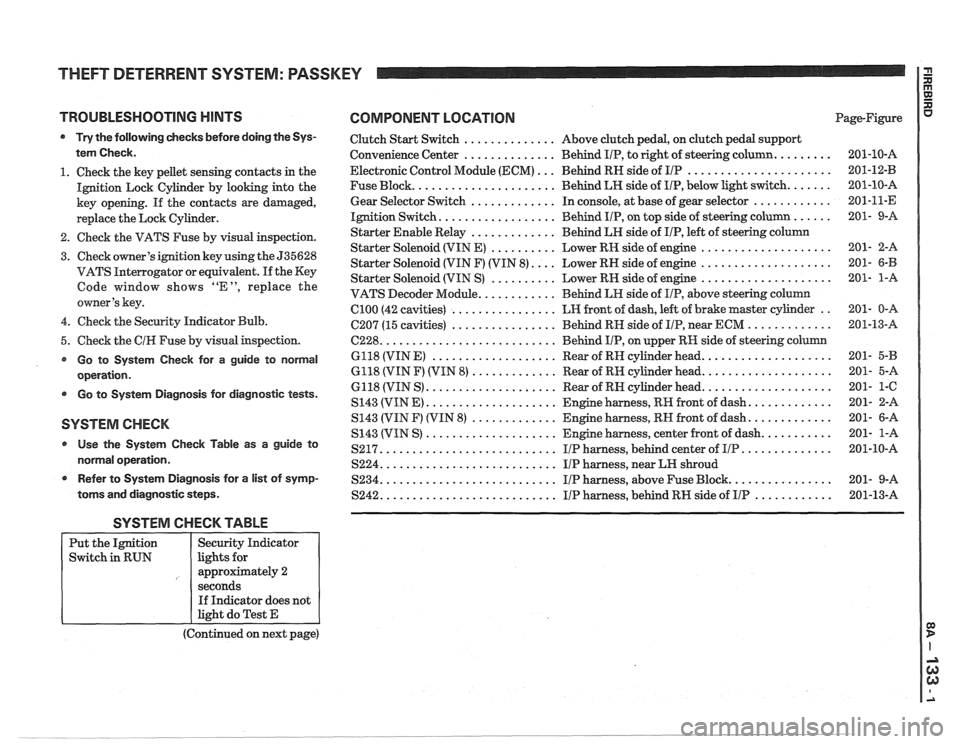
TROUBLESHOOTING HINTS COMPONENT LOCATION
Try the following checks before doing the Sys-
tem Check.
1. Check the key pellet sensing contacts in the
Ignition Lock Cylinder by looking into the
key opening. If the contacts are damaged,
replace the Lock Cylinder.
2. Check the VATS Fuse by visual inspection.
3. Check owner's ignition key using the 535628
VATS Interrogator or equivalent.
If the Key
Code window shows "E", replace the
owner's key.
4. Check the Security Indicator Bulb.
5. Check the
CIH Fuse by visual inspection.
Go to System Check for a guide to normal
operation.
Go to System Diagnosis for diagnostic tests.
SYSTEM CHECK
Use the System Check Table as a guide to
normal operation.
r Refer to System Diagnosis for a list of symp-
toms and diagnostic steps.
Clutch Start Switch .............. Above clutch pedal, on clutch pedal support
Convenience Center
.............. Behind IIP, to right of steering column. ........
Electronic Control Module (ECM) ... Behind RN side of IIP ......................
Fuse Block. ..................... Behind LH side of IIP, below light switch. ......
Gear Selector Switch ............. In console, at base of gear selector ............
Ignition Switch. ................. Behind IIP, on top side of steering column ......
Starter Enable Relay ............. Behind LH side of IIP, left of steering column
Starter Solenoid (VIN E)
.......... Lower RH side of engine ....................
Starter Solenoid (VIN F) (VIN 8). ... Lower RH side of engine ....................
Starter Solenoid (VIN S) .......... Lower RN side of engine ....................
VATS Decoder Module. ........... Behind LH side of IIP, above steering column
Cl00 (42 cavities) ................ LH front of dash, left of brake master cylinder ..
C207 (15 cavities) ................ Behind RN side of IIP, near ECM .............
6228. .......................... Behind IIP, on upper RH side of steering column
6118 (VIN
E) ................... Rear of RN cylinder head. ...................
6118 (VIN F) (VIN 8) ............. Rear of RH cylinder head. ...................
6118 (VIN S) .................... Rear of RN cylinder head. ...................
S143 (VIN E) .................... Engine harness, RR front of dash. ............
S143 (VIN F) (VIN 8) ............. Engine harness, RN front of dash. ............
S143 (VIN S) .................... Engine harness, center front of dash. ..........
S217. .......................... IIP harness, behind center of IIP. .............
S224. .......................... IIP harness, near LH shroud
S234. .......................... I/P harness, above Fuse Block. ...............
S242. .......................... IIP harness, behind RH side of IIP ............
SYSTEM CHECK TABLE
(Continued on next page)
Put
the Ignition
Switch in RUN
R aJ XI
Page-Figure u
Security Indicator
lights for
approximately 2
seconds If Indicator does not
light do Test E
Page 1513 of 1825
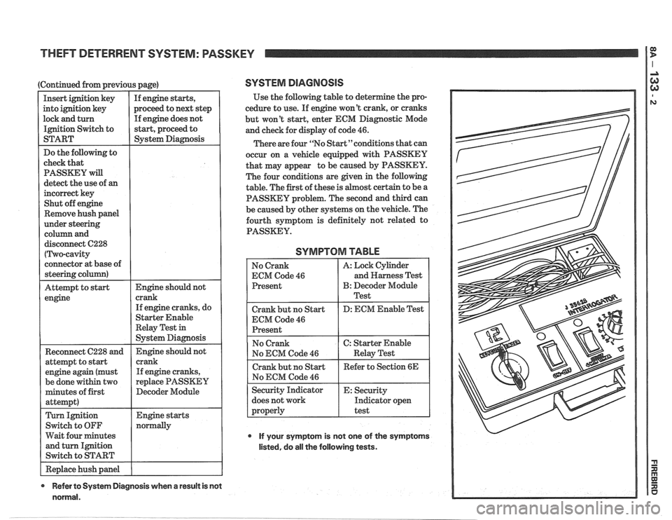
THEFT DETERRENT SYSTEM: PASSKEY
(Continued from previous page)
If engine does not
Remove hush panel
disconnect C228
( Two-cavity
connector at base of
steering column)
Attempt to
start Engine should not
engine
Reconnect C228 and
attempt to start
engine again (must
be done within two
minutes of first
attempt)
Turn Ignition
Switch to
OFF
Wait four minutes
and turn Ignition
Switch to START crank
If engine cranks, do
Starter Enable
Relay Test
in
System Diagnosis
Engine should not
crank If engine cranks,
replace PASSKEY
I Decoder Module
I Replace hush panel 1 I
SYSTEM DIAGNOSIS
Use the following table to deter
cedure to use. If engine won't crank, or cranks
but won't start, enter ECM Diagnostic Mode
and check for display of code
46.
There are four "No Start"conditions that can
occur on a vehicle equipped with PASSKEY
that may appear to be caused by PASSKEY.
The four conditions are given in the following
table. The first of these is
host certain to be a
PASSKEY problem. The second and third can
be caused by other systems on the vehicle. The
fourth symptom is definitely not related to
PASSKEY.
SYMPTOM TABLE
No Crank
ECM Code
46
Present
Crank but no Start
ECM Code
46
Present A:
Lock Cylinder
and Harness Test
B: Decoder Module
Test
D: ECM Enable Test
No ECM Code
46
does not work Indicator open
If your symptom is not one of the symptoms
listed, do all the following tests.
* Refer to System Diagnosis when a result is not
normal.
Page 1514 of 1825
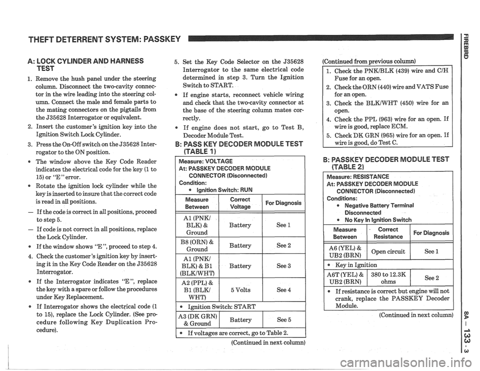
THEFT DETERRENT SYSTEM: PASSKEY I i
A: LOCK CYLINDER AND HARNESS
TEST
1. Remove the hush panel under the steering
column. Disconnect the two-cavity connec-
tor in the wire leading into the steering col-
umn. Connect the male and female parts to
the mating connectors on the pigtails from
the 535628 Interrogator or equivalent.
2. Insert the customer's ignition key into the
Ignition Switch Lock Cylinder.
3. Press the On-Off switch on the 535628 Inter-
rogator to the ON position.
* The window above the Key Code Reader
indicates the electrical code for the key
(1 to
15) or
"En error.
Rotate the ignition lock cylinder while the
key is inserted to insure that the correct code
is read in all positions.
- If the code is correct in all positions, proceed
to step 5.
- If code is not correct in all positions, replace
the Lock Cylinder.
* If the window shows "E ", proceed to step 4.
4. Check the customer's ignition key by insert-
ing it in the Key Code Reader on the 535628
Interrogator.
If the Interrogator indicates
"EM, replace
the key with a spare or follow the procedures
under Key Replacement.
If Interrogator shows the electrical code
(1
to 15), replace the Lock Cylinder. (See pro-
cedure following Key Duplication Pro-
cedure). 5.
Set the Key Code Selector on the 535628
Interrogator to the same electrical code
determined in step 3. Turn the Ignition
Switch to START.
If engine starts, reconnect vehicle wiring
and check that the two-cavity connector at
the base of the steering column mates cor-
rectly.
If engine does not start, go to Test B,
Decoder Module Test.
B: PASS KEY DECODER MODULE TEST
(TABLE
1 )
At: PASSKEY DECODER MODULE
CONNECTOR (Disconnected)
Condition:
1 . 1mition switch: START I
Ignition Switch: RUN
Continued from previous c
1. Check the PNKIBLK (439) wire and ClN
Fuse for an open.
2. Check the ORN (440) wire and VATS Fuse
for an open.
3. Check the
BLKIWT (450) wire for an
open.
4. Check the PPL (963) wire for an open.
If
wire is good, replace ECM.
5. Check DK GRN (965) wire for an open. If
wire is good, do Test C.
For Diagnosis
See 1
See 2
See 3
See 4
Measure
Between
A1 (PNKI
BLK) &
Ground
(ORN' &
Ground
A1 (PNKI
BLK)
& I31
(BLKIWNT)
A2 (PPL) &
Bl (BLKI
WNT)
B: PASSKEY DECODER MODULE TEST
Correct
Voltage
Battery
Battery
Battery
5 Volts
(TABLE 2)
Measure: RESISTANCE
At: PASSKEY DECODER MODULE
CONNECTOR (Disconnected)
Conditions: Negative Battery Terminal
Disconnected
r No lCev ln lainition Switch
Measure
- Correct For Diagnosis
Between Resistance
& open circuit
UB2 (BRN) See 1
crank,
replace the PASSKEY Decoder
Module.
-
(Continued in next column) A3 (DK GRN)
& Ground
I . If voltages are correct, go to Table 2.
(Continued in next column)
Battery See 5
Page 1515 of 1825
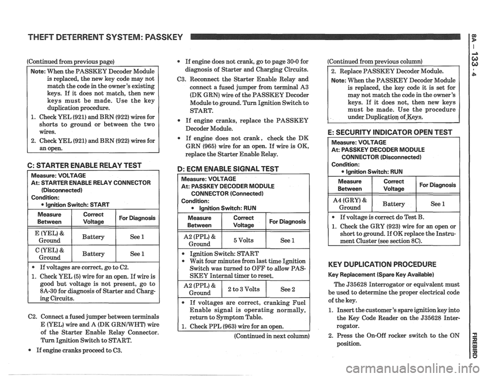
Continued from previous page)
Note: VVhen the PASSKEY Decoder Module
is replaced, the new key code may not
match the code in the owner's existing
keys. If it does not match, then new
keys must be made. Use the key
duplication procedure.
1. Check YEL (921) and BRN (922) wires for
shorts to ground or between the two
wires.
2. Check
UEL (921) and BRN (922) wires for
an open. If
engine does not crank, go to page 30-0 for
diagnosis of Starter and Charging Circuits.
C3. Reconnect the Starter Enable Relay and
connect a fused jumper from terminal A3
(DK GRN) wire of the PASSKEY Decoder
Module to ground. Ignition Switch to
START.
0 If engine cranks, replace the PASSKEY
Decoder Module.
If engine does not crank, check the DK
GRN (965) wire for
an open. If wire is OK,
replace the Starter Enable Relay.
6: STARTER ENABLE RELAY TEST
D: ECM ENABLE SIGNAL TEST
C2. Connect a fused jumper between terminals
Measure: VOLTAGE
At: STARTER ENABLE RELAY CONNECTOR
(Disconnected)
Condition:
0 Ignition Switch: START Measure:
VOLTAGE
At: PASSKEY DECODER MODULE
CONNECTOR (Connected)
Condition: 0 Ignition Switch: RUN
Measure
Between
&
Ground
&
Ground
Measure
Between I I For Diagnosis ( Voltage
1 I 5Volts I See 1 1
If voltages are correct, go to C2.
1. Check YEL (5) wire for an open. If wire is
good but voltage is not present, go to
8A-30 for diagnosis of Starter and Charg-
ing Circuits.
Correct
Voltage
Battery
Battery
I I
Ignition Switch: START
For Diagnosis
See 1
See 1
0 wait four minutes from last time Ignition
Switch was turned to OFF to
allow PAS-
SKEY Internal timer to reset.
I A2 IPPL)& ) 2 to3Volts I See2 i Ground
If voltages are correct, cranking Fuel
Enable signal is operating normally,
return to Symptom Table.
E (YEL) Vfire and A (DK GR wire 1 1. Check PPL (963) wire for an open. A of the Starter Enable Relay Connector. I I
(Continued in next column)
Ignition Switch to START.
If engine cranks proceed to
63.
Continued from previous column)
2. Replace PASSKEY Decoder Module.
Note: When the PASSKEY Decoder Module
is replaced, the key code
it is set for
may not match the code in the owner's
keys. If
it does not, then new keys
must be made. Use the procedure
under
Duplicgti~n of-Keys2
E: SECURITY INDICATOR OPEN TEST
CONNECTOR (Disconnected)
Condition:
KEY DUPLICATION PROCEDURE
Key Replacement (Spare Key Available)
The 535628 Interrogator or equivalent must
be used to det e
the proper electrical code
of the key.
1. Insert the customer's spare ignition key into
the Key Code Reader on the 535628 Inter-
rogator.
2. Press the On-Off rocker switch to the ON
position.
Page 1516 of 1825
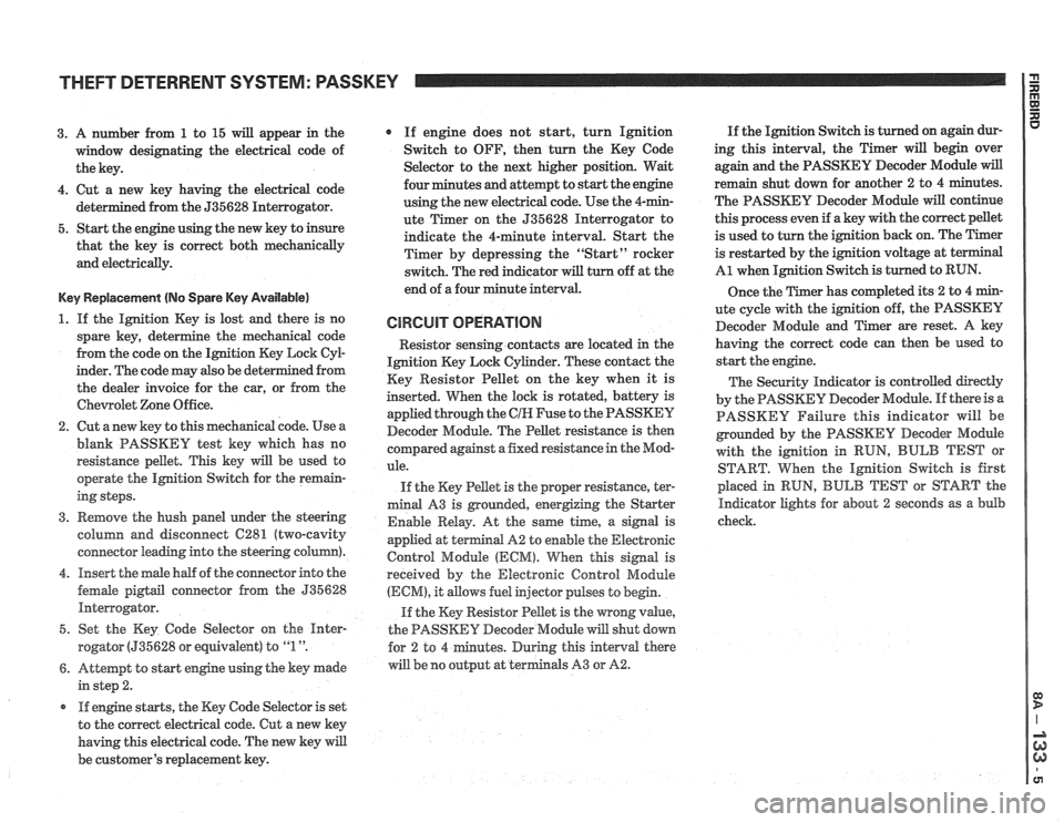
THEFT DETERRENT SYSTEM: PASSKEY
3. A number from 1 to 15 will appear in the
window designating the electrical code of
the key.
4. Cut a new key having the electrical code
ed from the 535628 Interrogator.
5. Start the engine using the new key to insure
that the key is correct both mechanically
and electrically.
Key Replacement (No Spare Key Available)
1. If the Ignition Key is lost and there is no
spare key, determine the mechanical code
from the code on the Ignition Key Lock
CyE
inder. The code may also be det
the dealer invoice for the car, or from the
Chewolet Zone Office.
2. Cut anew key to this mechanical code. Use a
blank PASSKEY test key which has no
resistance pellet. This key will be used to
operate the Ignition Switch for the remain-
ing steps.
3. Remove the hush panel under the steering
column and disconnect
C281 (two-cavity
connector leading into the steering column).
4. Insert the male half of the connector into the
female
pigtail connector from the 535628
Interrogator.
5. Set the Key Code Selector on the
Hnter-
rogator (535628 or equivalent) to "1 ".
6. Attempt to start engine using the key made
in step 2.
r If engine starts, the Key Code Selector is set
to the correct electrical code. Cut a new key
having this electrical code. The new key will
be customer's replacement key.
If engine does not start, turn Ignition
Switch to OFF, then turn the Key Code
Selector to the next higher position. Wait
four minutes and attempt to start the engine
using the new electrical code. Use the 4-min-
ute Timer on the 535628 Interrogator to
indicate the 4-minute interval. Start the
Timer by depressing the "Start" rocker
switch. The red indicator
will turn off at the
end of a four minute interval.
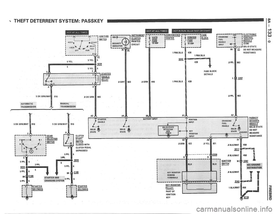
CIRCUIT OPERATION
Resistor senshg contacts are located in the
Ignition Key Lock Cylinder. These contact the
Key Resistor Pellet on the key when it is
inserted. When the lock is rotated, battery is
applied through the
CIH Fuse to the PASSKEY
Decoder Module. The Pellet resistance is then
colnpared against a fixed resistance in the Mod-
ule.
If the Key Pellet is the proper resistance, ter-
minal A3 is grounded, energizing the Starter
Enable Relay. At the
same time, a signal is
appfied at terminal A2 to enable the Electronic
Control Module
(ECM). When this signal is
received by the Electronic Control Module
(ECM), it allows fuel injector pulses to begin.
If the Key Resistor Pellet is the wrong
value,
the PASSKEY Decoder Module will shut down
tes. During this interval there
will be no output at terminals A3 or
A2.
If the Ignition Switch is turned on again dur-
ing this interval, the Timer will begin over
again and the PASSKEY Decoder Module
will
remain shut down for another 2 to 4 minutes.
The PASSKEY Decoder Module will continue
this process even if a key with the correct pellet
is used to turn the ignition back on. The Timer
is restarted by the ignition voltage at
t
A1 when Ignition Switch is turned to RUN.
Once the Timer has completed its
2 to 4 min-
ute cycle with the ignition off, the PASSKEY
Decoder Module and Timer are reset. A key
having the correct code can then be used to
start the engine.
The Security Indicator is controlled directly
by the PASSKEY Decoder Module. If there is a
PASSKEY Failure this indicator will be
grounded by the PASSKEY
Decoder Module
with the ignition in RUN,
BULB TEST or
START. When the Ignition Switch is first
placed in
RUN, BULB TEST or START the
Indicator lights for about 2 seconds as a bulb
check.