1988 PONTIAC FIERO oil
[x] Cancel search: oilPage 1427 of 1825
BNS'TWUMENT PANEL: DIGITAL CLUSTER a B
(Continued from previous gage)
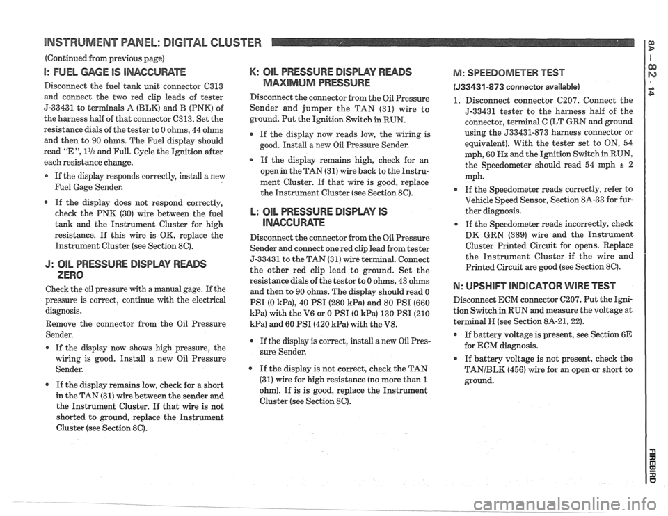
I: FUEL GAGE IS INACCUWTE
Disconnect the fuel tank unit connector C313
and connect the two red clip leads of tester
5-33431 to
terminals A (BLK) and B (PNK) of
the harness half of that connector
C313. Set the
resistance
dials of the tester to 0 ohms, 44 ohms
and then to 90 ohms. The Fuel display should
read
"E ", 11/2 and Full. Cycle the Ignition after
each resistance change.
If the display responds correctly, install a new
Fuel Gage Sender.
If the display does not respond correctly,
check the PNK (30) wire between the fuel
tank and the Instrument Cluster for high
resistance.
If this wire is OK, replace the
Instrument Cluster (see Section
8C).
J: OIL PRESSURE DISIDWY READS
ZERO
Check the oil pressure with a manual gage. If the
pressure is correct, continue with the electrical
diagnosis.
Remove the connector from the Oil Pressure
Sender.
If the display now shows high pressure, the
wiring is good. Install a new Oil Pressure
Sender.
If the display remains low, check for a short
in the TAN (31)
wire between the sender and
the Instrument Cluster. If that wire is not
shorted to ground, replace the Instrument
Cluster (see Section
8C).
K: OIL PRESSURE DISPWY RWDS
MMlMklM PRESSURE
Disconnect the connector from the Oil Pressure
Sender and jumper the TAN (31) wire to
ground. Put the Ignition Switch in RUN.
If the display now reads low, the wiring is
good. Install a new
Oil Pressure Sender.
* If the display remains high, check for an
open in the TAN (31) wire back to the Instru-
ment Cluster. If that wire is good, replace
the Instrument Cluster (see Section
8C).
L: OIL PRESSURE BlSPLAV IS
llUAGCll RATE
Disconnect the connector from the Oil Pressure
Sender and connect one red clip lead from tester
5-3343
1 to the TAN (3 1) wire terminal. Connect
the other red clip lead to ground. Set the
resistance dials of the
testor to 0 ohms, 43 ohms
and then to 90 ohms. The display should read 0
PSI (0
kPa), 40 PSI (280 kPa) and 80 PSI (660
kPa) with the V6 or 0 PSI (0 kPa) 130 PSI (210
kPa) and 60 PSI (420 kPa) with the V8.
r If the display is correct, install a new Oil Pres-
sure Sender.
If the display is not correct, check the TAN
(31) wire for high resistance (no more than
1
ohm). If is is good, replace the Instrument
Cluster (see Section
8C).
M: SPEEDOMETER BEST
(533431 -873 conneetor available)
1. Disconnect connector C207. Connect the
5-33431 tester to the harness
half of the
connector, terminal
C (LT GRN and ground
using the
533431-873 harness connector or
equivalent). With the tester set to
ON, 54
mph, 60
Hz and the Ignition Switch in RUN,
the Speedometer should read 54
qh + 2
mph.
If the Speedometer reads correctly, refer to
Vehicle Speed Sensor, Section
8A-33 for fur-
ther diagnosis.
If the Speedometer reads incorrectly, check
DK GRN (389) wire and the Instrument
Cluster Printed Circuit for opens. Replace
the Instrument Cluster if the wire and
Printed Circuit are good (see Section
8C).
N: UPSHIFT lNDlCATOR WIRE TEST
Disconnect ECM connector C207. Put the Igni-
tion Switch
in RUN and measure the voltage at
terminal
N (see Section 8A-21,221.
If battery voltage is present, see Section 6E
for ECM diagnosis.
If battery voltage is not present, check the
TANIBLK (456) wire for an open or short to
ground.
Page 1428 of 1825
INSTRUMENT PANEL: DIGITAL CLUSTER n 23 rn E
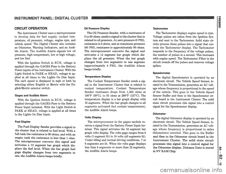
ClRCUlT OPERATION
The Instrument Cluster uses a microprocessor
to develop data for fuel supply, coolant tem-
perature, oil pressure, voltage, engine rpm, and
vehicle speed. The Digital Cluster also contains
an Odometer, Warning Indicators, and an Audi-
ble Alarm. The Audible Alarm signals low oil
pressure, high temperature, low or high voltage,
and low fuel.
With the Ignition Switch in RUN, voltage is
applied through the GAGES Fuse to the Battery
Power inputs of the Instrument Cluster. With the
Light Switch in PARK or HEAD, voltage is ap-
plied at all times to the Lights On Dim Input.
The car's speed is displayed in mph or
krnh by
selecting either English or Metric with the
En-
glishNetric selector switch.
Gages and Audible Alarm
With the Ignition Switch in RUN, voltage is
applied through the GAGES Fuse to the Battery
Power Input terminal. With the Light Switch in
PARK or HEAD, voltage is applied at all times
to the Lights On Dim Input.
Fuel Display
The Fuel Display Sender provides a signal to
the cluster that is related to fuel level. With a
full tank the resistance is 90 ohms, and with an
empty tank the resistance is less than
1 ohm.
The microprocessor converts this signal and
activates a 12 segment bar graph which dis-
plays the fuel level. When the bar graph fuel
gage display changes from two segments to
one, the Audible Alarm beeps briefly.
Oil Pressure Display
The Oil Pressure Sender, with a resistance of
0 to 90 ohms, sends a signal to the cluster that is
related
to oil pressure. At zero pressure (0 PSI),
resistance is 0 ohms, and at maximum pressure
(80 PSI), resistance is approximately 90 ohms.
The microprocessor converts the signal and
activates a 12 segment bar graph which dis-
plays the oil pressure. When the bar graph
changes from two segments to one segment
(approximately
4 PSI), the Audible Alarm
beeps briefly.
kmperature Display
The Coolant Temperature Sender sends a sig-
nal to the Instrument Cluster that is related to
coolant temperature. Coolant Temperature
Sender resistance drops from 1,365 ohms at
100°F
(38"C), to 55 ohms at 260°F (127°C). The
temperature display is a bar graph display with
12 segments. When the bar graph changes to all
segments activated (hot coolant temperature),
the Audible Alarm beeps.
Volts Display
The microprocessor in the gages module re-
ceives a signal from the Battery Power Input ter-
minal. This signal activates the 12 segment bar
graph volts display. The volts gage ranges from 8
volts
(1 segment lit) to 18 volts (all segments lit).
Under idling and normal driving conditions, 7 or
8 segments are lit. When the volts gage displays
less than
4 segments or more than 12 segments,
the Audible Alarm beeps.
Tachometer
The Thchometer displays engine speed in rpm.
Voltage pulses are taken from the
Ignition Sys-
tem and sent to the Tachometer. Solid state cir-
cuits process these pulses into a signal that con-
trols the Tachometer display. The Tachometer
responds to the frequency of the voltage pulses,
the number of pulses in a second. This increases
with engine speed. The
'Pdchometer Filter in the
circuit rounds off the pulses and removes voltage
spikes.
Speedometer
The digital Speedometer is operated by an
electronic circuit. The Vehicle Speed Sensor, lo-
cated in the Transmission, generates an AC volt-
age whose frequency is proportional to the speed
of the vehicle. This goes to the Vehicle Speed
Sensor Buffer and then to the Speedometer cir-
cuit board in the Instrument Cluster. The solid
state circuit processes this signal into a control
signal for the Speedometer display.
Odometer
The digital Odometer display is operated by an
electronic circuit. The Vehicle Speed Sensor, lo-
cated in the Transmission, generates an
AC volt-
age whose frequency is proportional to miles
(kilometers) traveled. This goes to the Buffer
and then to the Odometer circuit board in the
Instrument Cluster. The solid state circuit
processes this signal into a control signal for
the Odometer display. Distance Data is stored
in
NV RAM Chip.
Page 1455 of 1825
HEADLIGHTS: FOG LIGHTS
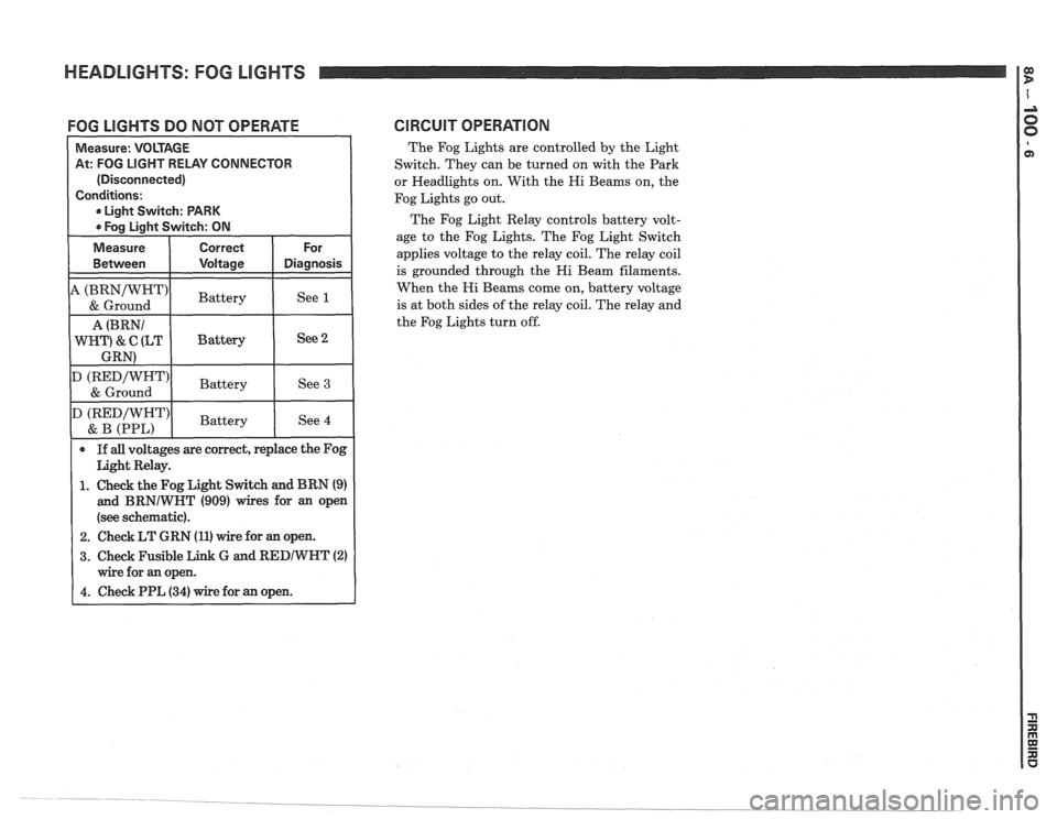
FOG LIGHTS DO NOT OPERATE CIRCUIT OPERATlON
The Fog Lights are controlled by the Light
Switch. They can be turned on with the Park
or Headlights on. With the Hi Beams on, the
Fog Lights go out.
The Fog Light Relay controls battery volt-
age to the Fog Lights. The Fog Light Switch
applies voltage to the relay coil. The relay coil
is grounded through the Hi Beam filaments.
When the Hi Beams come on, battery voltage
is at both sides of the relay coil. The relay and
the Fog Lights turn off.
At: FOG LIGHT RELAY CONNECTOR
(Disconnected)
1. Check the Fog Light Switch and BRN (9)
and BRNIWNT (909) wires for an open
(see schematic).
2. Check LT GRN (11) wire for an open.
3. Check Fusible Link G and RED/WNT (2)
Page 1467 of 1825
HEADLIGHTS WITH LAMP MONITOR: FOG LIGHTS
I7
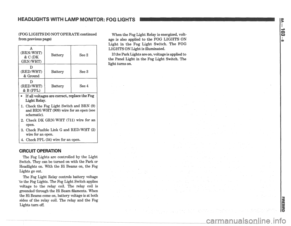
(FOG LIGHTS DO NOT OPERATE continued
When the Fog Light Relay is energized, volt-
from previous page)
age is also applied to the FOG LIGHTS ON
Light in the Fog Light Switch. The FOG
LIGHTS ON Light is ated.
If the Park Lights are on, voltage is applied to
the Panel Light in the Fog Light Switch. The
light turns on.
CIRCUIT OPEWTIOIU
The Fog Lights are controlled by the Light
Switch. They can be turned on with the Park or
Headlights on. With the Hi Beams on, the Fog
Lights go out.
The Fog Light Relay controls battery voltage
'to the Fog Lights. The Fog Light Switch applies
voltage to the relay coil. The relay coil is
grounded through the Hi Beam filaments. When
the Hi Beams come on, battery voltage is at both
sides of the relay coil. The relay and the Fog
Lights turn off.
A
(BRNJWHT)
& C (DK
GRNIWHT)
D
(REDIWHT)
& Ground
D
(REDIWHT)
& B (PPL)
If all voltages are correct, replace the Fog
Light Relay.
1. Check the Fog Light Switch and BRN (9)
and
BRNIWHT (909) wire for an open (see
schematic).
2. Check DK GRNIWNT (711) wire for an
open.
3. Check Fusible Link G and REDJWHT (2)
wire for an open.
4. Check PPL (34) wire for an open.
Battery
Battery
Battery See
2
See 3
See 4
Page 1510 of 1825
POWER DOOR LOCKS
(Continued from previous facing page)
TAN (294) and GRY (295) wires for
opens (see schematic). If the wires are
OK, do Test A.
1. Check the LT BLU (195) wire for an open
(see schematic). If the
wire is good, do Test
2. Check the BLK (194) wire for an open
(see schematic). If the wire is good, do
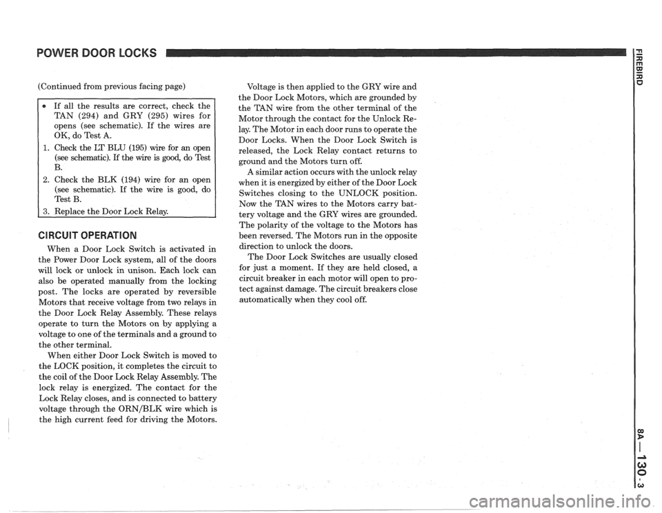
CIRCUIT OPERATION
When a Door Lock Switch is activated in
the Power Door Lock system, all of the doors
will lock or unlock in unison. Each lock can
also be operated manually from the locking
post. The locks are operated by reversible
Motors that receive voltage from two relays in
the Door Lock Relay Assembly. These relays
operate to turn the Motors on by applying a
voltage to one of the terminals and a ground to
the other terminal.
When either Door Lock Switch is moved to
the LOCK position, it completes the circuit to
the coil of the Door Lock Relay Assembly. The
lock relay is energized. The contact for the
Lock Relay closes, and is connected to battery
voltage through the
ORNIBLK wire which is
the high current feed for driving the Motors. Voltage
is then applied to the GRY wire and
the Door Lock Motors, which are grounded by
the TAN wire from the other terminal of the
Motor through the contact for the Unlock Re-
lay. The Motor in each door runs to operate the
Door Locks. When the Door Lock Switch is
released, the Lock Relay contact returns to
ground and the Motors turn off.
A similar action occurs with the unlock relay
when it is energized by either of the Door Lock
Switches closing to the UNLOCK position.
Now the TAN wires to the Motors carry bat-
tery voltage and the GRY wires are grounded.
The polarity of the voltage to the Motors has
been reversed. The Motors run in the opposite
direction to unlock the doors.
The Door Lock Switches are usually closed
for just a moment. If they are held closed, a
circuit breaker in each motor will open to pro-
tect against damage. The circuit breakers close
automatically when they cool off.
Page 1521 of 1825
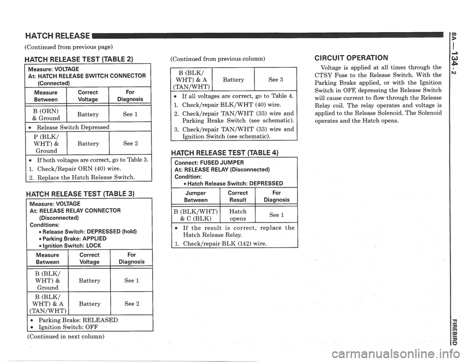
HATCH RELEASE 1:
(Continued from previous page) I
MATGH RELEASE TEST (TABLE 2)
Measure: VOLTAGE
At: HATCH RELEASE
SVVITCH CONNECTOR
[Connected)
-re I Correct I or I
Between I Voltage I Diagnosis I I
1 -a Release Switch De~ressed I
(ORN)
& Ground
HAKH RELEASE TEST (TABLE 3)
Measure: VOLTAGE
At: RELEASE RELAY CONNECTOR
(Disconnected)
Conditions:
0 Release Switch: DEPRESSED (hold)
r Parking Brake: APPLIED
a lanition Switch: LOCK
Battery (Continued from
previous column)
See 1
1. Checklrepair BLK/WHT (40) wire.
2. Checklrepair TAN/WHT (33) wire and
Parking Brake Switch (see schematic).
HATGH RELEASE TEST (TABLE 4)
Connect: FUSED JUMPER
At: RELEASE RELAY (Disconnected)
Condition:
a Hatch Release Switch: DEPRESSED
Jumper Correct For
Between Result Diagnosis
B (BLKIWHT) Hatch
& C (BLK) See 1 opens
e If
the result is correct, replace the
Hatch Release Relay.
1. Checklrepair BLK (142) wire.
CIRCUIT OPERATION
Voltage is applied at all times through the
CTSY Fuse to the Release Switch. With the
Parking Brake applied, or with, the Ignition
Switch in
OFF, depressing the Release Switch
will cause current to flow through the Release
Relay coil. The relay operates and voltage is
applied to the Release Solenoid. The Solenoid
operates and the Hatch opens.
(Continued in next column)
Page 1553 of 1825
RADIO I
(Continued from previous page) from back of Radio
If noise persists with replacement antenna, the
problem must be repaired at the source of noise
(generator, ignition system, accessory, etc.). See
Delco Manual for noise "Sniffing" procedures.
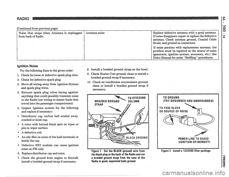
Ignition Noise
Trv the following. fixes in the piven order: 8. Install a braided ground strap on the hood. Replace
defective antenna with a good antenna.
If noise disappears repair or replace the defective
antenna. Check antenna ground, Coaxial Cable
Braid, and ground at connectors.
unplugged
- -
1. Check
for loose or defective spark plug wire.
2. Check for defective spark plug.
3. Move all wiring away from Ignition System
and spark plug wires. Antenna
noise
4. Reroute spark plug wires laying against
anything that could possibly transmit noise
to the Radio (car
g or sensor leads that
travel into the passenger compartment).
5. Inspect Ignition system for the following
and replace if necessary:
r Distributor cap carbon ball eroded away,
cracked or loose cap.
A rotor with burned black spot on wiper or
pits in wiper surface.
r A defective coil.
r An oily film on some of the lead terminals or
inside the cap.
Defective
WE1 module; can cause ignition
noise on
FM only.
6. Replace distributor cap and rotor.
9. Check Heater Core ground; clean or install a
braided ground strap if necessary.
10. Check air conditioner accumulator ground;
clean or install a braided ground strap if
necessarv.
TO STEERING
BRAIDED
GROUN GO LUMN
Figure 1 - Gut the BLACK (ground) wire from
the black plug
at the back of the Radio and run
7. Check the ground from engine to firewall, a braided ground strap from the ease of the
install a braided ground strap if necessary. Radio to good, unpainted body ground.
(TRY GROUNDED AND UNGROUNDED)
POWER LlNE TO RADIO
(IGNITION OR MEMORY)
Figure 2 - install a 1224205 filter package.
Page 1558 of 1825
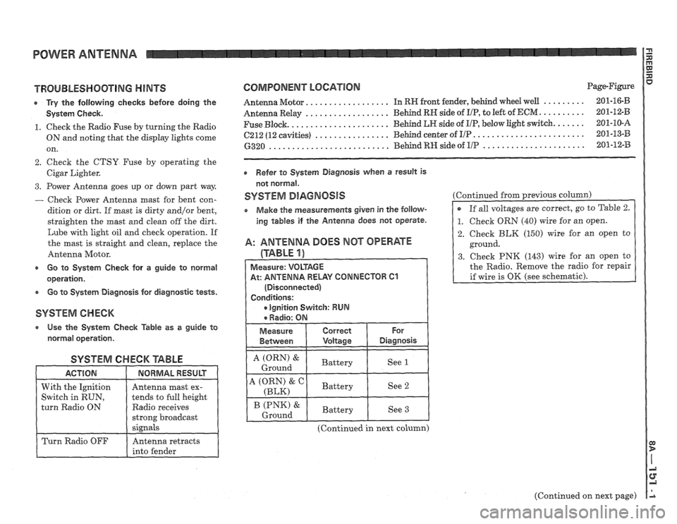
POWER ANTENNA
TROUBLESHOOTING HINTS
r Try the following checks before doing the
System Check.
1. Check the Radio Fuse by turning the Radio
ON and noting that the display lights come
on.
2. Check the CTSY Fuse by operating the
Cigar Lighter.
3. Power Antenna goes up or down part way
- Check Power Antenna mast for bent con-
dition or dirt. If
mast is dirty and/or bent,
straighten the mast and clean off the dirt.
Lube with light oil and check operation. If
the mast is straight and clean, replace the
Antenna Motor.
c Go to System Check for a guide to normal
operation.
e Go to System Diagnosis for diagnostic tests.
SYSTEM CHECK
a Use the System Check Table as a guide to
normal operation.
SYSTEM CHECK '6ABLE
Radio receives
COMPONENT LOCATION Page-Figure
................. ......... Antenna Motor. In RW front fender, behind wheel well 201-16-B
.................. .......... Antenna Relay Behind RN side of I/P, to
left of ECM 201-12-B
..................... ...... Fuse Block. Behind LR side
of UP, below light switch. 201-10-A
........................ ................ 6212 (12 cavities) Behind center of I/P 201-13-B
...................... .......................... 6320 Behind RH side of IIP 201-12-33
Refer to System Diagnosis when a result is
not normal.
SYSTEM DlAGNOSlS
o Make the measurements given in the follow-
ing tables if the Antenna does not operate.
A: ANTENNA DOES MOT OPERATE
(TABLE 1)
At: ANTENNA RELAY CONNECTOR 61
(Continued in next column) Continued
from previous
column)
2. Check BLK (150) wire for an open to
ground.
3. Check PNK (143) wire for an open to
the Radio. Remove the radio for repair
(Continued on next page)