1988 PONTIAC FIERO oil
[x] Cancel search: oilPage 1289 of 1825
MULTI-PORT FUEL INJECTION: V8 VIN 8 It
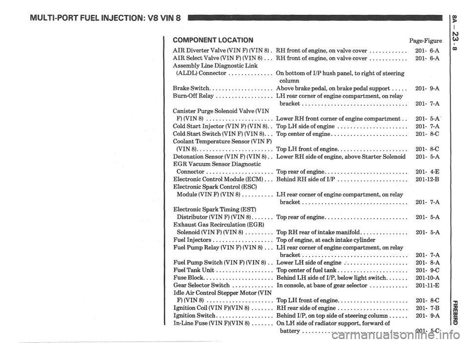
COMPONENT LOCATION Page-Figure
. ............ AIR Diverter Valve (VIN F) (VIN 8)
RN front of engine. on valve cover 201- 6-A
............ AIR Select Valve (VIN F) (VIN 8) ... RW front of engine. on valve cover 201- 6-A
Assembly Line Diagnostic Link
(ALDL) Connector
.............. On bottom of I/P hush panel. to right of steering
column
..... Brake Switch .................... Above brake pedal. on brake pedal support 201- 9-A
Burn-Off Relay
.................. LH rear corner of engine compartment. on relay
bracket
................................. 201- 7-A
Canister Purge Solenoid Valve (VIN
.. F) (VIN 8) ..................... Lower RH front corner of engine compartment 201- 5-A'
.. ...................... Cold Start Injector (VIN F) (VIN 8) Top LH side of engine 201- 7-A
........................ Cold Start Switch (VIN F) (VIN 8) ... Top center of engine 201- 8-6
Coolant Temperature Sensor (VIN F)
...................... (VIN 8) ........................ Top LN front of engine 201- 8-C
Detonation Sensor (VIN F) (VIN 8)
. . Lower RN side of engine. above Starter Solenoid 201- 5-A
EGR Vacuum Sensor Diagnostic
.......................... Connector ..................... Top rear of engine 201- 4-E
...................... Electronic Control Module (ECM) ... Behind RH side of IIP 201-12-B
Electronic Spark Control (ESC)
Module (VIN F) (VIN 8)
.......... LH rear corner of engine compartment. on relay
bracket
................................. 201- 7-A
Electronic Spark Timing (EST)
.......................... Distributor (VIN F) (VIN 8) ....... Top rear of engine 201- 5-A
Exhaust Gas Recirculation (EGR)
............... Solenoid (VIN F) (VIN 8) ......... Top RN rear of intake manifold 201- 5-A
Fuel Injectors
................... Top of engine. at each intake cylinder
Fuel Pump Relay (VIN F) (VIN 8)
... LH rear corner of engine compartment. on relay
bracket
................................. 201- 7-A
.. ................... Fuel Pump Switch (VIN F) (VIN 8)
Lower LH side of engine : 201- 8-A
...................... Fuel Tank Unit .................. Top center of fuel tank 201- 9-C
....... Fuse Block ...................... Behind LH side of IIP. below light switch 201-10-A
............ Gear Selector Switch ............. In console. at base of gear selector 201-11-E
Idle Air Control Stepper Motor (VIN
...................... F) (VIN 8) ..................... Top LN front of engine 201- 8-C
...................... Ignition Coil (VIN F)(VIN 8) ....... RH rear side of engine 201- 7-B
...... Ignition Switch .................. Behind IIP. on top side of steering column 201- 9-A
In-Line Fuse (VIN F)(VIN 8) ....... On LH side of radiator support. forward of
battery
................................. 201- 5-C
Page 1320 of 1825
VEHICLE SPEED SENSOR
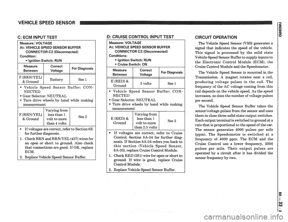
C: ECM INPUT TEST
At: VEHICLE SPEED SENSOR BUFFER
CONNECTOR
62 (Disconnected)
Gear Selector: NEUTRAL
1. Check BRN and
BRNIYEL (437) wires for
an open or short to ground. Also check
that connections are good. If
OK, replace
1 2. Replace Vehicle Speed Sensor Buffer.
At: VEHICLE SPEED SENSOR BUFFER
CONNECTOR
C2 (Disconnected)
Gear Selector: NEUTRAL
nosis. If Section 8A-34 refers you back to
this section (Vehicle Speed Sensor,
8A-33), replace Cruise Control Module.
1. Check RED (381) wire for open or short to
ground. If wire is good, replace Cruise
Control Module.
D: CRUISE CONTROL lNPUT TEST CIRCUIT OPERATION
The Vehicle Speed Sensor (VSS) generates a
signal that indicates the speed of the vehicle.
This signal is processed by the solid state
Vehicle Speed Sensor Buffer to supply inputs to
the Electronic Control Module (ECM), the
Cruise Control Module
and the Speedometer.
The Vehicle Speed Sensor is mounted in the
Transmission.
A magnet rotates near a coil,
producing voltage pulses in the coil. The
frequency of the AC voltage coming from this
coil depends on the vehicle speed. As the speed
increases, so does the number of voltage pulses
per second.
The Vehicle Speed Sensor Buffer takes the
sensorlvoltage pulses from the sensor and uses
them to close three solid state output switches.
Each output terminal is switched to ground at a
rate that is proportional to the speed of the car.
The sensor generates 4000 pulses per mile
(ppm). The Speedometer is switched at
a
frequency of 4000 ppm. The ECM and the
Cruise Control use a lower frequency, 2000
pulses per mile. Their output pulses are
operated by a circuit after it has divided the
sensor frequency by two.
Page 1327 of 1825
CRUISE CONTROL
(Continued from previous page)
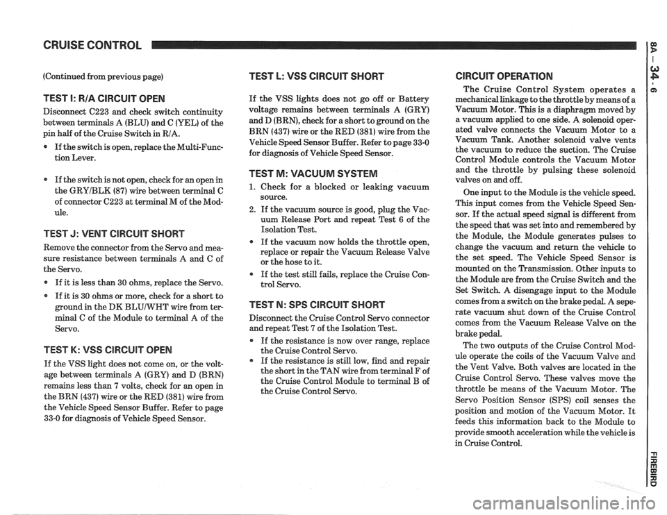
TEST I: RIA CIRCUIT OPEN
Disconnect C223 and check switch continuity
between terminals A (BLU) and C (YEL) of the
pin half of the Cruise Switch in RIA.
0 If the switch is open, replace the Multi-Func-
tion Lever.
If the switch is not open, check for an open in
the
GRYIBLK (87) wire between terminal C
of connector C223 at terminal M of the Mod-
ule.
TEST J: VENT CIRCUIT SHORT
Remove the connector from the Servo and mea-
sure resistance between terminals
A and C of
the Servo.
If it is less than 30 ohms, replace the Servo.
If it is 30 ohms or more, check for a short to
ground in the DK
BLUIWHT wire from ter-
minal C of the Module to terminal A of the
Servo.
TEST K: VSS ClRCUlT OPEN
If the VSS light does not come on, or the volt-
age between terminals A (GRY) and D (BRN)
remains less than 7 volts, check for an open in
the BRN (437) wire or the RED (381) wire from
the Vehicle Speed Sensor Buffer. Refer to page
33-0 for diagnosis of Vehicle Speed Sensor.
TEST L: VSS CIRCUIT SHORT
If the VSS lights does not go off or Battery
voltage remains between ter
and D
(BRN), check for a short to ground on the
BRN (437) wire or the RED (381) wire from the
Vehicle Speed Sensor Buffer. Refer to page 33-0
for diagnosis of Vehicle Speed Sensor.
TEST M: VACUUM SYSTEM
1. Check for a blocked or leaking vacuum
source.
2. If the vacuum source is good, plug the Vac-
uum Release Port and repeat Test
6 of the
Isolation Test.
If the vacuum now holds the throttle open,
replace or repair the Vacuum Release Valve
or the hose to it.
If the test still fails, replace the Cruise Con-
trol Servo.
TEST N: SPS CIRCUIT SHORT
Disconnect the Cruise Control Servo connector
and repeat Test 7 of the Isolation Test.
If the resistance is now over range, replace
the Cruise Control Servo.
If the resistance is still low, find and repair
the short in the TAN wire from terminal F of
the Cruise Control Module to terminal B of
the Cruise Control Servo.
ClRCUlT OPERATION
The Cruise Control System operates a
mechanical linkage to the throttle by means of a
Vacuum Motor. This is a diaphragm moved by
a vacuum applied to one side. A solenoid oper-
ated valve connects the Vacuum Motor to a
Vacuum Tank. Another solenoid valve vents
the vacuum to reduce the suction. The Cruise
Control Module controls the Vacuum Motor
and the throttle by pulsing these solenoid
valves on and off.
One input to the Module is the vehicle speed.
This input comes from the Vehicle Speed Sen-
sor. If the actual speed signal is different from
the speed that was set into and remembered by
the Module, the Module generates pulses to
change the vacuum and return the vehicle to
the set speed. The Vehicle Speed Sensor is
mounted on the Transmission. Other inputs to
the Module are from the Cruise Switch and the
Set Switch. A disengage input to the Module
comes from a switch on the brake pedal. A
sepe-
rate vacuum shut down of the Cruise Control
comes from the Vacuum Release Valve on the
brake pedal.
The two outputs of the Cruise Control Mod-
ule operate the coils of the Vacuum Valve and
the Vent Valve. Both valves are located in the
Cruise Control Servo. These valves move the
throttle be means of the Vacuum Motor. The
Servo Position Sensor
(SPS) coil senses the
position and motion of the Vacuum Motor. It
feeds this information back to the Module to
provide smooth acceleration while the vehicle is
in Cruise Control.
Page 1331 of 1825
HORNS --
(Continued from previous page)
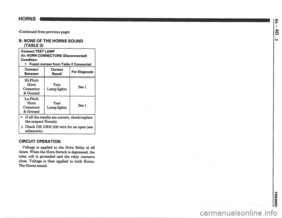
B: NONE OF THE HORNS SOUND
(TABLE
3)
t: HORN CONNECTORS (Disconnected)
. Check DK GRN (29) wire for an open (see
GlRCUlT OPERATION
Voltage is applied to the Horn Relay at all
times. When the Horn Switch is depressed, the
relay coil is grounded and the relay contacts
close. Voltage is then applied to both Horns.
The Horns sound.
Page 1353 of 1825
AIR CONDITIONING: BLOWER CONTROLS
C60, MANUAL
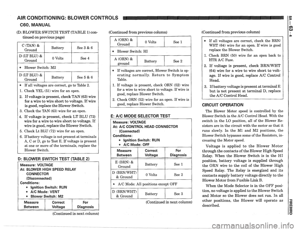
(D: BLOWER SWITCH TEST (TABLE 1) con- (Continued
from previous column) (Continued
from previous column)
tinued on previous page)
D: BEClVVER SWITCH TEST (TABLE 2)
(TAN) '
Ground
D (LT BLU) &
Ground
Between I Voltage I Diagnosis
Battery
Volts
Measure: VOLTAGE
At:
BLIWEW HIGH SPEED RELAY
CONNECTOR
(Disconnected)
, Conditions:
ignition Switch: RUM
A/C Mode: VENT
' @ Blower Switch: M2
See 3 & 6
See 4
Blower Switch: M2
~easure I Correct
E: AIC MODE SELECTOR TEST
At: A/C CONTROL HEAD CONNECTOR
(Connected)
Conditions:
lgnition Switch: RUM
Ground 0
Volts
D (LT BLU) 8
Ground
For
A (ORN) &
ground
Between I Voltage I Diagnosis
If all voltages are correct, go to Table 2.
1. Check YEL (51) wire for an open.
2. If voltage is present, check TAN (63) wire
for a wire to wire short to voltage. If wire
is good, replace the Blower Switch.
3. Check the TAN (63) wire for an open.
4. If voltage is present, check LT BLU (72)
wire for a wire to wire short to voltage.
If
wire is good, replace the Blower Switch.
5. Check Lt BLU (72) wire for an open.
6. If battery voltage is not present at terminals
A,
G or D, go to Test E. If voltage is present
at one or more of the terminals, replace the
Blower Switch.
Battery
e A/c Mode: OFF
I (BRN) & I Battery
Ground I see 1 /
If voltages are correct, Blower Switch is op-
erating normally. Return to Symptom
Table.
1. If voltage is present, check ORN (52) wire
for a wire to wire short to voltage. If wire is
good, replace Blower Switch.
2. Check ORN
(52) wire for an open. If wire is
good, replace Blower Switch.
Battery
See 5
& 6
Measure I Correct
See 2
For
I e AIC Mode: All positions except OFF I
D (BRNNHT)
& Ground
I (BRNIWHT) I Battery & Ground I see 3 /
(Continued in next column)
Volts
@ If all voltages are correct, check the BRNI
WNT (64) wire for an open. If wire is good
replace the Blower Switch.
1. Check BRN (50) wire for an open back to
HTR
A/C Fuse.
2. If voltage is present, check BRNIWNT
(64) wire for a wire to wire short to volt-
age. If wire is good, replace
A/C Control
Head.
3. If battery voltage is present at terminal E
but is not present at terminal D, replace
the
AIC Control Head.
See 2 The
Blower Motor speed is controlled by the
Blower Switch in the
AIC Control Head. With the
switch in the LO position, all of the Blower Re-
sistors are in the circuit with the motor so that it
runs slowly. In the
M1 and M2 positions, the
Blower Switch bypasses some of the Resistors, in-
creasing the Motor speed.
Voltage is applied to the Blower Motor
through the contacts of the Blower Nigh Speed
Relay. When the Blower Switch is in the
HI
position, battery voltage is supplied through
the ORN wire to the coil of the Blower High
Speed Relay. The Relay is energized and its
contacts supply battery voltage directly to the
Blower Motor from Fusible
Link B.
When the Mode Selector is in the OFF posi-
tion, no voltage is applied to the Blower Switch
and Motor so the Blower does not run. In all
other positions, the Blower will operate as
described.
(Continued in next column)
Page 1375 of 1825
AIR CONDITIONING: BLOWER CONTROLS
C67, ELECTRONIC
(Continued from previous page)
GRNIBLK (990) wire. If wire is good, do
Test
E.
5. Check for open in BRNNHT (64) wire. If
wire is good, do Test
E.
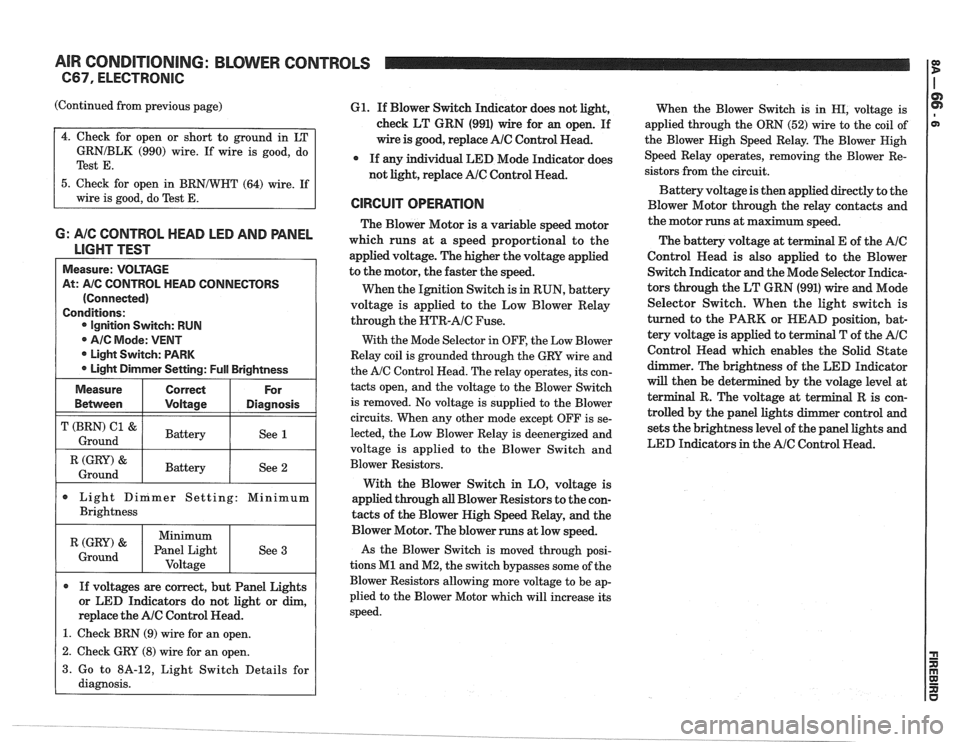
6: A/C CONTROL HEAD LED AND PANEL
LIGHT TEST
Measure: VOLTAGE
At:
A/C CONTROL HEAD CONNECTORS
(Connected)
Conditions: Ignition Switch: RUN
@ AIC Mode: VENT
* Light Switch: PARK
Light Dimmer Setting:
Full Brightness
I (GRY) & I Battery / See 2 1 Ground
Measure
Bemeen
T (BRN) C1 &
Ground
Light Dinimer Setting: Minimum
Brightness
Correct
Voltage
Battery
If voltages are correct, but Panel Lights
or LED Indicators do not light or dim,
replace the
AlC Control Head.
1. Check BRN (9) wire for an open.
For
Diagnosis
See 1
(GRY) '
Ground
61. If Blower Switch Indicator does not light,
check LT GRN (991) wire for an open. If
wire is good, replace
AlC Control Read.
* If any individual LED Mode Indicator does
not light, replace
AlC Control Head.
CIRCUIT OPERATION
The Blower Motor is a variable speed motor
which runs at a speed proportional to the
applied voltage. The higher the voltage applied
to the motor, the faster the speed.
When the Ignition Switch is
in RUN, battery
voltage is applied to the Low Blower Relay
through the
NTR-AIC Fuse.
With the Mode Selector in OFF, the Low Blower
Relay coil is grounded through the GRY wire and
the
A/C Control Head. The relay operates, its con-
tacts open, and the voltage to the Blower Switch
is removed. No voltage is supplied to the Blower
circuits. When any other mode except OFF is se-
lected, the Low Blower Relay is deenergized and
voltage is applied to the Blower Switch and
Blower Resistors.
With the Blower Switch in LO, voltage is
applied through
all Blower Resistors to the con-
tacts of the Blower High Speed Relay, and the
Minimum
Panel Light Voltage
- -
Blower Motor. The blower runs at low speed.
As the Blower Switch is moved through posi-
tions
M1 and M2, the switch bypasses some of the
Blower Resistors allowing more voltage to be ap-
plied to the Blower Motor which will increase its
speed.
See
3
When
the Blower Switch is in HI, voltage is
applied through the ORN (52) wire to the coil of
the Blower Nigh Speed Relay. The Blower Nigh
Speed Relay operates, removing the Blower Re-
sistors from the circuit.
Battery voltage is then applied directly to the
Blower Motor through the relay contacts and
the motor runs at maximum speed.
The battery voltage at
t
Control Read is also applied to the Blower
Switch Indicator and the Mode Selector Indica-
tors through the LT GRN (991) wire and Mode
Selector Switch. When the light switch is
turned to the PARK or HEAD position, bat-
tery voltage is applied to terminal T of the
AIC
Control Head which enables the Solid State
dimmer. The brightness of the LED Indicator
will then be det
terminal R. The volt
trolled by the panel
sets the brightness level of the panel lights and
LED Indicators in the
AIC Control Head.
1 2. Check GRY (8) wire for an open. I
3. Go to 8A-12, Light Switch Details for
diagnosis.
Page 1403 of 1825
INSTRUMENT PANEL: GAGES CLUSTER I e
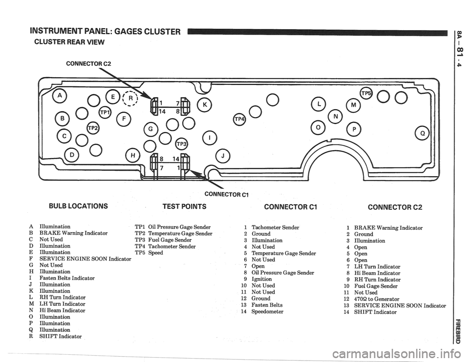
CLUSTER REAR VIEW
CONNECTOR 62
-
BULB LOCATIONS
CONNECTOR Cl
TEST POINTS CONNECTOR Cl
A Illumination TP1 Oil Pressure Gage Sender 1
B BRAKE Warning Indicator TP2 Temperature Gage Sender 2
C Not Used TP3 Fuel Gage Sender 3
D Illumination TP4 Tachometer Sender 4
E Illumination TP5 Speed 5
F SERVICE ENGINE SOON Indicator
6
G Not Used 7
H Illumination 8
I Fasten Belts Indicator 9
J Illumination 10
K Illumination 11
L RH Turn Indicator 12
M LH Turn Indicator 13
N Hi Beam Indicator 14
O Illumination
P Illumination
Q Illumination
R SHIFT Indicator Tachometer Sender
Ground
Illumination
Not Used
Temperature Gage Sender
Not Used
Open
Oil Pressure Gage Sender
Ignition
Not Used
Not Used
Ground
Fasten Belts
Speedometer
CONNECTOR 62
1 BRAKE Warning Indicator
2 Ground
3 Illumination
4 Open
5 Open
6 Open
7 LH Turn Indicator
8 Hi Beam Indicator
9 RH Turn Indicator
10 Fuel Gage Sender
11 Not Used
12
470R to Generator
13 SERVICE ENGINE SOON Indicator
14 SHIFT Indicator
Page 1404 of 1825
INSTRUMENT PANEL: GAGES CLUSTER
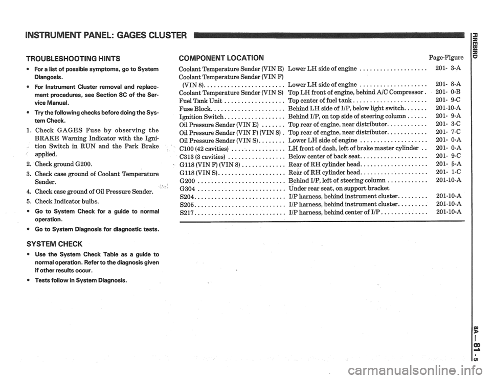
TROUBLESHOOTING HINTS COMPONENT LOCATION Page-Figure
* For a list of possible symptoms, go to System Coolant Temperature Sender (VIN E) Lower LH side of engine ....................
Diangosis. Coolant Temperature Sender (VIN F)
....................... .................... * For Instrument Cluster removal and replace- (VIN 8). Lower
LH side of engine
ment procedures, see Section 8C of the Ser- Coolant Temperature Sender (VIN S) Top LN front of engine, behind A/C Compressor.
.................. ..................... vice Manual. Fuel Tank Unit Top center of fuel tank.
..................... ...... * Try the following checks before doing the Sys- Fuse Block. Behind
LH side of IIP, below light switch.
................. tem Check. Ignition Switch. Behind IIP, on
top side of steering co
....... ........... Oil Pressure Sender (VIN E) Top rear of engine, near distributor. 1. Check GAGES Fuse by observing the . ........... Oil Pressure Sender (VIN F) (VIN 8) Top
rear of engine, near distributor.
BRAKE Warning Indicator with the Igni- Oil Pressure Sender (VIN S) ........ Lower LN side of engine .................... tion Switch in RUN and the Park Brake ................ .. el00 (42 cavities) LN
front of dash, left of brake master cylinder
applied.
................. C313 (3 cavities) Below
center of back seat. ...................
2. Check ground 6200. . 6118 (VIN F) (VIN 8) ............. Rear of RN cylinder head. ...................
.................... ................... 3. Check case ground of Coolant Temperature 6118
(VIN S) Rear
of RH cylinder head.
.......................... ............ Sender. 6200 Behind I/P, left of steering column ' h .......................... 4. Check case ground of Oil Pressure Sender. 6304 Under rear seat,
on support bracket
.......................... S204. IIP harness, behind instrument cluster. ........ 5. Check Indicator bulbs. .......................... ........ S205. I/P harness, behind instrument cluster. * Go to System Check for a guide to normal .......................... S217. I/P harness, behind center of IIP .............. operation.
* Go to Systern Diagnosis for diagnostic tests.
SYSTEM CHECK
* Use the System Check Table as a guide to
normal operation. Refer to the diagnosis given
if other results occur.
* Tests follow in System Diagnosis.