1988 PONTIAC FIERO oil
[x] Cancel search: oilPage 1163 of 1825
7C-6 CLUTCH
6. Clutch master cylinder push rod to clutch pedal.
7. Install brake switch.
8. Install hush panel.
9. Install steering column trim cover.
10. Install clutch reservoir to bracket.
1 1. Hoist vehicle.
12. Pilot slave cylinder into clutch fork.
NOTICE: With a new system, the slave cylinder
contains a shipping strap that pre-positions the
push rod for installation, and also provides a
bearing insert.
Follojving installation of the slave
cylinder, the first actuation of the clutch pedal will
break the shipping strap and give
normal system
operation.
13. Install slave cylinder and heat shield to bell
housing.
14.
Lojver vehicle.
15. Connect negative battery cable.
CLUTCH ASSEMBLY
Removal
1. Remove the transmission as outlined in
transmission section.
2. Remove the slave cylinder heat shield and slave
cylinder
from flywheel housing.
3. Reniove the flywheel housing.
4. Slide clutch fork from ball stud and remove fork
from dust boot. Ball stud is threaded into clutch
housing and is easily replaced, if necessary.
5. Install Tool 5-33169 to support the clutch
assen~bly during removal. Look for mark or white
painted letter on clutch cover and
"X" mark on
flywheel. If
"Xu or letter is not evident, mark
flywheel and clutch cover for indexing purposes
during installation.
6. Loosen clutch-to-flywheel attaching bolts evenly
1 turn at a time until spring pressure is released.
7. Remove clutch and pressure plate assembly.
lnspection
Inspect the flywheel for cracks, heat checking or
other defects. Replace or repair as required.
Installation
Pressure plate and flywheel face, (They should be
free of oil, grease, metal deposits or burned spots.)
Installation
1. Position clutch disc and pressure plate in relative
installed position and support them with
alignment Tool J-33169 or a drive gear.
The driven disc is installed with the damper
springs to the transmission. The flywheel side is
marked.
2. Turn clutch assembly until "X" mark or white
painted letter on cover lines up with
"X" mark on flywheel,
then align cover bolt holes to nearest
flywheel holes.
3. Install a bolt in every hole and tighten down
evenly and gradually until tight to avoid possible
clutch distortion. (Cover loads are as high as
1- 1/4 tons).
4. Remove the pilot tool.
5. Unhook clutch fork and lubricate ball socket and
fork fingers at release bearing end with a high
melting point grease such as graphite and
reinstall fork on ball stud.
6. Lubricate recess on inside of release bearing
collar and the clutch fork groove with light coat
of graphite grease. Refer to Figure 7C-6.
7. Install the clutch fork and dust boot into clutch
housing and install release bearing to fork, then
install flywheel housing.
8. Install the transmission as outlined in
transmission section.
9. Install the clutch slave cylinder and bracket.
CLUTCH PEDAL
Removal
Disconnect the negative cable at battery.
Remove the steering column trim cover.
Remove the hush panel from under dash.
If equipped, disconnect cruise control switch at
clutch pedal.
Disconnect the neutral start switch at clutch
pedal.
Renlove the turn signal and hazard flasher
mounting bracket attaching screws.
Disconnect the clutch master cylinder push rod
from pedal.
Remove the nut from clutch pedal pivot bolt. Pull
bolt out far enough for pedal removal.
Inspection
Clean and inspect all components and replace as
necessary. Do not clean bushings with a cleaning
solvent, simply wipe with a clean cloth.
Relubricate all bushings and moving parts.
Installation
1. Reverse the removal procedure.
PILOT BEARING (FIGURE 7C-7)
Replacement
The clutch pilot bearing is an oil impregnated type
bearing pressed into the crankshaft. This bearing requires
attention when the clutch is removed from the vehicle, at
which time it should be cleaned and inspected for exces-
sive wear or damage and should be replaced if necessary.
To remove, install Tool
J 23907 and remove bearing
from crankshaft, as shown in Figure
7C-7. In replacing
this bearing, use Tool
J 1522. Place bearing on pilot of
tool with radius in bore of bearing next to shoulder on tool
and drive into crankshaft. Lubricate with several drops of
machine oil.
Page 1167 of 1825
Page
Air Conditioning
Air Delivery
Electronic
.................... 68-0
Manual
....................... 65-0
Blower Controls
Electronic
.................... 66-0
Manual
....................... 63-0
Compressor Controls Electronic
.................... 67-0
Manual
....................... 64-0
................... System Check 62-0
Alarms (Audible)
Chime
......................... 77-0
Antenna(Power) ................... 151-0
Brakes
................. Warning System 41-0
................... Charging system 30-7
...................... Cigar Lighter 114-0
Circuit Breaker Details
PWR ACC Circuit
.......... Breaker 10.1.10.3.10.5.1 1.3
WDO Circuit Breaker
10.1. 10.3. 10.5. 11-4
.......... Component Location Views 201-0
Connectors (Harness Connector Faces) 202-0
el00 .......................... 202-0
............... Junction Block ((2238) 202-2
Coolant Fan
....................... 31-0
Cruise Control
..................... 34-0
Defogger
......................... 61-0
Digital Clock
...................... 150-0
Displays Digital Cluster
.................. 82-0
Coolant Temperature
........... 82-2
Page
......................... Fuel 82-3
................... Oil Pressure 82-2
.................. Speedometer 82-3
................. Door Locks (Power) 130-0
...... Driver Information Center (DIC) 86-0
Engines
... Multi-Port Fuel Injection (VIN S) 20-0
.... Multi-Port Fuel Injection (VIN 8) 23-0
.... Throttle
Body Injection (VIN E) 22-0
...... Tuned
Port Injection (VIN F) 21-0
................. Fuse Block Details 11-0
Fuse Details
........... INST LP 10.0.10.2.10.4.1 1.1
.............. TAIL 10.0.10.2.10.4.1 1.2
................ CRANK 10.0.10.2.1 0.4
.............. CTSY 10~0.10.2.10.4.1 1.2
......... STOP HAZ 10.1.10.3.10.5.1 1.3
............ RADIO 10.1.10.3.10.5.1 1.4
............ WIPER 10.1.10.3.10.5.1 1.4
.................... HATCH 10.2.1 0.4
........... HTR AlC 10.1.10.3.10.5.1 1.4
........... CIH.FAN 10.1.10.3.10.5.1 1.4
......... TURN BIU 10.1.10.3.10.5.1 1.4
............ GAGES 10.1.10.3.10.5.1 1.4
ECM-IGN
(V6 VIN S. V8 VIN F.
........ V8 VIN 8. V8 VIN E) 10.1.1 1.7
............ INJ 1 (V6 VIN S) 10.1.1 1.10
......... FPIINJ 2 (V6 VIN S) 10.1.1 1.10
... INJ 1 (V8 VIN F. V8 VIN 8) 10.3.1 1.11
FPIINJ 2 (V8 VIN F. V8 VIN 8) 10.3.1 1.11
............ CLSTR 10.1.10.3.10.5.1 1.13
............. FPIINJ 2 (V8 VIN E) 11-12
Page
Gages
................... Gages Cluster 81-0
........... Coolant Temperature 81-2
......................... Fuel 81-3
................... Oil Pressure 81-2
.................. Speedometer 81-3
................ Ground Distribution 14-0
Harness Routing Views
............. 203-0
........................... Heater 60-0
............................ Horns 40-0
Indicators
.................. Digital Cluster 82-0
................ Brake Warning 82-4
.................. Fasten Belts 82-1
...................... Hi Beam 82-1
...................... Security 82-1
............ Service Engine Soon 82-4
......................... Shift 82-5
......................... Turn 82-1
................... Gages Cluster 81-0
................ Brake Warning 81-0
.................. Fasten Belts 81-0
...................... Hi Beam 81-0
............ Service Engine Soon 81-0
......................... Shift 81-1
......................... Turn 81-0
Instrument Panel
Digital Cluster
.................. 82-0
Gages Cluster
................... 81-0
............ Interior Lights Dimming 117-0
...................... Introduction 2-0
Lights (Exterior)
........................ Back Up 112-0
...................... Fog 100.3,10 3.0
Page 1170 of 1825
These schematics break the entire electrical
system down into individual circuits. You are
not distracted by wiring which is not part of
the circuit you're working on.
It is important to realize that no attempt is
made on the schematic to represent compo-
nents and wiring as they physically appear on
the car. For example, a 4-foot length of wire is
treated no differently in a schematic from one
which is only a few inches long. The number of
cavities for each connector is listed in the Com-
ponent Location List. Similarly, switches and
other components are shown as simply as pos-
sible, with regard to function only.
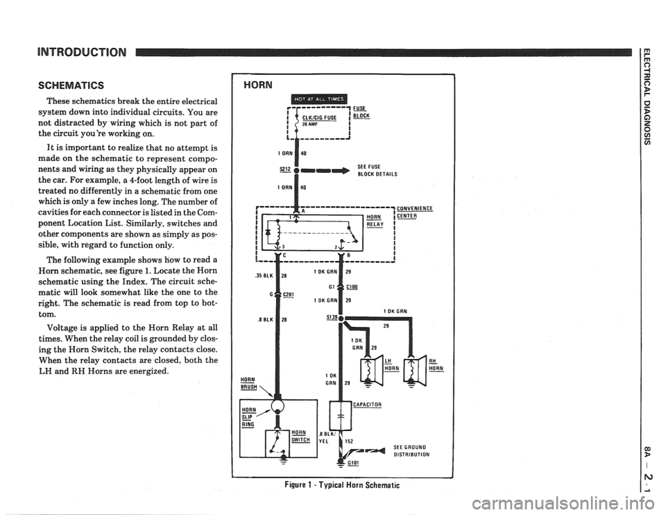
The following example shows how to read a
Worn schematic, see figure
1. Locate the Horn
schematic using the Index. The circuit sche-
matic will look somewhat like the one to the
right. The schematic is read from top to bot-
tom.
Voltage is applied to the Horn Relay at all
times. When the relay coil is grounded by clos-
ing the Horn Switch, the relay contacts close.
When the relay contacts are closed, both the
LH and
RH Horns are energized.
1 HORN
SEE FUSE
I BLOCK DETAILS
Figure 1 - Typical Horn Schematic
Page 1179 of 1825
SYMBOLS
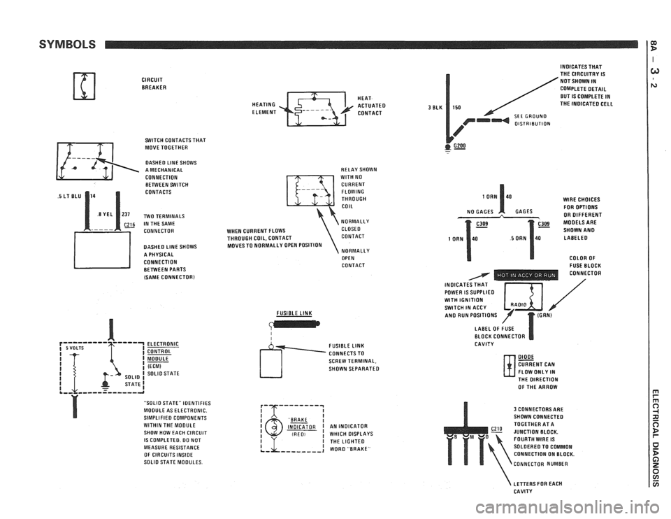
CIRCUIT BREAKER
SWITCH CONTACTS THAT
MOVE TOGETHER
DASHED LlNE SHOWS
A MECHANICAL
CONNECTION BETWEEN SWITCH
CONTACTS
~26 IN THE SAME
CONNECTOR
DASHED
LlNE SHOWS
A PHYSICAL
CONNECTION BETWEEN PARTS
(SAME
CONNECTORl
ELECTRONIC
CONTROL
MODULE
(ECM) SOLlO STATE
STATE1 .,, ,,,--=----,-a
"SOLIO STATE" IDENTIFIES
MODULE AS ELECTRONIC.
SIMPLIFIED COMPONENTS
WITHIN THE MOOULE
SHOW HOW EACH CIRCUIT
IS COMPLETED. DO NOT
MEASURE RESISTANCE
OF CIRCUITS
INSIDE SOLlO STATE MODULES. HEAT
HEATING
ACTUATED ELEMENT CONTACT
RELAY SHOWN
WlTH NO
CURRENT FLOWING
THROUGH
COIL
NORMALLY
WHEN CURRENT FLOWS CLOSE0
THROUGH COIL, CONTACT CONTACT
MOVES TO NORMALLY OPEN POSITION
NORMALLY
OPEN
CONTACT
FUSIBLE
LINK
I I
SCREW TERMINAL,
SHOWN SEPARATED
I BAAKE I INDICATOR I AN INDICATOR (RED, ! WHICH DISPLAYS
3 BLK
INDICATES THAT
THE CIRCUITRY IS
NOT SHOWN IN
COMPLETE DETAIL
BUT
IS COMPLETE IN
150 THE INOICATED CELL
SEE GROUND OlSTRlBUTlON
GZOO . -
WlRE CHOICES
FOR OPTIONS
GAGES OR DIFFERENT
SHOWN
AN0 LABELED
COLOR OF
- FUSE BLOCK - - - - - - - . . CONNECTOR
INOICAT / POWER IS SUPPLIED I $ I / WlTH IGNITION SWITCH IN ACCY /' AN0 RUN POSITIONS
LABEL OF FUSE
BLOCK CONNECTOR
CAVITY
DIODE CURRENT CAN
FLOW ONLY IN
N- THE DIRECTION
OF THE ARROW
3 CONNECTORS ARE
SHOWN CONNECTED
TOGETHER AT A
JUNCTION BLOCK.
FOURTH
WIRE IS
SOLDERED TO COMMON
CONNECTION ON BLOCK.
CONNECTOR NUMBER
LETTERS FOR EACH
CAVITY
Page 1211 of 1825
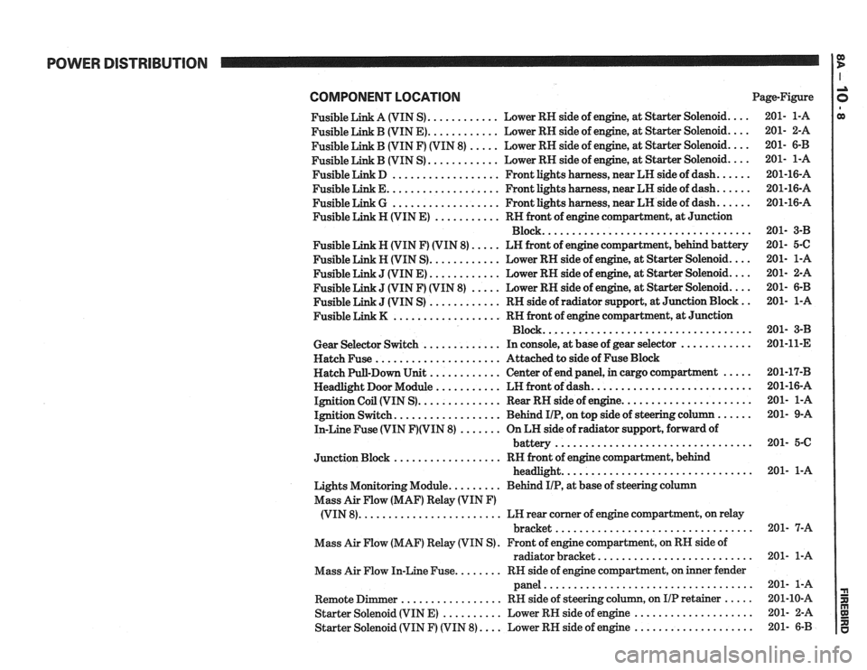
POWER DISTRIBUTION
COMPONENT LOCATlON Page-Figure
Fusible Link A (VIN S)
............ Lower RH side of engine. at Starter Solenoid ....
Fusible Link B (VIN E) ............ Lower RH side of engine. at Starter Solenoid ....
Fusible Link B (VIN F) (VIN 8) ..... Lower RH side of engine. at Starter Solenoid ....
............ Fusible Link B (VIN S) Lower
RH side of engine. at Starter Solenoid ....
Fusible Link D .................. Front lights harness. near LH side of dash ......
Fusible Link E ................... Front lights harness. near LH side of dash ......
Fusible Link G .................. Front lights harness. near LH side of dash ......
Fusible Link H (VIN E) ........... RH front of engine compartment. at Junction
Block
...................................
Fusible Link N (VIN F) (VIN 8) ..... LN front of engine compartment. behind battery
Fusible Link H (VIN S)
............ Lower RH side of engine. at Starter Solenoid ....
J (VIN E) ............ Lower RH side of engine, at Starter Solenoid ....
J (VIN F) (VIN 8) ..... Lower RH side of engine, at Starter Solenoid ....
J (VIN S) ............ RH side of radiator support. at Junction Block ..
.................. Fusible Link K RN front of engine compartment. at Junction
Block
...................................
Gear Selector Switch ............. In console, at base of gear selector ............
Hatch Fuse ..................... Attached to side of Fuse Block
Hatch Pull-Down Unit
............ Center of end panel, in cargo compartment .....
Headlight Door Module ........... LH front of dash ...........................
Ignition Coil (VIN S) .............. Rear RH side of engine ......................
Ignition Switch .................. Behind IIP. on top side of steering column ......
In-Line Fuse (VIN F)(VIN 8) ....... On LH side of radiator support. forward of
................................. battery
.................. Junction Block RH front of engine compartment. behind
................................ headlight
Lights Monitoring Module
......... Behind IIP. at base of steering column
Mass Air Flow (MAF) Relay (VIN
F)
........................ (VIN 8) LH rear corner of engine compartment, on relay
................................. bracket
Mass Air Flow (MAF) Relay (VIN S)
. Front of engine compartment. on RH side of
radiator bracket
..........................
Mass Air Flow In-Line Fuse ........ RN side of engine compartment, on inner fender
panel
...................................
Remote Dimmer ................. RH side of steering column. on IIP retainer .....
Starter Solenoid (VIN E) .......... Lower RH side of engine ....................
Starter Solenoid (VIN F) (VIN 8) .... Lower RH side of engine ....................
Page 1250 of 1825
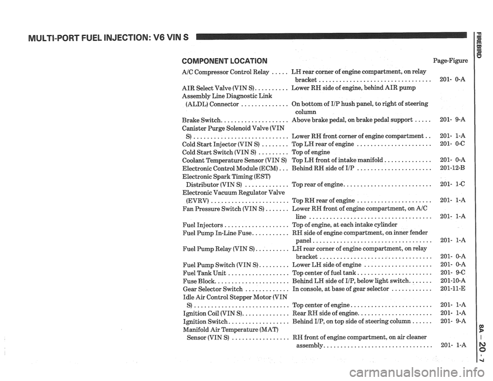
MULTI-PORT FUEL INJECTION: V6 VIN S
COMPONENT LOCATION
AIC Compressor Control Relay ..... LH rear corner of engine compartment, on relay
................................. bracket
AIR Select Valve (VIN S)
.......... Lower RN side of engine, behind AIR pump
Assembly Line Diagnostic Link
(ALDL) Connector
.............. On bottom of IIP hush panel, to right of steering
column
Brake Switch.
................... Above brake pedal, on brake pedal support .....
Canister Purge Solenoid Valve (VIN
............................ .. S) Lower RH front
corner of engine compartment
Cold Start Injector (VIN S)
........ Top LH rear of engine ......................
Cold Start Switch (VIN S) ......... Top of engine
Coolant Temperature Sensor (VIN S) Top LN front of intake manifold.
.............
Electronic Control Module (ECM) ... Behind RH side of IIP ......................
Electronic Spark Timing (EST)
......................... Distributor (VIN S) ............. Top rear of engine.
Electronic Vacuum Regulator Valve
(EVRV)
....................... TopRHrearofengine ......................
Fan Pressure Switch (VIN S) ....... Lower RH front of engine compartment, on AIC
line ....................................
Fuel Injectors ................... Top of engine, at each intake cylinder
Fuel Pump In-Line Fuse.
.......... RH side of engine compartment, on inner fender
panel
...................................
Fuel Pump Relay (VIN S) .......... LH rear corner of engine compartment, on relay
................................. bracket
Fuel Pump Switch (VIN S)
......... Lower LH side of engine ....................
Fuel Tank Unit .................. Top center of fuel tank ......................
Fuse Block. ..................... Behind LH side of IIP, below light switch. ......
Gear Selector Switch ............. In console, at base of gear selector ............
Idle Air Control Stepper Motor (VIN
S)
............................ Topcenterofengine ........................
Ignition Coil (VIN S). ............. Rear RH side of engine. .....................
Ignition Switch. ................. Behind IIP, on top side of steering column ......
Manifold Air Temperature (MAT)
................. Sensor (VIN S) RH front of engine compartment, on air cleaner
............................... assembly. Page-Figure
Page 1264 of 1825
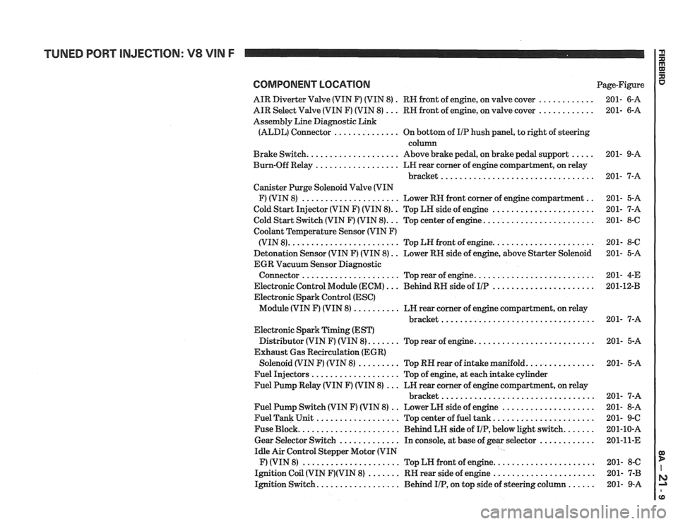
COMPONENT LOCATION Page-Figure
AIR Diverter Valve (VIN F) (VIN 8)
. RN front of engine, on valve cover ............ 201- 6-A
AIR Select Valve (VIN F) (VIN 8)
... RN front of engine, on valve cover ............ 201- 6-A
Assembly Line Diagnostic Link
(ALDL) Connector
.............. On bottom of IIP hush panel, to right of steering
column
Brake Switch.
................... Above brake pedal, on brake pedal support ..... 201- 9-A
Bum-Off Relay
.................. LN rear comer of engine compartment, on relay
bracket
................................. 201- 7-A
Canister Purge Solenoid Valve (VIN
F) (VIN 8)
..................... Lower RN front corner of engine compartment .. 201- 5-A
Cold Start Injector (VIN F) (VIN 8).
. Top LH side of engine ...................... 201- 7-A
.. ....................... Cold Start Switch (VIN F) (VIN 8). Top center of engine. 201- 8-6
Coolant
Temperature Sensor (VIN F)
..................... (VIN 8). ....................... Top LN front of engine. 201- 8-C
Detonation Sensor (VIN F) (VIN 8)
. . Lower RN side of engine, above Starter Solenoid 201- 5-A
EGR Vacuum Sensor Diagnostic
......................... Connector ..................... Top rear of engine. 201-
4-E
Electronic Control Module (ECM)
... Behind RN side of IIP ...................... 201-1243
Electronic Spark Control (ESC)
Module (VIN F) (VIN 8)
.......... LN rear corner of engine compartment, on relay
............................... bracket.. 201- 7-A
Electronic Spark Timing (EST)
Distributor (VIN
F) (VIN 8). ...... Top rear of engine. ......................... 201- 5-A
Exhaust Gas Recirculation (EGR)
Solenoid (VIN
F) (VIN 8) ......... Top RN rear of intake manifold. .............. 201- 5-A
Fuel Injectors
................... Top of engine, at each intake cylinder
Fuel Pump Relay (VIN
F) (VIN 8) ... LN rear corner of engine compartment, on relay
bracket
................................. 201- 7-A
Fuel Pump Switch (VIN
F) (VIN 8) .. Lower LN side of engine .................... 201- 8-A
Fuel Tank Unit
.................. Top center of fuel tank ...................... 201- 9-C
Fuse Block.
..................... Behind LH side of IIP, below light switch. ...... 201-10-A
Gear Selector Switch
............. In console, at base of gear selector ............ 201-11-E
Idle Air Control Stepper Motor (VIN
F) (VIN 8)
..................... Top LN front of engine. ..................... 201- 8-C
Ignition Coil (VIN
F)(VIN 8) ....... RN rear side of engine ...................... 201- 7-B
Ignition Switch.
................. Behind IIP, on top side of steering column ...... 201- 9-A
Page 1277 of 1825
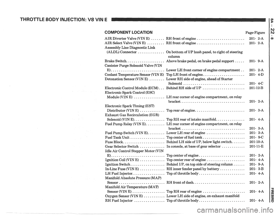
THROTTLE BODY INJECTION: V8 VIN E
COMPONENT LOCATION Page-Figure
AIR Diverter Valve (VIN E)
....... RH front of engine .........................
AIR Select Valve (VIN E) ......... RH front of engine .........................
Assembly Line Diagnostic Link
(ALDL) Connector
.............. On bottom of IIP hush panel, to right of steering
column
Brake Switch.
................... Above brake pedal, on brake pedal support .....
Canister Purge Solenoid Valve (VIN
E)
............................ Lower LH front corner of engine compartment ..
Coolant Temperature Sensor (VIN E) Top LH front of engine. .....................
Detonation Sensor (VIN E) ........ Lower RK side of engine, ahead of Starter
Solenoid
................................
Electronic Control Module (ECM) ... Behind RH side of IIP ......................
Electronic Spark Control (ESC)
Module (VIN E)
................ LH rear corner of engine compartment, on relay
................................. bracket
Electronic Spark Timing (EST)
Distributor (VIN E)
............. Top rear of engine. .........................
Exhaust Gas Recirculation (EGR)
Solenoid (VIN E).
............... Top RH rear of intake manifold. ..............
Fuel Pump Relay (VIN E). ......... LH rear corner of engine compartment, on relay
................................. bracket
Fuel Pump Switch (VIN E).
........ Lower LH rear of engine ....................
Fuel Tank Unit .................. Top center of fuel tank. .....................
Fuse Block. ..................... Behind LH side of IIP, below light switch. ......
Gear Selector Switch ............. In console, at base of gear selector ............
Idle Air Control Stepper Motor (VIN
E)
............................ Topcenterofengine ........................
Ignition Coil (VIN E) ............. Top center rear of engine ....................
Ignition Switch. ................. Behind IIP, on top side of steering column ......
In-Line Fuse (VIN E) ............. RW inner fender panel by battery .............
LW Fuel Injector. ................ Top of throttle body. .......................
Manifold Absolute Pressure (MAP)
Sensor
........................ RH front of dash. ..........................
Manifold Air Temperature (MAT)
Sensor (VIN
E) ................. Top RK rear of engine ......................
Oxygen Sensor (VIN E) ........... Lower LH side of engine, on exhaust manifold
RH Fuel Injector
................ Top of throttle body. .......................