1988 PONTIAC FIERO oil
[x] Cancel search: oilPage 1143 of 1825
Install or Conned
1. New seal using Tool J 21426.
2. Propeller shaft. (See Section 4A)
3. Lower vehicle.
4. Check transmission fluid level.
SPEEDOMETER DRIVEN GEAR
Remove or Disconnect
1. Raise vehicle.
2. Speedometer cable.
3. Lock plate and retaining bolt.
4. Pry gear fitting and shaft from housing.
5. O-ring from fitting.
Install or Connecl
1. Coat driven gear shaft and new O-ring with
transmission lubricant.
2. New O-ring.
3. Insert shaft.
4. Position fitting into extension housing.
5. Lock plate and retaining bolt.
6. Speedometer cable.
7. Lower vehicle.
TRANSMISSION
Figure 4
Disassemble
@ Exterior of the transmission assembly
thoroughly with appropriate solvent.
1. Remove drain bolt on transmission case and
drain lubricant.
2. Position offset lever in neutral gate (centered).
NO"6CE: Removal of offset lever in position
other than neutral (centered) may result in driving
the roll pin into the detent plate without releasing
lever, making further disassembly extremely
difficult.
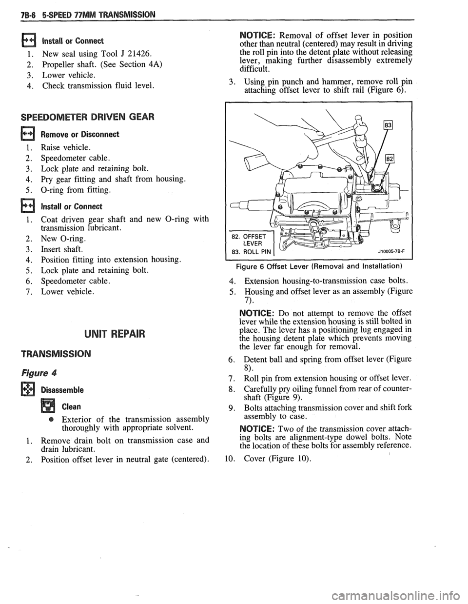
3. Using pin punch and hammer, remove roll pin
attaching offset lever to shift rail (Figure
6).
Figure 6 Offset Lever (Removal and Installation)
4. Extension housing-to-transmission case bolts.
5. Housing and offset lever as an assembly (Figure
7) *
NOTICE: Do not attempt to remove the offset
lever while the extension housing is still bolted in
place. The lever has a positioning lug engaged in
the housing detent plate which prevents moving
the lever far enough for removal.
6. Detent ball and spring from offset lever (Figure
8)
7. Roll pin from extension housing or offset lever.
8. Carefully pry oiling funnel from rear of counter-
shaft (Figure
9).
9. Bolts attaching transmission cover and shift fork
assembly to case.
NOTICE: Two of the transmission cover attach-
ing bolts are alignment-type dowel bolts. Note
the location of these bolts for assembly reference.
10. Cover (Figure 10). I
Page 1144 of 1825
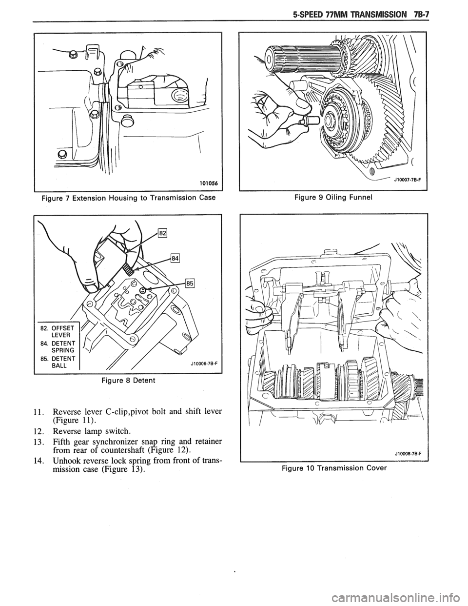
Figure 7 Extension Housing to Transmission Case Figure 9 Oiling
Funnel
Figure
8 Detent
11. Reverse lever C-clip,pivot bolt and shift lever
(Figure
1 I).
12. Reverse lamp switch.
13. Fifth gear synchronizer snap ring and retainer
from rear of countershaft (Figure
12).
14. Unhook reverse lock spring from front of trans-
mission case (Figure
13). Figure 10 Transmission Cover
Page 1150 of 1825
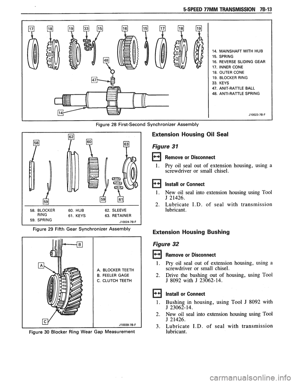
14. MAINSHAFT WITH HUB
15. SPRING
16. REVERSE SLIDING GEAR
17, INNER CONE
18. OUTER CONE
19. BLOCKER RING
33. KEYS
47.
ANIT-RAlTLE BALL
48. ANTI-RATTLE SPRING
Figure 28 First-Second Synchronizer Assembly
63. RETAINER
Figure 29 Fifth Gear Synchronizer Assembly
Extension Housing Oil Seal
Figure 31
Remove or Disconnect
1. Pry oil seal
out of extension housing, using a
screwdriver or small chisel.
Install or Connect
1. New oil seal into extension housing using Tool
J 21426.
2. Lubricate
I.D. of seal with transmission
lubricant.
Extension Housing Bushing
A. BLOCKER TEETH
B. FEELER GAGE
C. CLUTCH TEETH
Figure 32
rn Remove or Disconned
1. Pry oil seal out of extension housing, using a
screwdriver or small chisel.
2. Drive the bushing
out of housing, using Tool
J 8092 with J 23062-14.
Install or Connect
1. Bushing in housing, using Tool J 8092 with
J 23062-14.
2. New
oil seal into extension housing using
Tm1
J 21426.
3. Lubricate
I.D. of seal with transmission
Figure 30 Blocker Ring Wear Gap Measurement lubricant.
Page 1151 of 1825
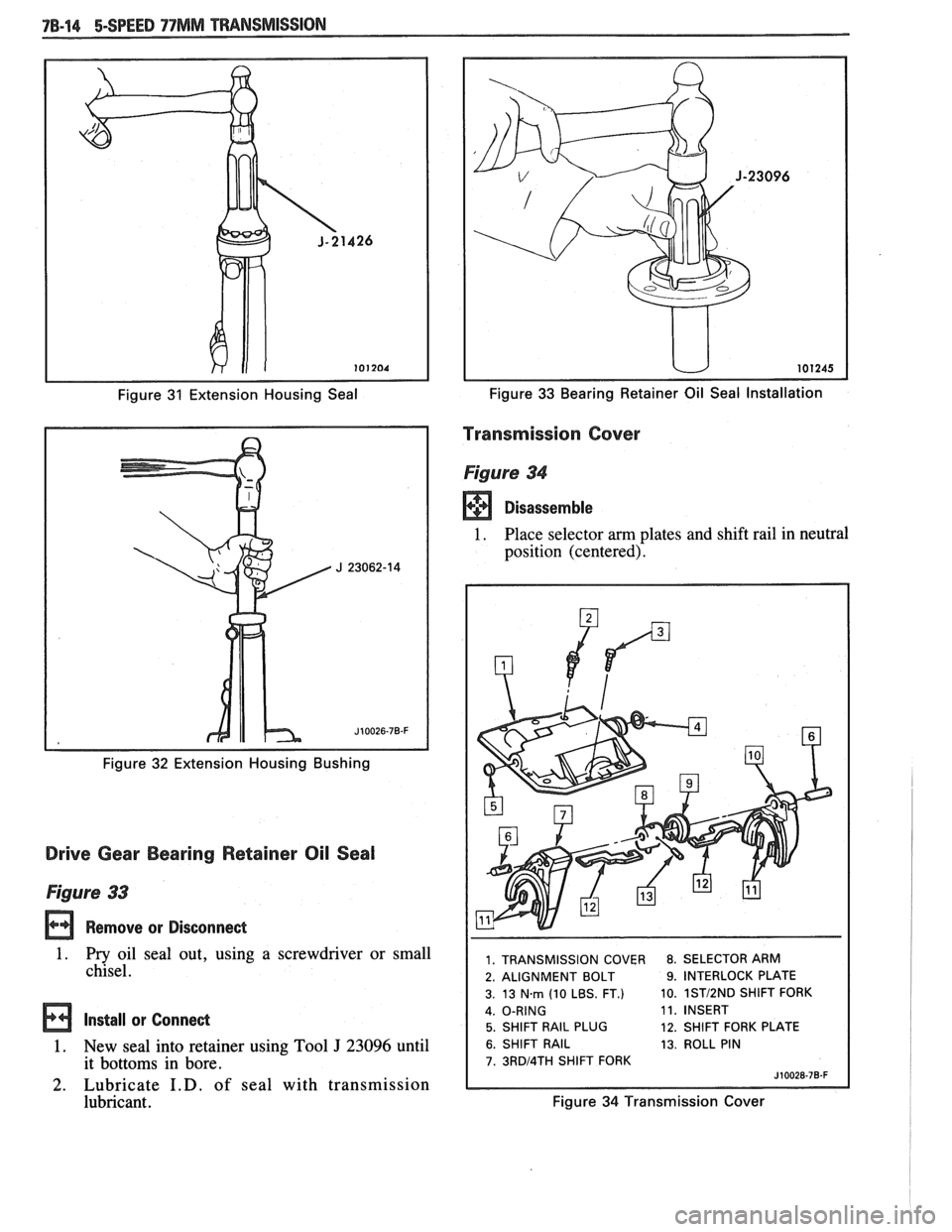
Figure 31 Extension Housing Seal
Figure
32 Extension Housing Bushing
Drive Gear Bearing Retainer Oil Seal
Figure 33
Remove or Disconnect
1. Pry oil seal out, using a screwdriver or small
chisel.
Install or Connect
1. New seal into retainer using Tool J 23096 until
it bottoms in bore.
2. Lubricate I.D. of seal with transmission
lubricant.
Figure 33 Bearing Retainer Oil Seal Installation
Transmission Cover
Figure 34
Disassemble
1. Place selector am plates and shift rail in neutral
position (centered).
1. TRANSMISSION COVER 8. SELECTOR ARM
2. ALIGNMENT BOLT
9. INTERLOCK PLATE
3. 13
Nm (10 LBS. FT.) 10. 1STI2ND SHlFT
FORK
11. INSERT
5. SHIFT RAIL PLUG 12. SHIFT FORK PLATE
6. SHIFT RAIL 13. ROLL PIN
7. 3RDl4TH SHlFT FORK
Figure 34 Transmission Cover
Page 1155 of 1825
78-18 5-SPEED 77MM TRANSMISSION
Blocker ring and fifth gear synchronizer in fifth
gear shift fork. Slide fork rail assembly and syn-
chronizer into position. (Figure 20)
Fifth gear synchronizer retainer and snap ring
(Figure 12).
Oiling funnel into rear of countershaft (Figure
9)
Position fifthlreverse shift lever in case.
Connect lever return spring to front of case.
Make sure reverse shift fork pin and fifth gear
shift rail pin are engaged with shift lever and
install fifth
gearlreverse lever, pivot bolt and
retaining clip. Coat pivot bolt threads with pipe
thread sealant
#lo52080 or equivalent.
Reverse lamp switch. Coat threads with pipe
thread sealant
# 1052080 or equivalent.
Speedometer gear and retaining clip.
Circlip.
Apply 3mm
(118in.) bead of RTV Sealant,
# 105275 1 or equivalent, to transmission cover
assembly.
Make sure all synchronizers are in the neutral
position and that the shift forks in the cover are
in the neutral (center) position. Lower cover
onto case while aligning shift forks and synchro-
nizer sleeves.
Center cover and install two dowel bolts.
Remaining cover bolts.
Tighten
@ Torque all cover bolts to 14 N*m (10 lbs.
ft.).
Apply 3mm (118 in.) bead of RTV Sealant,
#I05275 1 or equivalent, to extension housing
mating surface.
Coat detent spring with petroleum jelly and
insert in offset lever. Lubricate detent plate and
install detent ball in neutral position on plate.
Position offset lever in extension housing with
spring over detent ball. Slide lever and exten-
sion housing into position as an assembly.
Extension housing vent.
Press downward on offset lever to compress
detent spring and push lever and housing into
position.
Extension housing bolts. Apply pipe thread
sealant
#lo52080 or equivalent to threads of
top two bolts.
Tighten
@ Torque extension housing bolts to 30 Nm
(23 lbs. ft.)
Align and install roll pin in offset lever and shift
rail. 35. Damper
sleeve in offset lever.
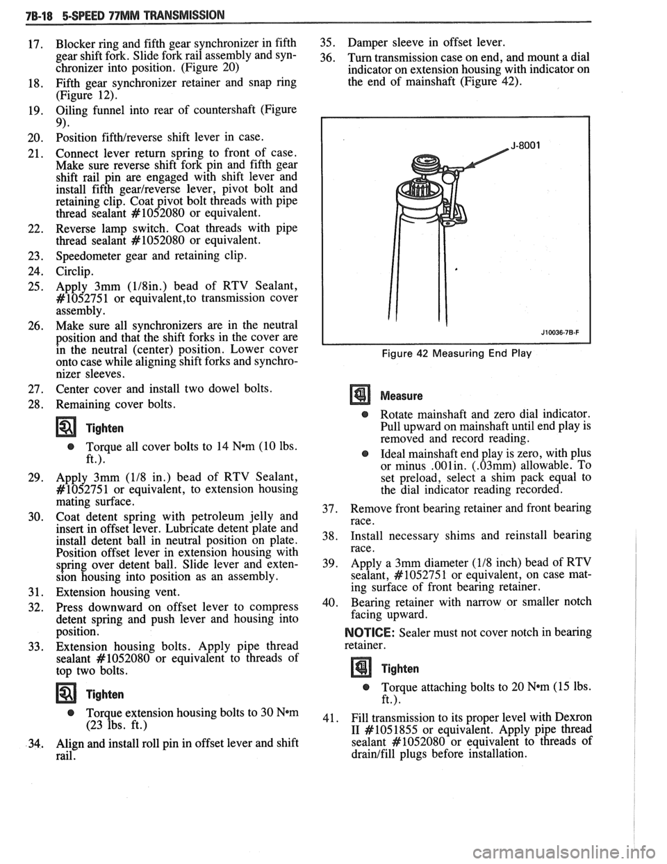
36. Turn transmission case on end, and mount a dial
indicator on extension housing with indicator on
the end of mainshaft (Figure 42).
Figure 42 Measuring End Play
Measure
@ Rotate mainshaft and zero dial indicator.
Pull upward on mainshaft until end play is
removed and record reading.
@ Ideal mainshaft end play is zero, with plus
or minus
.001in. (.03mm) allowable. To
set preload, select a shim pack equal to
the dial indicator reading recorded.
37. Remove
front bearing retainer and front bearing
race.
38. Install
necessary shims and reinstall bearing
race.
39. Apply
a 3mm diameter
(118 inch) bead of RTV
sealant,
#lo5275 1 or equivalent, on case mat-
ing surface of front bearing retainer.
40. Bearing retainer with narrow
or smaller notch
facing upward.
NOICE: Sealer must not cover notch in bearing
retainer.
Tighten
@ Torque attaching bolts to 20 N*m (15 lbs.
ft.).
41. Fill transmission to its proper level with
Dexron
I1 #I05 1855
or equivalent. Apply pipe thread
sealant
#lo52080 or equivalent to threads of
drainlfill plugs before installation.
Page 1158 of 1825
CLUTCH 7C-4
SECTION 76
CLUTCH
CONTENTS
GENERAL DESCRIPTION .......................... .. ............................................................. 7C-I
DIAGNOSIS ...................................................................................................................... 7C-3
Preliminary Checks ....................... ... ............................................................................ 7C-2
Bleeding Hydraulic Clutch System ................... .. .......................................................... 7C-2
ON-VEHICLE SERVICE ................................................................................................. 7C-5
Clutch Hydraulic System ................................................................................................. 7C-5
..................... Pressure Plate and Disc .. ........................................................................... 7C-6
Clutch Pedal ..................................................................................................................... 7C-6
Pilot Bearing .................................................................................................................. 7C-6
....................................................................................................... SPECIFICATIONS 7C-8
............................................................................................................ SPECIAL TOOLS 7C-8
GENERAL DESCRIPTION
COMPONENTS
The principal parts of a clutch system are: the
driving member and the operating members. Figure
7C-1 shows an exploded view of the clutch system.
DRIVEN MEMBERS (FIGURES 7C-1 AND 7C-2)
The driven member is the clutch disc with a
splined hub which is free to slide lengthwise along the
splines of the input shaft, but which drives the input
shaft through these same splines.
The driving and driven members are held in
contact by spring pressure. This pressure is exerted by
a diaphragm spring in the pressure plate assembly.
HYDRAULIC CLUTCH (FIGURE 7C-3)
A hydraulic clutch operating mechanism is used
on all models. The
mechanism consist of a remote
reservoir, clutch master cylinder and slave cylinder.
The remote reservoir is mounted to a bracket which
bolts to the power brake booster. The clutch master
cylinder is mounted on the cowl panel and the slave
cylinder is mounted on the bell housing. The clutch
master cylinder is operated directly off the clutch
pedal.
When the clutch pedal is pressed down, hydraulic
fluid under pressure from the clutch master cylinder
flows into the slave cylinder. Since the piston is also
connected to the clutch fork this lever moves the
release bearing into contact with the clutch cover
release fingers to disengage the clutch. The hydraulic
clutch system locates the clutch pedal height and
provides automatic clutch adjustment. No adjustment
of clutch linkage or pedal position is required.
OPERATING MEMBERS (FIGURE 7C-3)
HYDRAULIC CLUTCH FLUID
When adding fluid to or refilling the system after
The clutch release system is operated by service operations use GM Delco Supreme No. 11 hydraulic pressure and consists of the clutch pedal, brake fluid or an equivalent fluid that meets DOT 3 clutch master cylinder, clutch slave cylinder, clutch specifications. fork and clutch release bearing.
NOTICE: Do not use mineral or paraffin base oil in
the Clutch Hydraulic System. These fluids will
damage the rubber parts in the cylinders.
Page 1161 of 1825
7C.4 CLUTCH
CLUTCH DIAGNOSIS
CONDITION PROBABLE CAUSE CORRECTION
Fails to Release
(Pedal pressed to
floor shift lever a. Faulty pilot bearing. a. Replace bearing.
does not move freely b.
Faulty driven disc. b.
Replace disc.
in and out of
re- c. Fork off ball stud. c.
Install properly and*
verse gear) lubricate
fingers at
re-
lease bearing and ball stud.
d. Clutch disc hub
bind- d. Repair or replace
ing on clutch gear clutch
gear and/or disc.
spline.
e. Clutch disc warped e.
Replace disc (run-out
or bent. should
not exceed
.020").
* Very lightly lubricate
fingers.
a. Oil soaked driven a. Install new disc and
disc. correct
leak at its source.
b. Worn facing or
fac- b. Replace disc.
ing torn from disc.
c. Warped pressure c. Replace pressure plate
plate or flywheel. or flywheel.
d. Weak diaphragm
d. Replace pressure plate
spring. e. Driven plate not e. Make
30 to 40 normal
seated in. starts. CAUTION:
Do
not overheat.
f. Driven plate over- f. Allow to cool.
Slipping
Page 1162 of 1825
CLUTCH 7C-5
Grabbing (Chattering)
Rattling
- Transmission
Click
Release Bearing Noise
with Clutch Fully
Engaged
Noisy
Pedal Stays on Floor
When Disengaged heated.
a. Oil
on facing. Burned
or glazed facings.
b. Worn splines
on
clutch gear.
c. Warped pressure
plate or flywheel.
d. Burned or smeared
resin on flywheel or
pressure plate.
a. Weak retracting
springs.
b. Release fork loose
on ball stud or in bear-
ing groove.
c. Oil in driven plate
damper.
d. Driven plate damper
spring failure.
a. Release bearing bind-
ing on transmission
bearing retainer.
b. Fork improperly in-
stalled. a. Worn release bearing.
b. Fork off ball stud
(heavy clicking).
c. Pilot bearing loose
in crankshaft.
a. Bind in release
bearing.
b. Springs weak in
pressure plate. a.
Install new disc and
correct leak.
b. Replace transmission
clutch gear.
c. Replace pressure plate
or flywheel.
d. Sand off if superficial,
replace burned or heat
checked parts.
a. Replace pressure plate.
b. Check ball stud and
retaining.
c. Replace driven disc.
d. Replace driven disc.
a. Clean, relubricate,
check for burrs, nicks,
etc.
b. Install properly.
a. Replace bearing.
b. Install properly and
lubricate fork fingers
and bearing.
c. See Section
6 for
bearing fits.
Lubricate and free-up
release bearing.
b. Replace pressure
plate.
ON-VEHICLE SERVICE
CLUTCH HYDRAULIC SYSTEM 7. Remove the clutch fluid reservoir from bracket.
NOTICE: The clutch hydraul~c 4ystern is serviced 8. Pull brake niaster cylinder forward for access to
as a complete unit, it has been bled
of air and filled clutch master cylinder.
with fluid. Individual components of the system 9. Remove the clutch master cylinder from cowl.
are
not available separately. 10. Hoist vehicle.
1 1. Remove the slave cvlinder heat shield.
Prior to any vehicle service that requires removal of
the slave cylinder
(i.e., transmission and clutch housing
removal), the
master cylinder push rod must be
disconnected from the clutch pedal. If not discon-
nected, permanent damage to the slave cylinder will
occur if the clutch pedal is depressed while the slave
cylinder is disconnected.
Removal
1. Disconnect negative battery cable.
2. Remove the steering column trim cover.
3. Remove the hush panel.
4. Discoonect the master cylinder push rod from
clutch pedal.
5. Remove the clutch master cylinder to cowl nuts.
6. Remove the brake booster to cowl nuts.
12. Remove the slave cylinder from bell housing.
13. Lower vehicle.
14. Remove the clutch hydraulic system from engine
compartment.
Installation
1. Position
hydraulic clutch master cylinder at cowl
and feed slave cylinder drown to bell housing
area.
2. Pilot clutch master cylinder push rod through
cowl and position master cylinder to cowl with
U
bolt.
3. Connect brake booster to cowl.
4. Pilot clutch master cylinder
U bolt through
clutch braces and torque nuts.
5. Torque brake master cylinder to cowl nuts.