1988 PONTIAC FIERO oil
[x] Cancel search: oilPage 1742 of 1825
REAR QUARTERS - F STYLE 6N-7
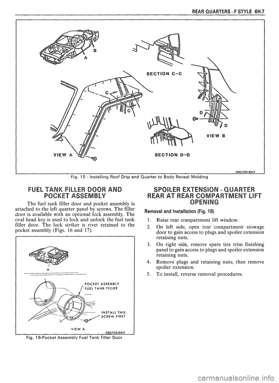
Fig. 15 - Installing Roof Drip and Quarter to Body Reveal Molding
FUEL TANK FILLER DOOR AND SPOILER EXTENSION - QUAREER
POCKET ASSEMBLY REAR A"FREAR COMPARTMENT LIFT
The fuel tank filler door and pocket assembly is OPENING
attached to the left quarter panel by screws. The filer Removal and (Fig, door is available with an o~tional lock assemblv. The
oval head key is used to
loik and unlock the fuil tank 1. Raise rear compartment lift window.
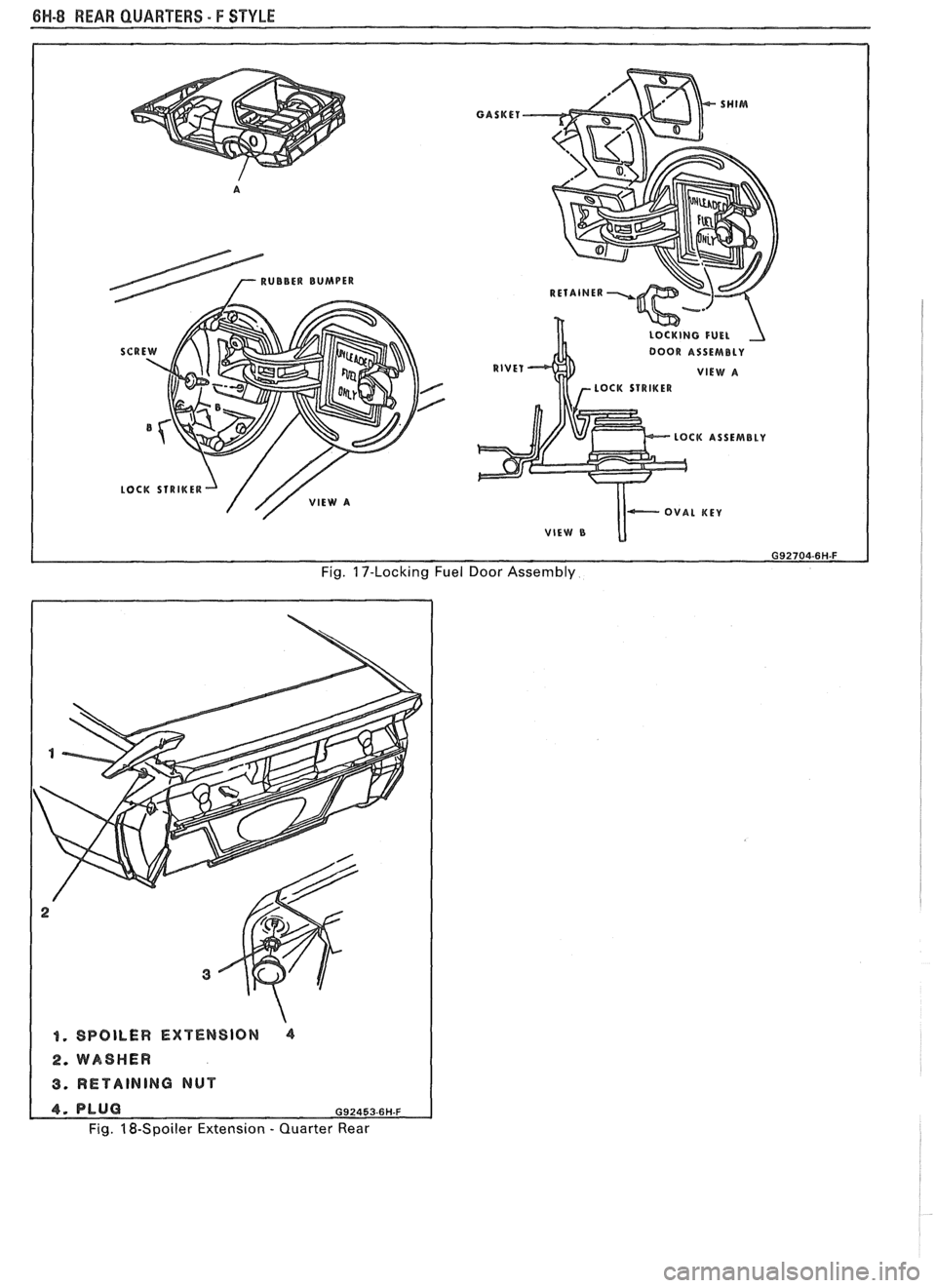
filler door. The lock striker is rivet retained to the
2. 0, left side, open rear compartment stowage pocket assembly (Figs. 16 and 17). door to gain access to plugs and spoiler extension
retaining nuts.
3. On right side, remove spare tire trim finishing
panel to gain access to plugs and spoiler extension
retaining nuts.
4. Remove plugs and retaining nuts; then remove
spoiler extension.
5. To install, reverse removal procedures.
POCKET ASSEMBLY FUEL TANK FILLER
INSTALL THIS SCREW FIRST
VIEW A
Fig. 16-Pocket Assembly Fuel Tank Filler Door
Page 1743 of 1825
6H-8 REAR QUARTERS - F STYLE
LocK sTR1KER-J /// VIEW A
GASKET
LOCKING FUEL 1
DOOR ASSEMBLY
RIVET VlEW A r- LOCK STRIKER
LOCK ASSEMBLY
I VlEW B
Fig. 17-Locking Fuel Door Assembly
1. SPOILER EXTENSION 4
2. WASHER
3. RETAINING NUT
Fig. 18-Spoiler Extension - Quarter Rear
Page 1744 of 1825
REAR END - F STYLE 7H-1
SECTION 7H
REAR END
NOTICE: The anti-theft label found on some major sheet metal, engines, and transmissions must be masked
prior to painting, rustproofing, undercoating, etc. The mask
must be removed following the above operations.
Failure to keep the label clean and readable may result in liability for violation of Federal Vehicle Theft Prevention
Standard, and subject the vehicle owner to possible suspicion that the part was stolen.
CONTENTS
Moldings, Emblems and Name Plates ............ 7H- 1
Compartment Lift Window
.......................... ... 7H-2
Adjustments ........................... .. ................ 7H-2
Removal and Installation ............................. 7H-3
Removal of Lift Window Panel from
Glass
....................................................... 7H-3
Glass Replacement and Adjustment ........... 7H-5
Gas Support Assembly ............................. 7H-7
Lock Cylinder ....................... .. .............. 7H-8
REAR COMPARTMENT
The service operations for the removal,
installation, adjustment and sealing of the
compartment lift window assembly, individual
hardware components, moldings, emblems and name
plates attached to the compartment lift window or rear
end panel are contained in this section.
MOLDINGS, EMBLEMS AND NAME PLAES
The moldings, emblems and name plates used on
the rear compartment and rear end panels are adhesive
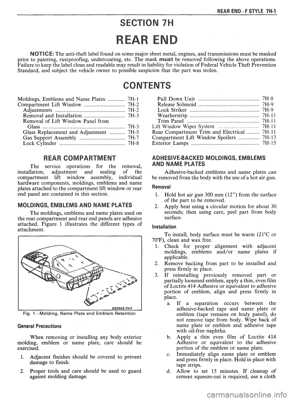
attached. Figure 1 illustrates the different types of
attachment.
Fig. 1 - Molding, Name Plate and Emblem Retention
General Precautions
When removing or installing any body exterior
molding, emblem or name plate, care should be
exercised.
1. Adjacent
finishes should be covered to prevent
damage to finish.
...................................... Pull Down Unit 7H-8
.......................................... Release Solenoid 7H-9
......... ..................................... Lock Striker ... 7H-9
................... ....................... Weatherstrip .. 7H- 1 1
.................................................. Trim Panel 7H- 1 1
..................... Lift Window Wiper System 7H- l l
......... Rear Compartment Trim and Electrical 7H- 1 1
............... Compartment Lift Window Spoilers 7H- 13
.......................................... Exterior Lamps 7H- 15
ADHESIVE-BACKED MOLDINGS, EMBLEMS
AND NAME PLATES
Adhesive-backed emblems and name plates can
be removed from the body with the use of a hot air gun.
Removal
1.
Hold hot air gun 300 mm (12") from the surface
of the part to be removed.
2. Apply heat using a circular motion for about 30
seconds; then using care, peel part from body
surface.
Installation
To install, body surface must be warm (21°C or
70"F), clean and wax free.
1. Check for proper alignment with adjacent
moldings, emblems and/or name plates if
applicable.
2. Remove backing from part to be installed and
press firmly in place.
3. If reinstalling previously removed part or
partially loosened emblem, apply a thin, even film
of Loctite 414 Adhesive or equivalent to adhesive
portion of emblem, align and press firmly in
place.
a. If a separation occurs between the
adhesive-backed tape and name plate or
emblem (tape remains on body panel), do
not remove tape from body. Wipe back of
name plate or emblem and adhesive tape
with oil-free naphtha.
b. Apply a thin even film of Loctite 414
Adhesive or equivalent to the adhesive
portion of the emblem or name plate.
c. Immediately align name plate or emblem
and press firmly in place. Hold in place with
tape strips.
2. Proper tools and care should be used to guard d. Allow to set 15 minutes. If cleanup of
against molding damage. cement squeeze-out is required, use a cloth
Page 1745 of 1825
71.1-2 REAR END - F STYLE
dampened slightly with oil-free naphtha;
then remove tape strips.
COMPARTMENT LIFT WINDOW MOLDING
Refinishing
1. Mask off area(s) adjacent to molding(s).
2. Clean with Ditzler's DX-440 wax and grease
removing solvent or equivalent.
3. Sand with
#400 grit wet or dry sandpaper.
4. Clean
with wax and grease removing solvent.
5. Prime with Ditzler's
epoxy chromate primer DP
40/40 1 or equivalent.
6. Sand with
#500 grit wet or dry sandpaper.
7. Clean with wax and grease removing solvent.
8. Top
coat with flat black acrylic lacquer.
9. Remove masking tape.
When using any of the listed materials, follow the
manufacturer's label directions for application
procedures and drying time.
Removal
CAUTION: When working with glass
assemblies, the use of personal
protection items such as safety
glasses and work gloves is
recommended to minimize the chance
of personal injury should the glass
break.
1. Remove compartment lift window from body, as
described later in this section, and with the aid of
a helper, place upside down on a protected work
surface.
2. Remove upper hinges.
3. Remove screws retaining moldings to panel.
CAUTION: Perform the urethane
burn-out operation in a well ventilated
area and avoid direct inhalation of the
fumes being emitted as these fumes
may be hazardous.
4. Using an acetylene torch with a number 2 tip,
start at the top of either the right or left side
molding and apply heat for a distance of 200 mm
(8") to outboard edge of molding for 30 to 60
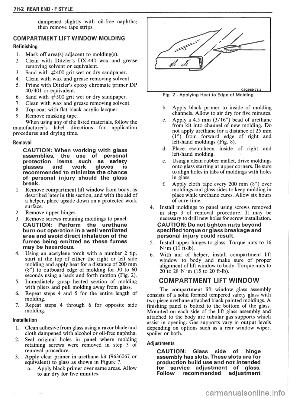
seconds using a back and forth motion (Fig. 2).
5. Immediately grasp heated section of molding
with pliers and pull molding away from glass.
6. Repeat steps
4 and 5 for the entire length of
molding.
7. Repeat steps 4 through 6 for opposite side
molding.
Installation
1. Clean adhesive from glass using a razor blade and
cloth dampened with alcohol or oil-free naphtha.
2. Seal original holes in panel where molding
retaining screws were removed in step 3 of
removal procedure.
3. Apply clear primer in urethane kit (9636067 or
equivalent) to glass as shown in Figure 7.
a. Apply
black primer over same areas. Allow
to air dry for five minutes.
Fig. 2 -Applying Heat to Edge of Molding
b. Apply
black primer to inside of molding
channels. Allow to air dry for five minutes.
c. Apply a 4.5 mm
(3/16") bead of urethane
from kit into channel of new molding. Do
not apply urethane for a distance of
25 mm
(1") from forward edge of right and
left-hand moldings (Fig. 8).
d. Place escutcheon inside of right and
left-hand molding.
e. Using a
clean rubber mallet, drive moldings
onto glass starting at upper corners. Be sure
to align holes in tabs of moldings with holes
in glass.
f. Apply cloth tape every 200 mm (8") over
moldings and glass sides to keep molding in
place while urethane cures. Allow six hours
of cure time.
4. Install moldings to panel using screws removed
in step 3 of removal procedure. It may be
necessary to drill new holes for screw installation.
CAUTION: Do not tighten nuts beyond
specified torque or glass breakage and
personal injury could result.
5. Install
upper hinges to glass. Torque nuts to 16
N-m (1 1 ft-lb).
6. With aid of helper, install compartment lift
window to body and make sure of proper
alignment of lift window to body. Torque nuts to
20 to 28
N-m (15 to 20 ft-lb).
COMPARTMENT LIFT WINDOW
The compartment lift window glass assembly
consists of a solid formed tempered safety glass with
two piece urethane attached black painted moldings. A
finishing panel is bolted to the bottom of the glass.
Mounted on each side of the lift glass assembly and
attached to the body are tubular gas supports which
assist in opening. Gas supports vary in output levels
depending on options such as a rear window wiper,
spoiler or both.
Adjustments
CAUTION: Glass side of hinge
assembly has slots. These slots are for
production build use and not intended
for service adjustment of
glass.
Follow recommended adjustment
Page 1756 of 1825
REAR END - F STYLE 7W-13
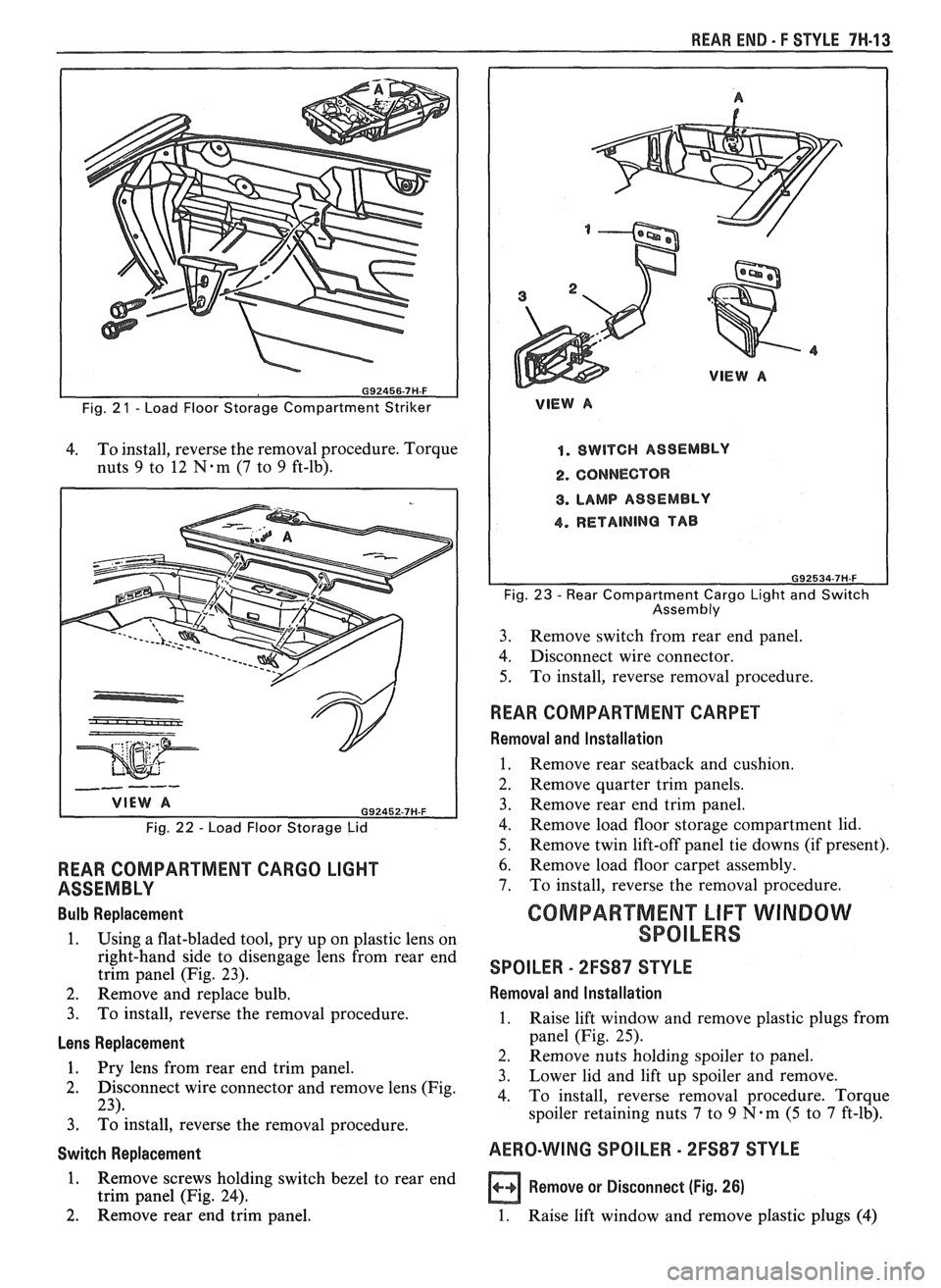
Fig. 2 1 - Load Floor Storage Compartment Striker
4. To
install, reverse the removal procedure. Torque
nuts
9 to 12 N-m (7 to 9 ft-lb).
Fig. 22 - Load Floor Storage Lid
REAR COMPARTMENT CARGO LIGHT
ASSEMBLY
Bulb Replacement
1. Using a flat-bladed tool, pry up on plastic lens on
right-hand side to disengage lens from rear end
trim panel (Fig. 23).
2. Remove and replace bulb.
3. To install, reverse the removal procedure.
Lens Replacement
1. Pry lens from rear end trim vanel.
2. Disconnect wire connector and remove lens (Fig.
23).
3. ~d install, reverse the removal procedure.
Switch Replacement
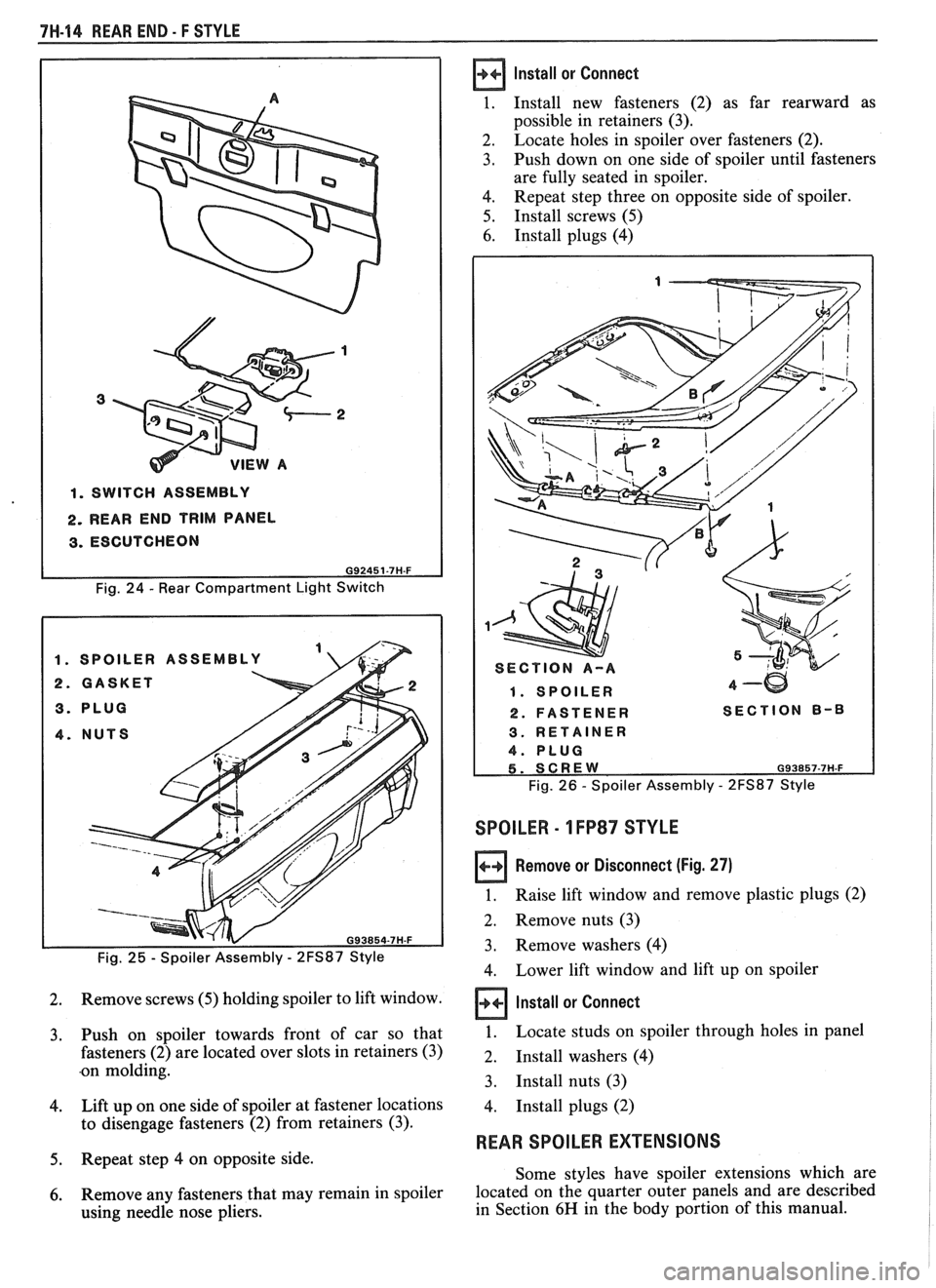
1. Remove screws holding switch bezel to rear end
trim panel (Fig. 24).
2. Remove rear end trim panel.
VlEW A
1. SWITCH ASSEMBLY
2. CONNECTOR
8. LAMP ASSEMBLY
4. RETAINING TAB
Fig. 23 - Rear Compartment Cargo Light and Switch
Assembly
3. Remove
switch from rear end panel.
4. Disconnect wire connector.
5. To
install, reverse removal procedure.
WEAR COMPARTMENT CARPET
Removal and Installation
1. Remove rear seatback and cushion.
2. Remove quarter trim panels.
3. Remove rear end trim panel.
4. Remove load floor storage compartment lid.
5. Remove twin lift-off panel tie downs (if present).
6. Remove load floor carpet assembly.
7. To install, reverse the removal procedure.
GOMPARTMEN"FLlFT WINDOW
SPOILERS
SPOILER - 2FS87 STYLE
Removal and lnstallation
1. Raise lift window and remove plastic plugs from
panel (Fig. 25).
2. Remove nuts holding spoiler to panel.
3. Lower lid
and lift up spoiler and remove.
4. To install, reverse removal procedure. Torque
spoiler retaining nuts
7 to 9 N.m (5 to 7 ft-lb).
AERO-WING SPOILER - 2FS87 STYLE
a Remove or Disconnect (Fig. 26)
1. Raise lift window and remove plastic plugs (4)
Page 1757 of 1825
7H-14 REAR END - F STYLE
1. SWITCH ASSEMBLY
2. REAR END TRIM PANEL
3. ESCUTCHEON
Fig. 24 - Rear Compartment Light Switch
Fig.
25 - Spoiler Assembly - 2FS87 Style
2. Remove screws (5) holding spoiler to lift window.
3. Push on spoiler towards front of car so that
fasteners
(2) are located over slots in retainers (3)
.on molding.
4. Lift up on one side of spoiler at fastener locations
to disengage fasteners
(2) from retainers (3).
5. Repeat step 4 on opposite side.
6. Remove any fasteners that may remain in spoiler
using needle nose pliers.
Install or Connect
1. Install new fasteners (2) as far rearward as
possible in retainers
(3).
2.
Locate holes in spoiler over fasteners (2).
3. Push down on one side of spoiler until fasteners
are fully seated in spoiler.
4. Repeat step three on opposite side of spoiler.
5. Install screws (5)
6. Install plugs (4)
1. SPOILER 4-w
2. FASTENER SECTION B-8
Fig. 26 - Spoiler Assembly - 2FS87 Style
SPOILER - 1 FP87 STYLE
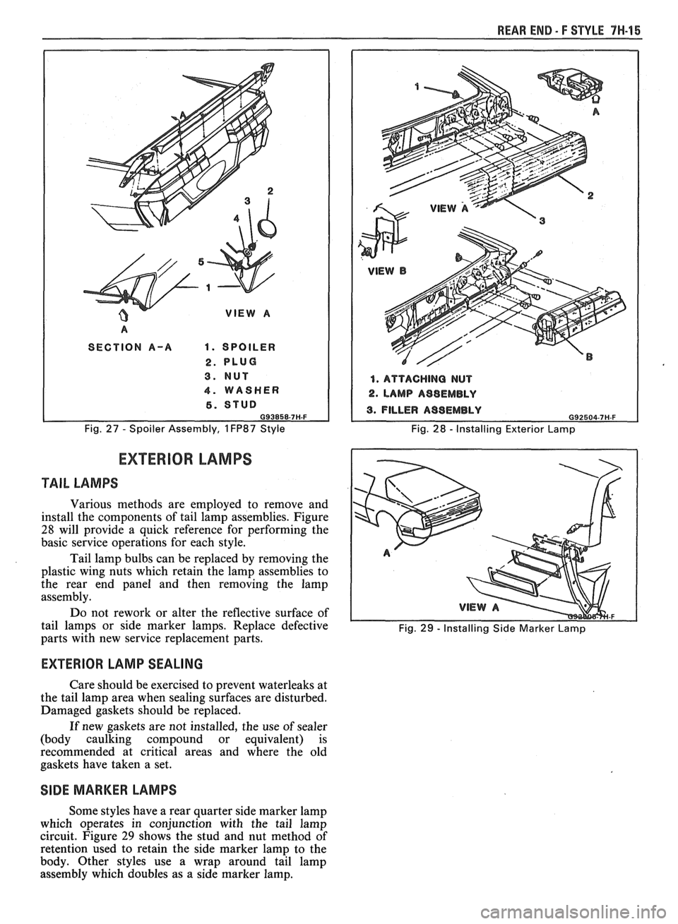
Remove or Disconnect (Fig. 27)
1. Raise lift window and remove plastic plugs (2)
2.
Remove nuts (3)
3. Remove washers (4)
4. Lower lift window and lift up on spoiler
Install or Connect
1. Locate studs on spoiler through holes in panel
2. Install washers (4)
3.
Install nuts (3)
4.
Install plugs (2)
REAR SPOILER EXTENSIONS
Some styles have spoiler extensions which are
located on the quarter outer panels and are described
in Section
6H in the body portion of this manual.
Page 1758 of 1825
WEAR END - F STYLE 7H-15
A
SECTION A-A 1. SPOILER
2. PLUG
3. NUT
4. WASHER
6. STUD 093858-7H.F
Fig. 27 - Spoiler Assembly, 1 FP87 Style
1. ATTACHING NUT
2. LAMP A98EMBLY
Fig. 28 - Installing Exterior Lamp
EXTERIOR LAMPS
TAIL LAMPS
Various methods are employed to remove and
install the components of tail lamp assemblies. Figure
28 will provide a quick reference for performing the
basic service operations for each style.
Tail lamp bulbs can be replaced by removing the
plastic wing nuts which retain the lamp assemblies to
the rear end panel and then removing the lamp
assembly.
Do not rework or alter the reflective surface of
tail lamps or side marker lamps. Replace defective
Fig. 29 - Installing Side Marker Lamp parts with new service replacement parts.
EXTERIOR LAMP SEALING
Care should be exercised to prevent waterleaks at
the tail lamp area when sealing surfaces are disturbed.
Damaged gaskets should be replaced.
If new gaskets are not installed, the use
of sealer
(body caulking compound or equivalent) is
recommended at critical areas and where the old
gaskets have taken a set.
SIDE MARKER LAMPS
Some styles have a rear quarter side marker lamp
which operates in conjunction with the tail lamp
circuit. Figure
29 shows the stud and nut method of
retention used to retain the side marker lamp to the
body. Other styles use a wrap around tail lamp
assembly which doubles as a side marker lamp.
Page 1759 of 1825
7H-16 REAR END - F STYLE
CENTER HIGH-MOUNTED STOP LAMP
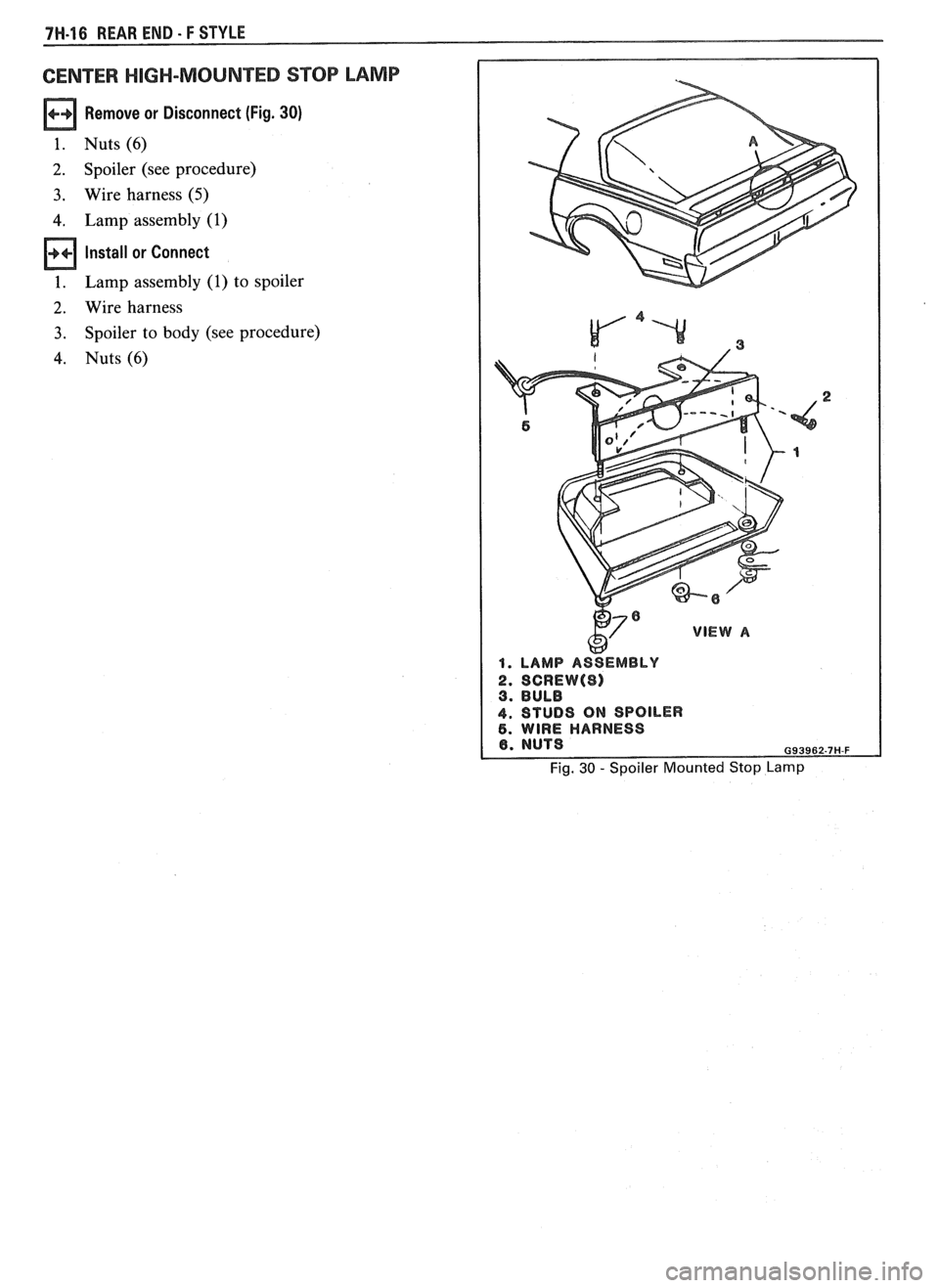
Remove or Disconnect (Fig. 30)
1. Nuts(6)
2. Spoiler (see procedure)
3. Wire harness (5)
4. Lamp assembly (1)
Install or Connect
1. Lamp assembly (1) to spoiler
2. Wire harness
3. Spoiler to body (see procedure)
4. Nuts(6)
w 1. LAMP ASSEMBLY
4. STUBS ON SPOILER 6. WIRE HARNESS
Fig. 30 - Spoiler Mounted Stop Lamp