1988 PONTIAC FIERO oil
[x] Cancel search: oilPage 1760 of 1825
ROOF - F STYLE 8H-1
SECTION 8H
ROOF
CONTENTS
Formed Headlining .......................................... 8H- 1
Interior Roof Attachments
.............................. 8H- 1
Interior Garnish Moldings .............................. 8H-2
Exterior Roof Moldings and
Attachments
.................................... .... ... 8H-3
Twin Lift-off Panel
......................................... 8H-3
Convertible Top
Top Operation
............................................ 8H-7
Header Inner Garnish
................................. 8H-8
"A" Pillar Inner Garnish
........... .;. .............. 8H-9
Header
"A" Pillar Seal ................................ 8H-9
Side Rail Seal and Retainer
......................... 8H-9
Main Pillar Seal and Retainer
..................... 8H-9
No.
5 Bow Seal .......................................... 8H-9
No. 1 Bow Garnish Molding
....................... 8H-9
Top Cover Assembly
.................................... 8H- 1 1
Side Stay Pads ............................................. 8H-13
Rear Stay Pads ............................................ 8H- 13
No.
1 and No. 2 Bows ................................. 8H- 13 NO. 3
BOW
.................................................... 8H-15
NO. 4 BOW ................................................ 8H-15
NO. 5 BOW ................................................. 8H-15
Top Stack Assembly Complete .................... 8H- 16
Quarter Inner Upper Trim Cap
.................. 8H- 17
Quarter Trim Panel
.................................... 8H- 17
Quarter Cap Belt Molding
........................... 8H- 17
Tonneau Panel Latch
................................. 8H- 17
Tonneau Release Solenoid
........................... 8H- 17
No. 5 Bow Release Handle
.......................... 8H- 19
No.
5 Bow Latch ....................................... 8H-19
Tonneau Panel
.......................................... 8H- 19
Tonneau Panel Seal
............................. ......... 8H-20
Deck Lid Spoiler ........................................ 8H-2 1
Center High Mount Stop Lamp .................. 8H-21
Deck Lid .................................................... 8H-21
Deck Lid Panel Seal
................................. 8H-22
Door Cap Belt Molding ............................... 8H-22
Front Belt Retractor Assembly ................... 8H-22
FORMED HEADLINING 1. Load the headlining through the rear
The one-piece formed headlining (Fig. 1) consists
of a molded fiberglass substrate covered with a foam
and cloth facing. The one-piece construction requires
the headlining be serviced as a complete assembly.
The headlining is held partially in place by
retaining fasteners located in the headlining which fit
into slots in the roof panel. Final attachment is
accomplished when the interior moldings and
attaching screws that retain the sunshade brackets,
dome lamp base and coat hooks are installed.
Removal
1. Remove the following items:
e Back body opening upper garnish molding
r Windshield side upper garnish molding (1,
Fig. 3 or
6)
e Rear vertical garnish molding
a Windshield header courtesy reading and
console lamp
e Sunshades
e Partially remove shoulder belt bezel and
belt
a Coat hooks and rail panel inserts
2. Grasp headlining assembly with both hands at
outer edges and move to the right of centerline to
disengage fastener assemblies from front
attaching slots.
3. Remove headlining assembly through right front
door.
lnstallation
Care must be exercised when loading assembly.
Excessive flexing may result in damage. compartment
opening.
2. Align headlining with cutouts for sunshades and
dome lamp and install sunshade brackets and
dome lamp base. Do not tighten sunshade bracket
and dome lamp attaching retainers completely
until headlining is aligned properly at all
hardware attaching locations.
3. Align headlining to roof inner panel with
fasteners positioned over holes in roof panel and
using palm of hand, push up on headlining at
fastener locations.
4. Install all previously removed hardware and
interior moldings.
INTERIOR ROOF ATTACHMENTS
DOME LAMPS
The dome lamp operates in conjunction with the
door jamb switch and/or the
headlamp switch. The
dome lamp harness extends up the right windshield
pillar, outboard of the sunshade support and across the
roof inner panel to the dome lamp.
Removal and Installation (Typical)
1. Grasp lens portion of dome lamp assembly,
squeeze and pull down to remove.
2. Remove bulb from terminal clips.
3. Remove retainers from studs.
4. Disengage wire harness from lamp housing and
remove dome lamp housing.
5. To install dome lamp assembly, reverse removal
procedure.
Page 1762 of 1825
ROOF - F STYLE 8H-3
EXTERlOR ROOF MOLDINGS AND
ATTACHMENTS
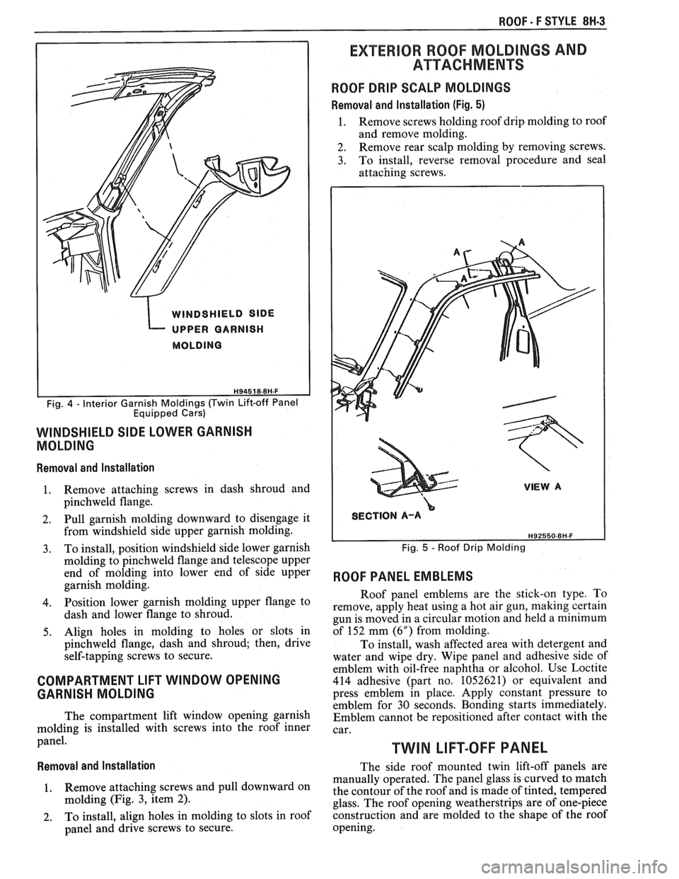
ROOF DRIP SCALP MOLDINGS
Removal and Installation (Fig. 5)
1. Remove screws holding roof drip molding to roof
and remove molding.
2. Remove rear scalp molding by removing screws.
3. To install, reverse removal procedure and seal
WINDSHIELD SlDE
UPPER GARNISH
MOLDING
Equipped Cars)
WINDSHIELD SIDE LOWER GARNISH
MOLDING
Removal and Installation
1. Remove attaching screws in dash shroud and
pinchweld flange.
2. Pull garnish molding downward to disengage it
SECTION A-A
from windshield side upper garnish molding.
3. To install, position windshield side lower garnish Fig. 5 - Roof Drip Molding
molding to pinchweld flange and telescope upper
end of molding into lower end
of side upper ROOF PANEL EMBLEMS garnish molding.
Roof panel emblems are the stick-on type. To
4. lower garnish flange to remove, apply heat using a hot air gun, making certain dash and lower flange to shroud.
gun is moved in a circular motion and held a minimum
5. Align holes
in molding to holes or slots in of 152 mm
(6") from molding.
pinchweld flange, dash and shroud; then, drive
To install, wash affected area with detergent and
self-tapping screws to secure.
water and wipe dry. Wipe panel and adhesive side of
emblem with oil-free naphtha or alcohol. Use Loctite
COMPARTMENT LIFT WINDOW OPENING 414 adhesive (part no. 1052621) or equivalent and
GARNISH MOLDING press emblem in place. Apply constant pressure to
emblem for 30 seconds. Bonding starts immediately.
The compartment lift window opening garnish Emblem cannot be repositioned after contact with the
molding is installed with screws into the roof inner
car. panel. TWIN LIFT-OFF PANEL
Removal and Installation The side roof mounted twin lift-off panels are
manually operated. The panel glass is curved to match
Remove attaching screws and pull downward On the contour of the roof and is made of tinted, tempered
molding (Fig. 3, item 2).
glass. The roof opening weatherstrips are of one-piece
2. To install, align holes in molding to slots in roof construction and are molded to the shape of the roof
panel and drive screws to secure. opening.
Page 1776 of 1825
ROOF - F STYLE 8H-17
a Inspect
Top stack assembly fit to body.
Adjust
Top stack as necessary by loosening nuts
and shifting top stack
6. Tighten nuts to 10
Nem (13 ft-lbs)
QUARTER INNER UPPER TRlM CAP
Fig. 18
Remove or Disconnect
1. Lower top completely.
2. Screws
(2)
3. Quarter
inner upper trim cap and bezel
Install or Connect
.. Quarter inner upper trim cap and bezel
2. Screws (2)
QUARTER TRlM PANEL
Fig. 18
Remove or Disconnect
1. Rear seat cushion
2. Sill
plate and carpet retainer
3. Quiarter inner upper trim cap
4. Lock pillar finish molding
5. Screws
6. Pull quarter trim panel out and disconnect
speaker wire connector
7. Push seat belt through slot in trim panel
8. Quarter trim panel
Install or Connect
.. Position quarter trim panel to body. Thread seat
belt through slot in trim panel and connect wire
connector to speaker.
2. Screws
3. Lock pillar finish molding
4. Quarter
inner upper tirm cap
5. Sill plate and carpet retainer
6. Rear seat cushion
QUARTER CAP BELT MOLDING
Fig. 19
The quarter cap belt moldings are attached to the
body by screws and adhesive tape shown in Figure 19.
The quarter cap belt molding can be removed from the
body with the use of a hot air gun to break the adhesive
tape bond.
Important
When removing or installing quarter cap
belt molding, care should be exercised.
Adjacent finishes should be protected to
prevent damage to finish.
e Proper tools and care should be used to
guard against molding damage.
Remove or Disconnect
1.
Quarter inner upper trim cap
2. Screws (1)
3. Quarter cap belt molding using hot air gun held
about 300 mm (12") from the surface. Apply heat
in a circular motion and carefully lift the molding
from the body surface.
e Wash quarter panel area with soap and
water and wipe dry.
Wipe quarter panel and adhesive side of
molding with a clean rag using oil-free
Naptha or alcohol to remove all traces of
adhesive tape from quarter panel and back
side of molding.
Install or Connect
1.
Apply a double-coated adhesive tape such as 3M
Super Automotive Attachment Tape (Part
Number 4210) or equivalent to the molding.
2. Quarter cap belt molding warm quarter panel
with heat lamp or heat gun about 21°C (70°F).
Align molding and press firmly in place.
3. Screws (1)
4. Quarter inner trim cap (see procedure)
TONNEAU PANEL LATCH
Fig, 20
Remove or Disconnect
1. Quarter trim panel (see procedure)
2. Cable (1)
3. Screws (3)
4. Latch (4)
Install or Connect
1. Latch (4)
2. Screws (3)
3. Cable (1)
4. Quarter trim panel (see procedure)
Important
Latch as required and retighen screws.
TONNEAU RELEASE SOLENOID
Fig, 20
Remove or Disconnect
1. Quarter trim panel (see procedure)
2. Cable from latch p
3. Wire connector (6)
4. Screws (7)
5. Solenoid (8)
Page 1780 of 1825
ROOF - f STYLE 8N-21
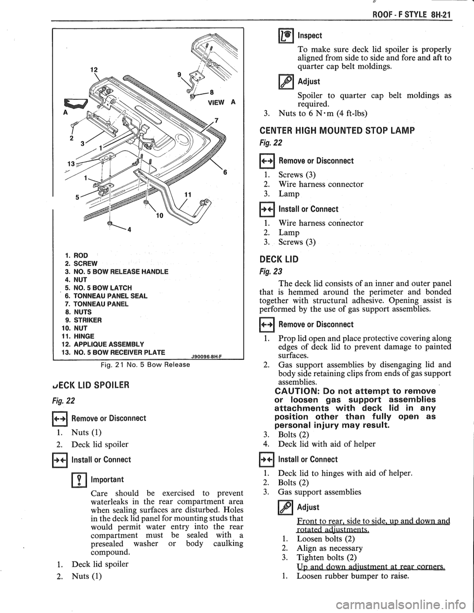
1. ROD
2. SCREW
3. NO. 5 BOW RELEASE HANDLE
4. NUT
5. NO. 5 BOW LATCH
6. TONNEAU PANEL SEAL
7. TONNEAU PANEL
8. NUTS
9. STRIKER
10. NUT
11. HINGE
12. APPLIQUE ASSEMBLY
Fig. 2 1 No. 5 Bow Release
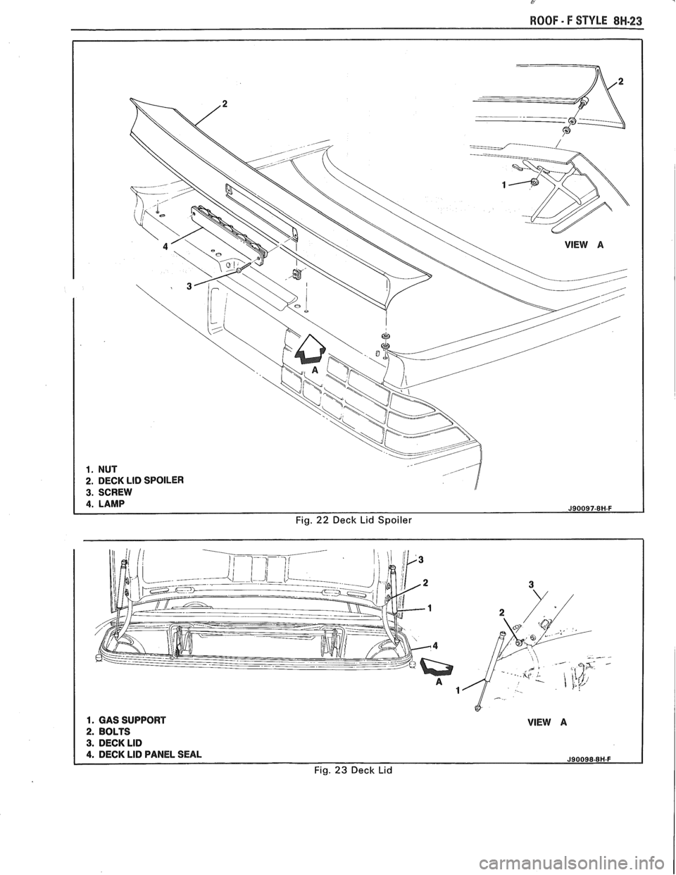
JECK LID SPOILER
Fig. 22
Remove or Disconnect
1. Nuts (1)
2. Deck lid spoiler
Install or Connect
Important
Care should be exercised to prevent
waterleaks in the rear compartment area
when sealing surfaces are disturbed. Holes
in the deck lid panel for mounting studs that
would permit water entry into the rear
compartment must be sealed with a
presealed washer or body caulking
compound.
1. Deck lid spoiler
2. Nuts (1)
Inspect
To make sure deck lid spoiler is properly
aligned from side to side and fore and aft
to
quarter cap belt moldings.
Adjust
Spoiler to quarter cap belt moldings as
required.
3. Nuts to
6 N.m (4 ft-lbs)
CENTER HIGH MOUNTED STOP LAMP
Fig. 22
Remove or Disconnect
1. Screws (3)
2. Wire harness connector
3. Lamp
Install or Connect
1. Wire harness connector
2. Lamp
3. Screws (3)
DECK LID
Fig. 23
The deck lid consists of an inner and outer panel
that is hemmed around the perimeter and bonded
together with structural adhesive. Opening assist is
performed by the use of gas support assemblies.
Remove or Disconnect
1. Prop
lid open and place protective covering along
edges of deck lid to prevent damage to painted
surfaces.
2. Gas support
assemblies by disengaging lid and
body side retaining clips from ends of gas support
assemblies.
CAUTION: Do not attempt to remove
or loosen gas support assemblies
attachments with deck lid in any
position other than
fully open as
personal injury may result.
3. Bolts (2)
4. Deck lid with aid of helper
Install or Connect
1.
Deck lid to hinges with aid of helper.
2. Bolts (2)
3. Gas support assemblies
2. Align as necessary
3. Tighten bolts (2)
1. Loosen rubber bumper to raise.
Page 1782 of 1825
ROOF - F STYLE 8H-23
Fig. 22 Deck Lid Spoiler
Page 1812 of 1825
BODY INDEX . F STYLE 1
BODY INDEX
a
ABS and Polypropylene Plastic Test .............. 1 H- 13
Actuator. Power Door Lock
.......................... 5H-20
Adhesive-backed Moldings. Emblems. Name Plates
.................................................... 7FI-1
Adhesive Body Side Molding ............................ 1H-3
Adhesive Service
Kit . Stationary Glass ........... 2H-2
Adjuster
. Manual and Power Seats .......... 9H.12. 15
Alignment Checking
. Underbody .................... 3H-1
Anticorrosion Treatment
................................... 1H-4
Armrest
. Door ................................................. 5H-1
Assembling and Coding
Lock Cylinders ............ 1H-1
B
Body
Lock Pillar Trim Finishing Panel
................. 6H-1
Side Hinge Strap
......................................... 5H-10
I 'entilation ................................... .... ............... 4H-1
bonded
Rearview Mirror Support .................... 2H-5
Bucket Seat. High Performance
...................... 9H- 15
C
............................. Cable . Hood Latch Release 4H-1
Cargo Light
. Rear Compartment .................. 7H- 13
..................................................... Carpet 3H.2,7 H. 13
Center High Mounted Stop Lamp
.................. 7H-16
Child Seat
........................................................... 9H-2
Chip Resistant Plastisol Material
...................... 1H-8
...................................... Coding Lock Cylinders 1
H- 1
Colors for Interior Plastic Parts ...................... 1H-14
............................. Compartment Lift Window 7H-2
Garnish Molding
........................................ 8H-2
Glass
Replacement/Adjustment .................... 7H-5
Release Solenoid
.......................................... 7H-9
.......................................................... Spoiler 7H- 13
.................................................. Trim Panel 7H- 1 1
................................................ Weatherstrip 7H- 1 1
Cwnecting/Locking Rods, Doors .................. 5H- 16 I . itrol Arm Knob . Manual Seat .................. 9H-10
Convertible Top
................................................ 8H-7
Cover Assembly
. Luggage Shade ..................... 6H-4
................................................... Cutting Keys 1H- 1
D
............................ Deflector. Inner Panel Water 5H-6
Defogger
. Rear Window .................................. 2H-6
Diagnosis Chart
................................... Manual Seat Adjusters 9H-8
Power Six-Way Seat Adjuster
....................... 9H-9
Dome Lamps
...................................................... 8H-1
Boor Armrest and Pull Handle
.............................. 5H-1
Bell Crank
.................................................... 5H-20
Hardware Lubrication
................................. 5H- 19
Hinges
............................................................. 5H-7
Inner Panel Water Deflector
......................... 5H-6
Inside Handles and Cover Plate
.................... 5H-1
Inside Remote Handle
................................. 5H-16
Insulator Pads
............................................. 5H-6
Jamb Switch
................................................. 5H-19
Lock
.............................................................. 5H- 19
Lock Knob
..................................................... 5H-2
................................................. Lock Striker 5H- 17
............................................ Outside Handle 5H- 16
Outside Mirror
................................... 5H- 1.5 H. 15
Trim Assemblies
............................................ 5H-2
................................................... Weatherstrip 5H-4
................................................. Wedge Plate 5H-18
....................................... Window Assembly 5H- 10
...................................... Belt Sealing Strips 5H-6
........................................ Filler Assembly 5H- 13
.......................................... Front Up Stop 5H-14
................................ Rear Guide Channel 5H- 15
Regulator/Motor .................................... 5H-11
...................................... Door Side Hinge Strap 5H-8
Emblems.
Name Plates and Moldings .
Rear Compartment ........................................ 7H-I
. ....................................... Emblems Roof Panel 8H-3
. ............................. Exterior Lamps Rear End 7H-15
Exterior Moldings
Doors
............................................................ 5H-20
............................................... Rear Quarters 6H-6
.............................................................. Roof 8W-3
Finishing Panel. Quarter Lower Trim .............. 6H-1
Flexible Exterior Plastic Parts
.......................... 1H-9 .
.................................. E/P or TPO Repair 1H-12
Floor Carpet
................................................... 3H-2
Floor Pan Insulators
............................ .. ........ 3H-1
Folding Rear
Seatback ........................ ... ...... 9H- 19
Formed Headlining
.......................................... 8H-1
........................................................ Front End 4H-1
.......................................................... Front Seat 9H-5
............ Adjuster Assembly. Manual/Power 9H- 1 1
................................................... Adjustment 9H- 10
........................... Assembly. Manual/Power 9H- 1 1
................................................................ Back 9H-7
. ................................ Belt Warning System .... 9H-1
................... High Performance Bucket Seat 9H-
15
............................... Manual Control Knob 9H- 10
................................. Manual Recliner Check 9H-7
........................................ Power Seat Switch 9H- 15
............................................. Reclining Back 9H-6
............................... Seatback Head Restraint 9H-5
.................. Seatback Lock Striker/Bar Stop 9H-15
................................. Shoulder Belt Retractor 9H-2
................................. Six-way Seat Adjuster 9H-12
................................... Torque Specifications 9H-8
Fuel Tank Filler
Door/Pocket ........................ 6H-7
Gas Support
. Compartment Lift
........................................................... Window 7H-7
............................... General Body Construction 3H-1
.......................................... General Information 1H-1
Glass Installation
........................................... Extended Method 2H-4
................................................. Short Method 2H-3
...................................... Glass Scratch Removal 2H- 1
Page 1814 of 1825
Trim ................................................................ 6H-1
Rear Seats ....................................................... 9H-19
Cushion ...................................................... 9H- 19
Folding Rear Seatback ............................... 9H- 19
Lock ............................................................ 9H-20
Striker .......................................................... 9H-21
Rear Stowage Compartment Box ...................... 6H-4
Lock ................................................................ 1H-2
Rear Window Defogger ..................................... 2H-6
Repair Procedure ........................................... 2H-6
Testing Grid Lines ......................................... 2H-6
Rearview Mirror Support. Bonded ................... 2H-5
Reclining Seatback ............................................ 9H-6
Manual Recliner Check ................................. 9H-7
Recliner Control Mechanism ......................... 9H-6
Regulator and Motor. Door Window ............. 5H-11
Restraint Systems ................................... .... ... 9H- 1
Reveal Moldings . Stationary Glass .................. 2H-2
Roof Drip Scalp Moldings ............................... 8H-3
F of Panel Emblems ....................................... 8H-3 ( S
Seat Adjuster Diagnosis Chart
Manual Seat
.................................................. 9H-8
Power Six Way .............................................. 9H-9
Seatback
Inertia Lock Check ........................................ 9H-7
Lock Striker and Stop ................................. 9H-15
Seat Torque Specifications .............................. 9H-8
Seats
Child Seat
...................................................... 9H-2
Front .............................................................. 9H-5
Rear .............................................................. 9H- 19
Shoulder Belt Retractor ................................... 9H-2
Shoulder Belts ................................................... 9H-1
Shroud Side Trim Finishing Panel .................... 4H-1
Side Marker Lamps . Rear End ...................... 7H-15
Side Roof Rail Weatherstrip and
Retainer
........................................................ 5H-4
Six-Way Power Seats ...................................... 9H-12
...................................... '+are Tire Cover Trim 6H-3
I zakers. Radio ................................................. 6H-1
Special Body Tools ........................................ 1H-15
Spoiler
Body ............................................................. 5H-21
Compartment Lift Window ......................... 7H- 13
Door .......................................................... 5H-21
Rear Quarter .................................................. 6H-7
Spring Clips. Door Locking Rod .................... 5H-16
Stationary Glass ............................................... 2H-2
Installation .................................................. 2H-3
BODY INDEX . F STYLE 3
Striker
Compartment Lift Window Lock
.................. 7H-9
Door Lock ................................................... 5H-17
Load Floor Storage Compartment
...................... Lid ................................... .... 7H-12
Seatback Lock ..................... .. ........ 9H- 16,9 H.2 1
Sunshade Assembly ......................................... 8H-2
T
Tail Lamps ................................................... 7H-15
Test for Plastic Identification ......................... 1H- 13
Tools . Special Body ................... .. .............. IH- 15
Trim
Compartment Lift Window
......................... 7H- 1 1
Door .................................................... 5H- 1.5 H.2
Quarter ....................................................... 6H-1
Twin Lift-off Panel .......................................... 8H-3
Glass Panel Channel .................................. 8H-6
Lock/Latch .................................................. 8H-6
Molding ..................................................... 8H-7
................. Sealing Strip ............................ .. 8H-4
Weatherstrip ................................................. 8H-6
U
Underbody Alignment ..................................... 3H-1
v
Valve . Pressure Relief ..................................... 4H-1
Ventilation ...................................................... 4H-1
Vertical Underbody Dimensions ....................... 3H-2
Vinyl Plastic Test ........................................... 113 H-
w
Water Deflector . Door Inner Panel ................. 5H-6
Waterleak Correction . Stationary Glass ........... 2H-5
Waterleak Diagnosis and Repair ....................... 1H-3
Weatherstrip
Compartment Lift Window
......................... 7H- 1 1
Door ............................................................. 5H-4
Lift-off Panel ........................................... 8H-3
Side Roof Rail ............................................... 5H-5
Window Assembly . Door ............................... 5H- 10
..... Window Belt Sealing Strips ..................... .. 5H-6
Window Regulator/Motor .............................. 5H- 1 1
Window Removal . Stationary Glass ................ 2H-3
Windshield
Garnish, Molding
........................................ 8H-2
................ Reveal Moldings ...................... .. 2H-2
Wiper Systems . Lift Window ......................... 7H-11
Wiring Harness Illustrations ....................... 10H-1/6
Page 1817 of 1825
2 - CHASSIS INDEX
Backup Lamp Switch (Circuit) .......... 8A- 1 12. 7A 1-5
Backup Lights
..................................................... 8B-1
...................................................... Battery Section 6D 1
............................ Battery Specification Chart 6D 1-7
.................................... Body Identification ... .... OA- 1
Borg Warner Rear Axle .......................... Section 4B1
...................................................... Blower Motor 1A-14
Blower Switch
.................................................... 1 A- 13
Booster Assembly
............................................. 5D2-2
Brakes
- General ......................................... Section 5
Adjustment
.................................................... 5C3-4
Booster Assembly
. Tandem
Diaphragm
................... .... ..................... 5D2- 1
................................................ Components 5C3- 1
Diagnosis and Inspection
................................. 5-3
Disc Brake Caliper Assembly
.................................................... 3548 Series 5B6-1
Drum Brake Assembly ........................ Section 5C3
General Description
.......................................... 5-2
On-Car Service
.................................................... 5-7
Specifications & Special Tools ......................... .5 F. 1
...................................................... Unit Repair 5A3- 1
.......................................... Warning System 8A-4 1-0
............ Brake Pedal Mounting .. ......................... 5-1 7
Bulb Usage Chart
............................................ 8B-10
............................................ Bumpers Section 2B,3 D.6
Bumper Energy Absorbing Units
.................... 2B-2
Bench Testing
................................................ 2B-3
........................................ Damage/Leakage 2B-3
................................ Removal After Collision 2B-2
............................................. Fascia Rub Strips .2 B. 1
.................................................... Front Bumper 2B-2
Assembly
........................................................ 2B-4
Energy Absorber
........................................... 2B-4
............................................................. Fascia .2 B. 1
On-Vehicle Service
...................................... 2B-4
Rear Bumper
.................................... .... ............ 2B-2
........................................................ Assembly 2B-5
Energy Absorber
............................................ 2B-4
............. .................... Fascia Molding Strip .. 2B-5 ........................................... Service Procedures .2 B. 1
.................................................. Specifications 2B-5
C
Caliper Assembly . Disc Brake
.............................................. 3000/3 100 Series 5B 1-2
3548 Series
...................................................... 5B6-2
Caliper Overhaul
....................... 3000/3 100 Series .. ............... 5B 1-4
3548 Series
.................................................... 5B6-5
Caster and Camber Adjustment
........................ 3A- 1
............................................. Catalytic Converter 6F-2
Center High-Mounted Stoplight
....................... ... 8B- 1
Charging System
...................... 8A.30.7, Section 6D3
Chassis Electrical
.................................... Section 8B
Center High Mounted Stoplight
...................... 8B-1 ................................. Exterior Light Monitor .8 B. 1
................................................................ Chimes 8A-77
................................ Cigar Lighter (Circuit) 8A- 1
14-0
.............................. Circuit Breaker Details Section 8A
Power ACC Circuit Breaker .... 8A- 10.1.10.3.10.5.
11-3
.... Window Circuit Breaker 8A~10~1,10~3.10~5.1 1.4
Clutch
........................................................ Section 7C
......................................... General Description .7 C. 1 ........................................................... Diagnosis 7C-2 Bleeding
Hydraulic Clutch System
................. .7 C.2
Preliminary Checks ..................................... ... 7C-2
On-Vehicle Service
........................................... 7C-5
Clutch Hydraulic System
.................................. 7C-5
Clutch Pedal ...................................................... 7C-6
Pilot Bearing
..................................................... 7C-6
Pressure Plate and Disc
.................................... 7C-6
Special Tools
......................... ....... ................ 7C-8
Specifications
................................................... 7C-8
Coil Springs and Insulators .............................. 3D-1
Component Fluid Capacities
................................ OB-6
Component Location Views
........................ 8A-201-0
Composite Master Cylinder
................... Section 5A3
Compression Test
.................. .. ............................. 6-5
Condenser Mounting
....................................... 1B 1-24
Connectors
.................................................... 8A-202-0
Coolant Fan Temperature Switch
...................... 8A-3 1
Cooling and Radiator
................................ Section 6B
Cooling System Capacities
................................. OB-6
Cooling System Diagnosis
.................................... 6B-3
Cranking System
...................................... Section 6P*
Diagnosis ..................................................... 6~2
General Description ................................ 6D2- 1
Cranking System
........................................ 6D2- 1
Solenoid
................................................... 6D2- 1
Starter Motor ......................................... 6D2-1
On-Vehcile Service
...................................... 6D2-4
Specifications
............................................ 6D2- 1
Starter
........................................................ 6D2-4
Unit Repair
............................................ 6D2-6- 11
Service Procedures
...................................... 6D2-3
Cruise Control
.............................. 8A-34-0, Section 9B
Diagnosis
............................................................ 9B-4
Cruise Set Speed High or Low
.................... 9B-4
Cruise System Surges
.................................. 9B-4
Cruise Tap-Up and Tap-Down
...................... 9B-4
Excessive Cruise Speed Loss on
Hills
........................................................... 9B-4
General Description
........................................ 9B-1
Electrical and Vacuum Release
Switches
...................................................... 9B-4
Electrical Harness
.......................................... 9B-A
Electronic Controller (Module) .................... 9B .
Off/On/Resume/Accel Switch
Operation
.................................................. .91 B-
Servo Unit
.................................................... 9B-2
Set/Coast Button Switch .............................. 9B-1
................................................ Speed Sensors 9B-3
Vacuum Supply
............................................ 9B-4
On-Car Service
.................................................. 9B-6
................................ Cruise Release Switches 9B-6
.......................................... Servo Mounting 9B-10
Vacuum Harness and Cable Routing
VIN
E ................................. .. .................. 9B,7
.................................................... VIN F, 8 9B-9
....................................................... VIN S 9B-8
........................ Vacuum Tank - VIN S,F,E, 9B-10
.............................. Cruise Control (Circuit) 8A-34-0
D
......................................... Defogger (Circuit) $A-6 1-0
..................... ...... Defroster Duct Assembly ... .812 C-
Diagnosis
Air Conditioning
- General ........................... 1B-5
.................... Automatic Transmission - General 7A
Automatic Transmission
- ................ HD-700-R4-2