1988 PONTIAC FIERO belt
[x] Cancel search: beltPage 366 of 1825
2.8 LITER V.6 6A2-15
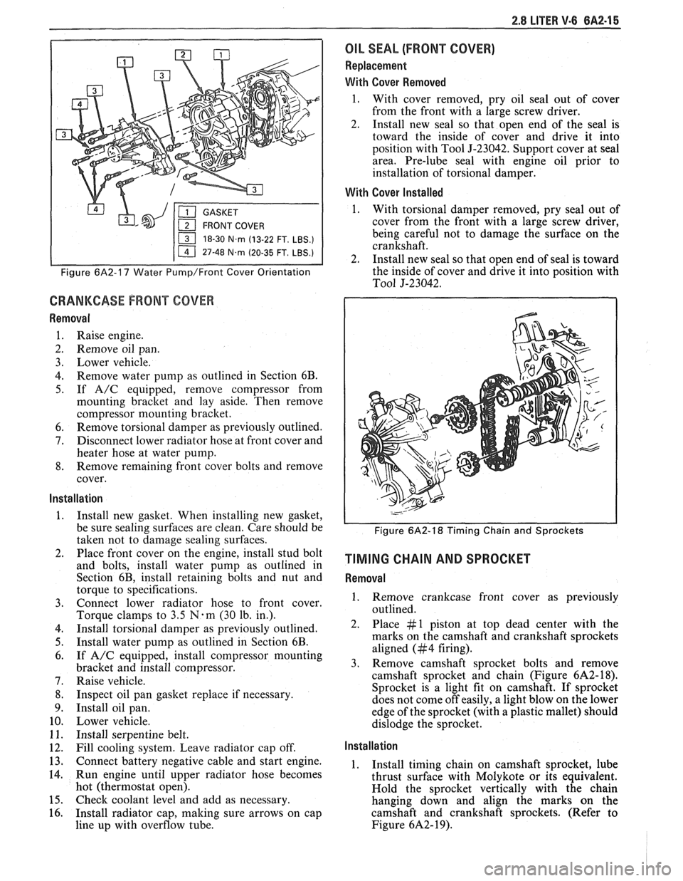
18-30 N.m (13-22 FT. LBS.)
I 11 47-48 N.m (20-35 FT. LBS.) I
Figure 6A2-17 Water Pump/Front Cover Orientation
CRANKCASE FRONT COVER
Removal
1. Raise engine.
2. Remove oil pan.
3. Lower vehicle.
4. Remove water pump as outlined in Section 6B.
5. If A/C equipped, remove compressor from
mounting bracket and lay aside. Then remove
compressor mounting bracket.
6. Remove torsional damper as previously outlined.
7. Disconnect lower radiator hose at front cover and
heater hose at water pump.
8. Remove remaining front cover bolts and remove
cover.
Installation
1. Install new gasket. When installing new gasket,
be sure sealing surfaces are clean. Care should be
taken not to damage sealing surfaces.
2. Place front cover on the engine, install stud bolt
and bolts, install water pump as outlined in
Section 6B, install retaining bolts and nut and
torque to specifications.
3. Connect lower radiator hose to front cover.
Torque clamps to
3.5 N-m (30 lb. in.).
4. Install torsional damper as previously outlined.
5. Install water pump as outlined in Section 6B.
6. If A/C equipped, install compressor mounting
bracket and install compressor.
7. Raise vehicle.
8. Inspect oil pan gasket replace if necessary.
9. Install oil pan.
10. Lower vehicle.
11. Install serpentine belt.
12. Fill cooling system. Leave radiator cap off.
13. Connect battery negative cable and start engine.
14. Run engine until upper radiator hose becomes
hot (thermostat open).
15. Check coolant level and add as necessary.
16. Install radiator cap, making sure arrows on cap
line up with overflow tube.
OIL SEAL (FRONT COVER)
Replacement
With Cover Removed
1. With cover removed, pry oil seal out of cover
from the front with a large screw driver.
2. Install new seal so that open end of the seal is
toward the inside of cover and drive it into
position with Tool
5-23042. Support cover at seal
area. Pre-lube seal with engine oil prior to
installation of torsional damper.
With Cover Installed
1. With torsional damper removed, pry seal out of
cover from the front with a large screw driver,
being careful not to damage the surface on the
crankshaft.
2. Install new seal so that open end of seal is toward
the inside of cover and drive it into position with
To01 5-23042.
Figure 6A2-18 Timing Chain and Sprockets
TIMING CHAIN AND SPROCKET
Removal
1. Remove crankcase front cover as previously
outlined.
2. Place #1 piston at top dead center with the
marks on the camshaft and crankshaft sprockets
aligned (#4 firing).
3. Remove camshaft sprocket bolts and remove
camshaft sprocket and chain (Figure
6A2- 18).
Sprocket is a light fit on camshaft.
If sprocket
does not come off easily, a light blow on the lower
edge of the sprocket (with a plastic mallet) should
dislodge the sprocket.
Installation
1. Install timing chain on camshaft sprocket, lube
thrust surface with Molykote or its equivalent.
Hold the sprocket vertically with the chain
hanging down and align the marks on the
camshaft and crankshaft sprockets. (Refer to
Figure
6A2- 19).
Page 370 of 1825
2.8 LITER V-6 6A2-19
4. Measure the crankpin for out-of-round or taper
with a micrometer. If not within specifications,
replace or recondition the crankshaft. If within
specifications and a new bearing is to be installed,
measure the maximum diameter of the crankpin,
to determine new bearing size required.
5. If within specifications, measure new or used
bearing clearance with Plastigage or its
equivalent.
NOTICE: If a bearing is being fitted to an
out-of-round crankpin, be sure to fit to the
maximum diameter of the crankpin. If the bearing
is fitted to the minimum diameter and the
crankpin is out-of-round .025mm interference
between the bearing and
crankpin will result in a
rapid bearing failure.
a.
Place a piece of gaging plastic the full width
of the
crankpin as contacted by the bearing
(parallel to the crankshaft).
b. Install
the bearing in the connecting rod and
cap.
c. Install
the rod cap and evenly torque nuts
to specifications. Do not turn the crankshaft
with gaging plastic installed.
d. Remove
the rod cap and using the scale on
the gaging plastic envelope, measure the
gaging plastic width at the widest point.
6. If
the clearance exceeds specifications, select a
new, correct size, bearing and remeasure the
clearance.
If clearance cannot be brought to within
specifications, the
crankpin will have to be
ground undersize. If the
crankpin is already
at maximum undersize, replace crankshaft.
7. Coat the
bearing surface with oil, install the rod
cap and torque nuts to 50
N-m (37 lb. ft.).
8. When all connecting rod bearings have been
installed tap each rod lightly (parallel to the
crankpin) to make sure they have clearance.
9. Measure all connecting rod side clearances (see
specifications) between the rod cap and
crankshaft throw (Figure 6A2-23).
MAIN BEARINGS (FIGURE 6A2-24)
Main bearings are of the precision insert type and
do not utilize shims for adjustment. If clearances are
found to be excessive, a new bearing, both upper and
lower halves, will be required. Service bearings are
available in standard size and undersize.
Selective fitting of both rod and main bearing
inserts is necessary in production in order to obtain
close tolerances. For this reason you may find one half
of a standard insert with one half of a
.016mm
undersize insert which will decrease the clearance
.008mm from using a full standard bearing.
Inspection
In general, the lower half of the bearing (except
# 1 bearing) shows a greater wear and the most distress
from fatigue. If upon inspection, the lower half is
suitable for use, it can be assumed that the upper half
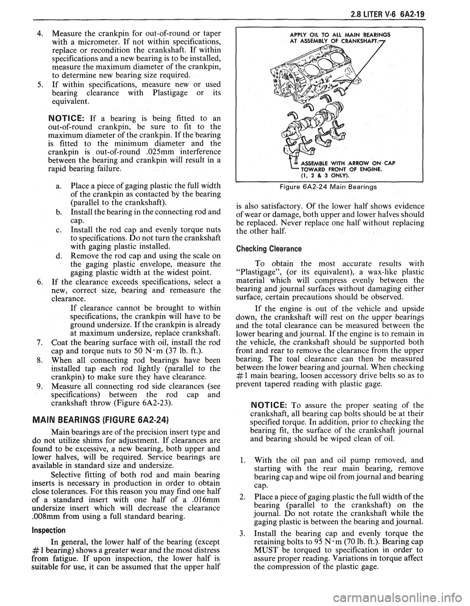
APPLY OIL TO ALL MAlN BEARINGS
E WITH ARROW ON CAP
FRONT OF ENGINE.
(1, 2 8, 3 ONLY).
Figure 6A2-24 Main Bearings
is also satisfactory. Of the lower half shows evidence
of wear or damage, both upper and lower halves should
be replaced. Never replace one half without replacing
the other half.
Checking Clearance
To obtain the most accurate results with
"Plastigage", (or its equivalent), a wax-like plastic
material which will compress evenly between the
bearing and journal surfaces without damaging either
surface, certain precautions should be observed.
If the engine is out of the vehicle and upside
down, the crankshaft will rest on the upper bearings
and the total clearance can be measured between the
lower bearing and journal. If the engine is to remain in
the vehicle, the crankshaft should be supported both
front and rear to remove the clearance from the upper
bearing. The toal clearance can then be measured
between the lower bearing and journal. When checking
# 1 main bearing, loosen accessory drive belts so as to
prevent tapered reading with plastic gage.
NOTICE: To assure the proper seating of the
crankshaft, all bearing cap bolts should be at their
specified torque. In addition, prior to checking the
bearing fit, the surface of the crankshaft journal
and bearing should be wiped clean of oil.
1. With the oil pan and oil pump removed, and
starting with the rear main bearing, remove
bearing cap and wipe oil from journal and bearing
cap.
2. Place a piece of gaging plastic the full width of the
bearing (parallel to the crankshaft) on the
journal. Do not rotate the crankshaft while the
gaging plastic is between the bearing and journal.
3. Install
the bearing cap and evenly torque the
retaining bolts to 95
N.m (70 lb. ft.). Bearing cap
MUST be torqued to specification in order to
assure proper reading. Variations in torque affect
the compression of the plastic gage.
Page 387 of 1825
6A3-8 V-8 ENGINE
10. Remove exhaust pipe nuts.
1 1. Lower vehicle.
12. Remove manifold bolts.
13. Remove manifold.
Installation
1. Clean mating surfaces on manifold and head,
then install manifold in position and install bolts
finger tight.
2. Torque bolts to specifications.
3. Reverse removal procedures.
4. Adjust necessary drive belts.
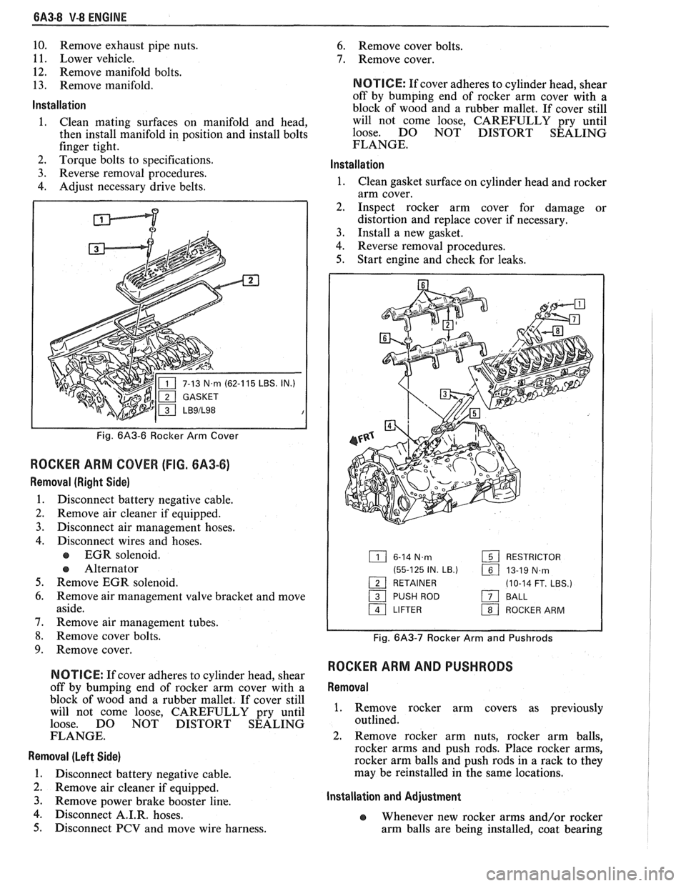
P
IN.)
Fig. 6A3-6 Rocker Arm Cover
ROCKER ARM COVER (FIG. 6A3-6)
Removal (Right Side)
1. Disconnect battery negative cable.
2. Remove air cleaner if equipped.
3. Disconnect air management hoses.
4. Disconnect wires and hoses.
EGR solenoid.
e Alternator
5. Remove EGR solenoid.
6. Remove air management valve bracket and move
aside.
7. Remove air management tubes.
8. Remove cover bolts.
9. Remove cover.
N OTI G E: If cover adheres to cylinder head, shear
off by bumping end of rocker arm cover with a
block of wood and a rubber mallet. If cover still
will not come loose, CAREFULLY pry until
loose. DO NOT DISTORT SEALING
FLANGE.
Removal (Left Side)
1. Disconnect battery negative cable.
2. Remove air cleaner if equipped.
3. Remove Power brake booster line.
4. isc connect A.I.R. hoses.
5. Disconnect PCV and move wire harness.
6. Remove cover bolts.
7. Remove cover.
NOTICE: If cover adheres to cylinder head, shear
off by bumping end of rocker arm cover with a
block of wood and a rubber mallet. If cover still
will not come loose, CAREFULLY pry until
loose. DO NOT DISTORT SEALING
FLANGE.
lnstallation
1. Clean gasket surface on cylinder head and rocker
arm cover.
2. Inspect rocker arm cover for damage or
distortion and replace cover if necessary.
3. Install a new gasket.
4. Reverse removal procedures.
5. Start engine and check for leaks.
6-14 N.m RESTRICTOR
(55-125 IN.
LB.) 161 13-19 N,rn - 1 RETAINER (10-14 FT. LBS.)
/ PUSH ROD a BALL
a LIFTER 1 ROCKER ARM
Fig. 6A3-7 Rocker Arm and Pushrods
ROCKER ARM AND PUSHRODS
Removal
1. Remove rocker arm covers as previously
outlined.
2. Remove rocker arm nuts, rocker arm balls,
rocker arms and push rods. Place rocker arms,
rocker arm balls and push rods in a rack to they
may be reinstalled in the same locations.
Installation and Adjustment
e Whenever new rocker arms and/or rocker
arm balls are being installed, coat bearing
Page 394 of 1825
V-8 ENGINE 6A3-15
engine to deliver the power and performance built into
it.
Another important factor is the cooling of the
valve heads. Good contact between each valve and its
seat in the head is imperative to insure that the heat in
the valve head will be properly carried away.
Several different types of equipment are available
for reseating valves seats. The recommendations of the
manufacturer of the equipment being used should be
carefully followed to attain proper results.
Regardless of what type of equipment is used,
however, it is essential that valve guide bores be free
from carbon or dirt to ensure proper centering of pilot
in the guide. Valve seats should be concentric to within
,002" total indicator reading.
VALVES
Valves that are pitted can be refaced to the proper
angle, insuring correct relation between the head and
stem on a valve
refacing mechanism. Valve stems
which show excessive wear, or valves that are warped
excessively should be replaced. When a valve head
which is warped excessively is
refaced, a knife edge will
be ground on part or all of the valve head due to the
amount of metal that must be removed to completely
reface. Knife edges lead to breakage, burning or
pre-ignition due to heat localizing on this knife edge.
If the edge of the valve head is less than 1/32"
(.08mm)
thick after grinding, replace the valve. Several different
types of equipment are available for
refacing valves.
The recommendation of the manufacturer of the
equipment being used should be carefully followed to
attain proper results.
TORSIONAL DAMPER
Removal
1.
Remove drive belts and pulley.
2. Raise vehicle.
3. Remove crankshaft pulley, then remove damper
retaining bolt.
4. Install Tool J-23523 on damper then, turning
puller screw, remove damper.
Installation
NOTICE: The inertial weight section of the
torsional damper is assembled to the hub with a
rubber type material. The installation procedures
(with proper tool) must be followed or movement
of the inertia weight section on the hub will
destroy the tuning of the torsional damper.
1. Inspect the cover seal contact area surface (on
damper) for damage or grooving and coat front
cover seal with engine oil.
2. Place damper in position over key on crankshaft.
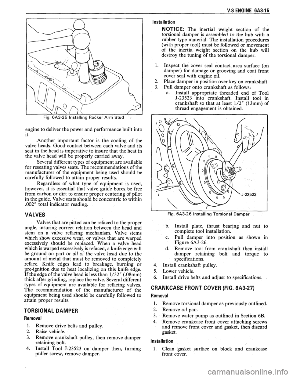
3. Pull damper onto crankshaft as follows:
a. Install appropriate threaded end of Tool
J-23523 into crankshaft. Install tool in
crankshaft so that at least
1/2" (13mm) of
thread engagement is obtained.
Fig. 6A3-26 Installing Torsional Damper
b.
Install plate, thrust bearing and nut to
complete tool installation.
c. Pull damper into position as shown in
Figure 6A3-26.
d. Remove tool from crankshaft then install
damper retaining bolt and torque to
specifications.
4. Install crankshaft pulley.
5. Lower vehicle.
6. Install drive belts and adjust to specifications.
CRANKCASE FRONT COVER (FIG. 6A3-27)
Removal
1.
Remove torsional damper as previously outlined.
2. Remove oil pan.
3. Remove water pump as outlined in Section
6B.
4. Remove crankcase front cover attaching screws
and remove front cover and gasket, then discard
gasket.
lnstallation
1. Clean gasket surface on block and crankcase
front cover.
Page 401 of 1825
BA3-22 V-8 ENGINE
5. On the edge of gaging plastic envelope there is a
graduated scale which is correlated in
thousandths of an inch. Without removing the
gaging plastic, measure its compressed width (at
the widest point) with the graduations on the
gaging plastic envelope (fig. 6A3-40).
Normally main bearing journals wear evenly and
are not out-of-round. However, if a bearing is
being fitted to an out-of-round journal
(.00lU
max.), be sure to fit to the maximum diameter of
the journal: If the bearing is fitted to the
minimum diameter and the journal is
out-of-round
.001", interference between the
bearing and journal will result in rapid bearing
failure. If the flattened gaging plastic tapers
toward the middle or ends, there is a difference
in clearance indicating taper, low spot or other
irregularity of the bearing or journal. Be sure to
measure the journal with a micrometer if the
flattened gaging plastic indicates more than
.00lV
difference.
6. If the bearing clearance is within specifications,
the bearing insert is satisfactory. If the clearance'
is not within specifications, replace the insert.
Always replace both upper and lower inserts as
a unit.
If a new bearing cap is being installed and
clearance is less than
.00 1 ", inspect for burrs or
nicks; if none are found then install shims as
required.
I MEASURE END PLAY
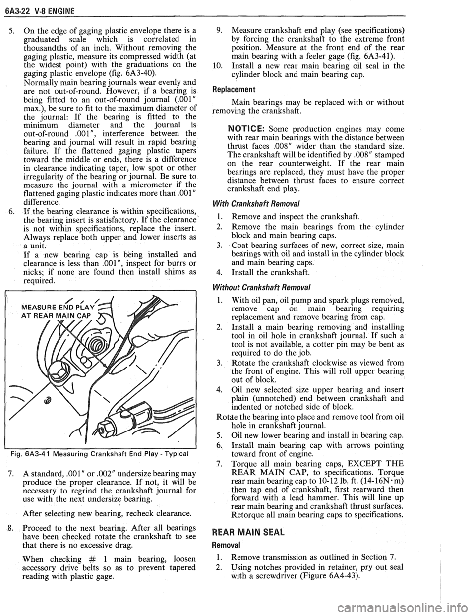
Fig. 6A3-4 1 Measuring Crankshaft End Play - Typical
7. A standard, .001" or .002" undersize bearing may
produce the proper clearance. If not, it will be
necessary to regrind the crankshaft journal for
use with the next undersize bearing.
After selecting new bearing, recheck clearance.
8. Proceed to the next bearing. After all bearings
have been checked rotate the crankshaft to see
that there is no excessive drag.
When checking
&t 1 main bearing, loosen
accessory drive belts so as to prevent tapered
reading with plastic gage.
9. Measure crankshaft end play (see specifications)
by forcing the crankshaft to the extreme front
position. Measure at the front end of the rear
main bearing with a feeler gage (fig.
61\3-41),
10. Install a new rear main bearing oil seal in the
cylinder block and main bearing cap.
Replacement
Main bearings may be replaced with or without
removing the crankshaft.
NOTICE: Some production engines may come
with rear main bearings with the distance between
thrust faces
,008" wider than the standard size.
The crankshaft will be identified by
,008" stamped
on the rear counterweight. If the rear main
bearings are replaced, they must have the proper
distance between thrust faces to ensure correct
crankshaft end play.
With Crankshaft Removal
1. Remove and inspect the crankshaft.
2. Remove the main bearings from the cylinder
block and main bearing caps.
3. Coat bearing surfaces of new, correct size, main
bearings with oil and install in the cylinder block
and main bearing caps.
4. Install the crankshaft.
Without Crankshaft Removal
1. With oil pan, oil pump and spark plugs removed,
remove cap on main bearing requiring
replacement and remove bearing from cap.
2. Install a
main bearing removing and installing
tool in oil hole in crankshaft journal. If such a
tool is not available, a cotter pin may be bent as
required to do the job.
3. Rotate the crankshaft clockwise as viewed from
the front of engine. This will roll upper bearing
out of block.
4. Oil new selected size upper bearing and insert
plain (unnotched) end between crankshaft and
indented or notched side of block.
Rot$e the bearing into place and remove tool from oil
hole in crankshaft journal.
5. Oil new lower bearing and install in bearing cap.
6. Install main bearing cap with arrows pointing
toward front of engine.
7. Torque all main bearing caps, EXCEPT THE
REAR MAIN CAP, to specifications. Torque
rear main bearing cap to 10- 12 lb. ft. (14-
16N. m)
then tap end of crankshaft, first rearward then
forward with a lead hammer. This will line up
rear main bearing and crankshaft thrust surfaces.
Retorque all main bearing caps to specifications.
REAR MAIN SEAL
Removal
1. Remove transmission as outlined in Section 7.
2. Using notches provided
in retainer, pry out seal
with a screwdriver (Figure 6A4-43).
Page 412 of 1825
ENGINE COOLING 6B-1
SECTION 6B
NE COOL
General Description ................................ 6B- 1 Off-Vehicle Leak Testing ............................... 6B-9
Radiator
...................................................... 6B- 1 Repairable Leaks ........................ ... .......... 6B- 10
Radiator Cap
......................... .. ............... 6B- 1 Repair Methods ................................................ 6B- 10
Recovery Bottle ......................................... 6B-2 Cooling Fin Removal ................................ 6B- 10 - ............................................. Fans ............................................................... 6B-2 Tube Blocking 6B- 1 1 ............ Header Repair ....................... .... 6B- 1 1 Temperature Switch ..................................... 6B-2 General Core Repair 6B- 1 1 ....................................
........................... Coolant Temperature Fan Switch ................ 6B-2 Tank
Gasket ~eik Repair 6B- 12
................... Thermostat .. 6B-3 Oil
Cooler Gasket Replacement
6B- 13 ............... ................................
...........................................................
Coolant Recovery System 6B-3 Recore 6B- 14 ............................. Special Tools ..................................................... 6B- 14 Diagnosis ..................................................... 6B-3
.............................. ..................................... Service Procedures 6B-3 On-Vehicle Service 6B-14
Cooling System Care
............................... 6B-3 Thermostat ....................................... 6B-14
Draining and Refilling the Cooling Electric Cooling Fan ............................. 6B-15
System
................................................... 6B-7 Water Pump .................... .... ......... 6B-15
Drive Belt
...................... .. .......................... 6B-7 Coolant Recovery Bottle ........................ 6B-16
.......................................... Aluminum Radiator Service .................... 6B-8 Radiator 6B-17
Diagnosis .................................................... 6B-8
Leak Testing
.............................................. 6B-8
On-Vehicle Pressure Testing
...................... .... 6B-9
GENERAL DESCRIPnIBN
The cooling system maintains engine temperature
5" below the filler neck which reads, "Important - for
at an efficient level during all engine operating repair see Harrison Service Manual". Service
conditions. When the engine is cold the system cools procedures for the aluminum plastic radiator are
slowly, or not at all, to allow the engine to warm up described in that manual and in this section.
quickly.
The cooling system includes a radiator and
Radiator Cap
recovery sub-system, cooling fan, thermostat and
housing, water pump, and drive belts.
Operation of the cooling system requires proper
functioning of all components. Coolant is drawn from
the radiator by the water pump and circulated through
water jackets in the engine block, intake manifold, and
cylinder
head(s), and then directed back to the radiator
where it's cooled.
This system directs some coolant through hoses
to the heater core, to provide for heating and
defrosting. A recovery bottle is connected to the
radiator to recover coolant displaced by expansion
from high temperatures and maintain correct coolant
level. As the coolant cools and contracts it is drawn
back into the radiator by vacuum.
RADIATOR
A cross-flow radiator is used on all models. Tanks
in this type radiator are located to the right and left of
the core, instead of above and below.
Radiators used with automatic transmissions
have oil coolers with inlet and outlet fittings for
transmission fluid circulation. Cars with manual
transmissions use radiators without oil coolers.
Vehicles equipped with air conditioning use a radiator
with extra cooling capability.
An aluminum-plastic radiator, used on some
models, can be identified by a note on the outlet tank A pressure-vent
cap is used on the cross-flow
radiator to allow a buildup of
103 kPa (15 psi) in the
cooling system. This pressure raises the boiling point
of coolant to approximately 125°C (262°F) at sea level.
Do not remove radiator cap to check engine
coolant level; check coolant visually at the
see-through coolant reservoir. Coolant should
be added only
to the reservoir.
CAUTION: As long as there
is
pressure in the cooling system, the
temperature can be considerably
higher than the boiling temperature
of
the solution in the radiator without
causing the solution to boil. Removal
of the radiator cap while engine is hot
and pressure is high will cause
the
solution to boil instantaneously and
possibly with explosive
force, spewing
the solution over engine, fenders and
person removing cap. If the solution
contains flammable antifreeze, such
as alcohol (not recommended for use
at any time), there is also the
possibility
of causing a serious fire.
The pressure-type radiator filler cap contains a
blow off or pressure valve and a vacuum or
atmospheric valve (Figure
1). The pressure valve is
held against its seat by a spring of pre-determined
Page 418 of 1825
ENGINE COOLING BB-7
NOTICE: If recommended quality antifreeze is
used, supplemental inhibitors or additives claiming
to provide increased cooling capability are not
necessary. They may be detrimental to the efficient
operation of the system, and represent an
unnecessary operating expense.
Every 12 months or 15,000 miles, the cooling
system should be serviced as follows;
1. Wash radiator cap and filler neck with clean
water.
2. Check coolant for proper level and freeze
protection.
3. Pressure test system and radiator cap for proper
pressure holding capacity, 103
kPa (15 psi). If
replacement of cap is required, use the proper cap
specified for car model.
4. Tighten hose clamps and inspect all hoses. Replace
hoses whenever cracked, swollen or otherwise
deteriorated.
5. Clean frontal area of radiator core and air
conditioning condenser.
DRAINING AND REFILLING THE COOLING
SYSTEM
Replace hoses every 24 months or 30,000 miles or
earlier if cracked, swollen or otherwise deteriorated.
Every two years or 30,000 miles, whichever first
occurs, the cooling system should be flushed and
refilled using the following recommended procedure:
1. Remove radiator cap, or thermostat housing cap
(VIN
0, J, R and U), when engine is cool by:
a. Slowly
rotating cap counterclockwise to
detent. (Do not press down while rotating.)
b. Wait until any
residual pressure (indicated
by a hissing sound) is relieved.
c. After all hissing ceases, press down on cap
while continuing to rotate
counterclockwise.
CAUTION: To avoid the danger of
being burned, do not remove radiator
cap while engine and radiator are still
hot. Scalding fluid and steam may be
blown out under pressure.
2. Remove the thermostat by using the wire handle
to lift it out of the housing (VIN
0, J, R and U).
3. With the thermostat removed, reinstall the
thermostat housing cap (VIN
0, J, R and U).
4. Open radiator drain valve and block drain plugs
to drain coolant. On VIN R and
9 (P series)
engines, open coolant pipe plugs.
5. Close valve. Reinstall drain plugs, and add
sufficient water to fill system.
6. Run engine, drain and refill the system, as
described in steps
4 and 5 a sufficient number of
times, until the drained liquid is nearly colorless.
Important
BLOCK DRIVE WHEELS, place
transmission in PARK (automatic
transmission) or NEUTRAL (manual
transmission) and set the parking brake. 7.
Allow system to drain completely. Then close
radiator drain valve tightly, and reinstall block
drain plugs.
8. Remove recovery cap leaving hoses in place.
Remove coolant recovery tank and empty of
fluid. Flush tank with clean water, drain and
reinstall.
9. Add sufficient ethylene glycol coolant, meeting
GM specification 1825-M, to provide the
required freezing and corrosion protection
- at
least 50 percent solution -37°C (-34°F). Fill
radiator to the base of the radiator fill neck and
add sufficient coolant to the recovery tank to
raise level to the "FULL" mark. Reinstall
recovery tank cap.
10. Run engine, with radiator cap or thermostat
housing cap removed, until normal operating
temperature is reached. (Radiator upper hose
becomes hot.)
11. With engine idling, add coolant until level
reaches bottom of filler neck and reinstall cap,
making certain arrows line up with overflow tube.
CAUTION: Under some conditions, the
ethylene glycol in engine coolant is
flammable. To help avoid being
burned when adding coolant, DO NOT
spill
it on the exhaust system or hat
engine parts.
It is the owner's responsibility to keep the freeze
protection at a level appropriate to the
temperatures which may occur in the area of
vehicle operation.
a. Maintain
cooling system freeze protection
at
-37°C (-34"F), to ensure protection
against corrosion and loss of coolant from
boiling, even though freezing temperatures
are not expected.
b. Add ethylene glycol base coolant that meets
GM Specification 1825-M, when coolant
additions are required because of coolant
loss, or to provide additional protection
against
freezing at temperatures lower than
-37°C (-34°F).
NOTICE: Alcohol or methanol base coolants, or
plain water, are not recommended at any time.
DRlVE BELT
NOTICE: Routine inspection of the belt may
reveal cracks in the belt ribs. These cracks will
not impair belt performance and therefore should
not be considered a problem requiring belt
replacement. However, the belt should be
replaced if belt slip occurs or if sections of the
belt ribs are missing.
A single (serpentine) belt is used to drive all
engine accessories formerly driven by multiple drive
belts. All belt driven accessories are ridgedly mounted
with belt tension maintained by a spring loaded
tensioner.
The drive belt tensioner has the ability to control
belt tension over a fairly broad range of belt lengths.
Page 419 of 1825
68-8 ENGINE COOLING
However, there are limits to the tensioner's ability to
The tensioner has rovisions for a visual check to
compensate for varying lengths of belts. With the
ten- verify that it is in t e "operating range" (see Figures
sioner outside of its operating range, poor tension
608 and 609). R
control andlor damage to the tensioner may result.
ALUMINUM RADIATOR REPAIR
This radiator utilizes an aluminum core with
plastic side tanks. The core and side tanks can be
replaced separately and core repair is easily made with
the hot melt adhesive method. A transaxle oil cooler
is located in one of the side tanks. The oil cooler can
be replaced. The drain cock is located on the lower part
of one of the tanks. The drain cock is also serviceable.
Core
The core is made of aluminum and is of the
crossflow design. It utilizes large tubes that resist
plugging, and repairs to the tubes and core are easily
made using the hot melt adhesive method.
The core is attached to the tanks by clinched tabs
on the core that can be bent back if tank or core
replacement is required.
If the damage to a tube is too severe, a tube can
be blocked or plugged as explained in "Tube Blocking.
" No more than two tubes should ever be blocked on
a core. Also replace the core if more than three tabs are
broken on one side, or if two adjacent tabs are broken.
Tanks
The tanks are attached to the core by the use of
clinched tabs. The clinched tabs can be bent back if the
tanks need to be removed from the core. Bend the tabs
back only enough to remove the tank. Overbending
will weaken the tabs.
A high temperature rubber gasket is used to seal
the mating surface between the core and the tank. (See
Fig. 8). The gasket must be replaced any time a tank
is removed from the core.
Transaxle Oil Cooler
The transaxle oil cooler is located in one of the
radiator side tanks. The oil cooler can be replaced by
removing the tank from the core.
A leaking oil cooler gasket can be replaced
without removing the tank from the core.
Drain Cock
The aluminum/plastic radiator utilizes a two
piece plastic drain cock and a rubber seal. The drain
cock is serviceable (See Fig.
9).
ALUMINUM RADIATOR SERVICE
The aluminum-plastic radiator can be repaired at
the dealership. The following components are easily
replaced:
e Core
e Tanks and gaskets
o Oil coolers and gaskets
e Drain cock and gasket The
tanks cannot be repaired if broken or
cracked. The radiator core can be replaced and the new
core used with the original tanks and oil cooler.
Precautions
As with all cooling system service, take measures
to prevent personal injury and damage to the system.
CAUTION: To help avoid the danger of
being burned, do not remove the
radiator cap while the engine and
radiator are
still hot. Scalding fluid
and steam can be blown out under
pressure if the
cap is taken off too
soon.
NOTICE: DO NOT USE "BOIL OUT" TANKS
OR VATS. Common service methods may
actually destroy an aluminum radiator. Caustic or
lye cleaning solutions must NOT be used for
aluminum radiators.
e Do not open the hood if you can see, or hear,
steam or coolant escaping from the engine
compartment.
e Do not remove radiator cap if radiator feels
warm.
e Do not remove the radiator cap or coolant
recovery tank cap if the coolant in the recovery
tank looks like it is boiling.
Wear eye protection.
e Wear gloves to protect your hands against
excessive heat, or the effects of chemicals on your
skin.
o Prevent dirt and water from entering the
transmission oil cooler.
e Do not use boil-out tanks, or vats, or other tanks
that have been used for copper and brass
radiators. The flux, acid, and caustic cleaners
remaining in these tanks will attack the
aluminum and cause radiator failure.
A separate
test tank containing clean water is strongly
recommended for servicing aluminum-plastic
radiators.
RIOTICE: Never use shop air that is not regulated
at
20 psi (138 kPa) to pressure test radiator.
Pressures over
20 psi (138 kPa) will damage the
radiator.
DIAGNOSIS
Leak Testing
Some core leaks can be detected by merely adding
water to the radiator. It is helpful to clean the core so
that the damaged area can be more easily found.