1988 PONTIAC FIERO belt
[x] Cancel search: beltPage 84 of 1825
R-4 AIR CONDITIONING COMPRESSOR - OVERHAUL 1 Dl-5
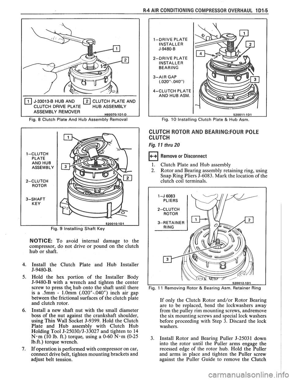
J-33013-8 HUB AND CLUTCH PLATE AND
CLUTCH DRIVE PLATE HUB ASSEMBLY
ASSEMBLY REMOVER
H60070-1 Dl-D
Fig. 8 Clutch Plate And Hub Assembly Removal
1-CLUTCH PLATE AND HUB
ASSEMBLY
2-CLUTCH ROTOR
3-SHAFT KEY
Fig.
9 Installing Shaft Key
NOTICE: To avoid internal damage to the
compressor, do not drive or pound on the clutch
hub or shaft.
4. Install the Clutch Plate and Hub Installer
J-9480-B.
5. Hold the hex portion of the Installer Body
J-9480-B with a wrench and tighten the center
screw to press the, hub onto the shaft until there
is
a .5mm - l.Omm (.020"-.040") inch air gap
between the frictional surfaces of the clutch plate
and clutch rotor.
6. Install a new shaft nut with the small diameter
boss of the nut against the crankshaft shoulder,
using Thin Wall Socket J-9399. Hold the Clutch
Plate and Hub assembly with Clutch Hub
Holding Tool
J-25030/J-33027 and tighten to 14
N-m (10 lb. ft.) torque, using a 0-60 N-m (0-25
1b.ft.) torque wrench.
7. If operation is performed with compressor on car,
connect drive belt, tighten mounting brackets and
adjust belt tension.
1-DRIVE PLATE
INSTALLER
J-9480-B
2-DRIVE PLATE
INSTALLER
BEARING
3-AIR GAP
(.02OU-.040")
4-CLUTCH PLATE
AND HUB ASM.
Fig.
10 Installing Clutch Plate & Hub Asm.
CLUTCH ROTOR AND BEARING:FOUR POLE
CLUTCH
Fig. 11 thru 28
Remove or Disconnect
1. Clutch Plate and Hub assembly
2. Rotor and Bearing assembly retaining ring, using
Snap Ring Pliers J-6083. Mark the location of the
clutch coil terminals.
Fig. 11 Removing Rotor & Bearing Asm. Retainer Ring
If only the Clutch Rotor and/or Rotor Bearing
are to be replaced, bend the lockwashers away
from the pulley rim mounting screws, andremove
the six mounting screws and special lock washers
before proceeding with Step 3. Discard the lock
washers.
3. Install Rotor and Bearing Puller
5-25031 down
into the rotor until the Puller arms engage the
recessed edge of the rotor hub. Hold the Puller
and arms in place and tighten the Puller screw
against the Puller Guide to remove the Clutch
Page 89 of 1825
1191-"1 8-4 AIR CONDITIONING COMPRESSOR OVERHAL
CLUTCH COIL AND PULLEY RIM
Fig. 29 thru 34
Clutch coil and pulley rim installation
and removal procedures for the six-pole
clutch are the same as the four-pole clutch
with the exception of Steps
1 through 4 of
the
clutch rotor and/or bearing - Six-Pole
Clutch, removal or disconnect must
be used.
V-Groove Drive
Remove
or Disconnect
1. Perform Steps I through 4 of CLUTCH ROTOR
AND BEARING removal procedure but do not
loosen or remove the pulley rim mounting screws
until the Clutch Rotor, Coil and Pulley Rim
assembly have been removed from the Front
Head. Be careful not to drop the Puller Guide
5-2503 1 when removing the assembly.
2. Remove the pulley rim mounting screws and
special lock washers. Discard the lock washers
and screws.
3. Slide the pulley rim off the Rotor and Hub
assembly. The Pulley Rim and the Clutch Coil
are replaceable at this point.
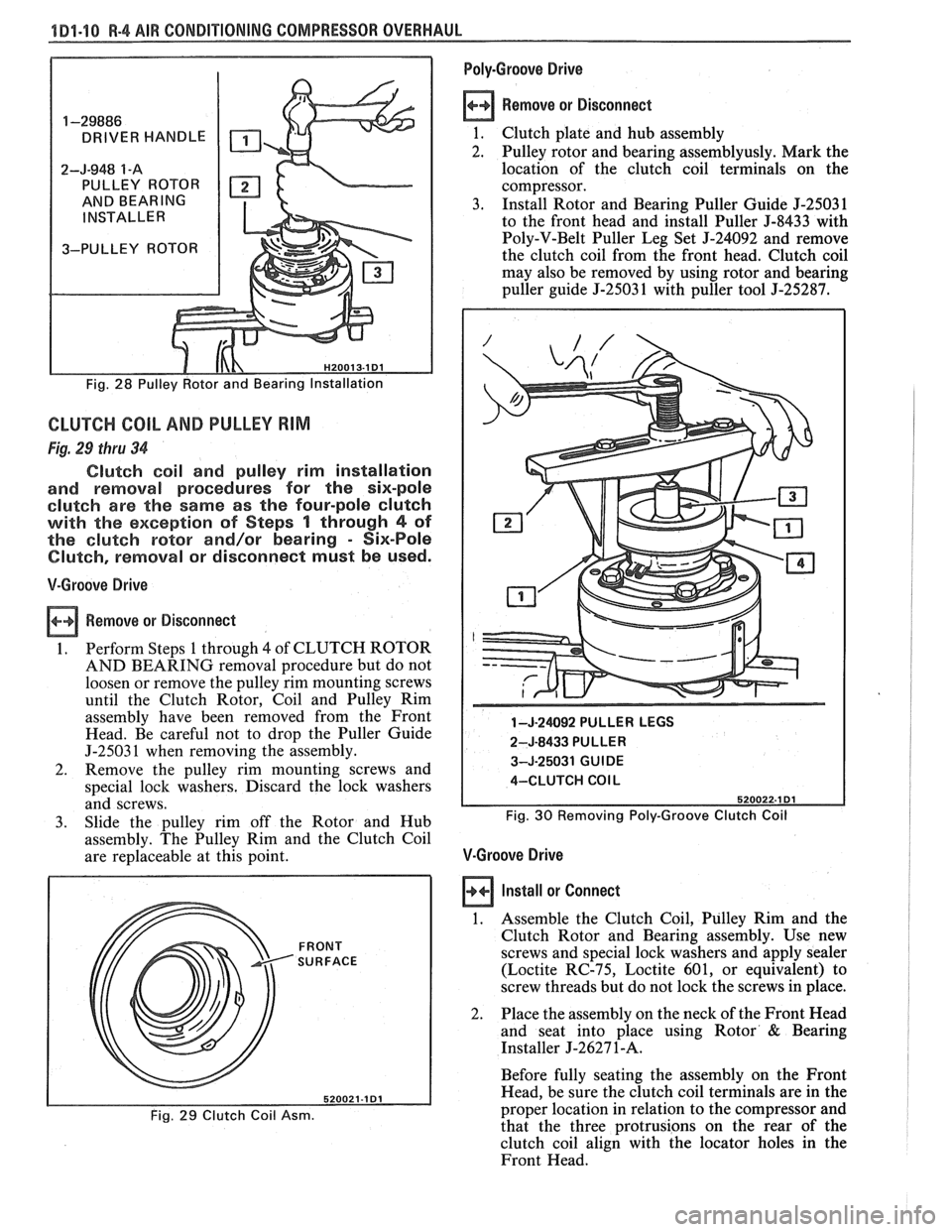
FRONT SURFACE
Fig. 29 Clutch Coil Asm.
Poly-Groove Drive
Remove
or Disconnect
1. Clutch plate and hub assembly
2. Pulley rotor and bearing assemblyusly. Mark the
location of the clutch coil terminals on the
compressor.
3. Install Rotor and Bearing Puller Guide J-25031
to the front head and install Puller J-8433 with
Poly-V-Belt Puller Leg Set
5-24092 and remove
the clutch coil from the front head. Clutch coil
may also be removed by using rotor and bearing
puller guide
J-25031 with puller tool J-25287.
1 -J-24092 PULLER LEGS
2-J-8433 PULLER
3-J-25031 GUIDE
4-CLUTCH
COl L
Fig.
30 Removing Poly-Groove Clutch Coil
V-Groove Drive
Install or Connect
1. Assemble the Clutch Coil, Pulley Rim and the
Clutch Rotor and Bearing assembly. Use new
screws and special lock washers and apply sealer
(Loctite RC-75, Loctite
601, or equivalent) to
screw threads but do not lock the screws in place.
2. Place the assembly on the neck of the Front Head
and seat into place using Rotor
& Bearing
Installer
J-2627 1-A.
Before fully seating the assembly on the Front
Head, be sure the clutch coil terminals are in the
proper location in relation to the compressor and
that the three protrusions on the rear of the
clutch coil align with the locator holes in the
Front Head.
Page 92 of 1825
R-4 AIR CONDITIONING COMPRESSOR OVERHAUL 101-13.
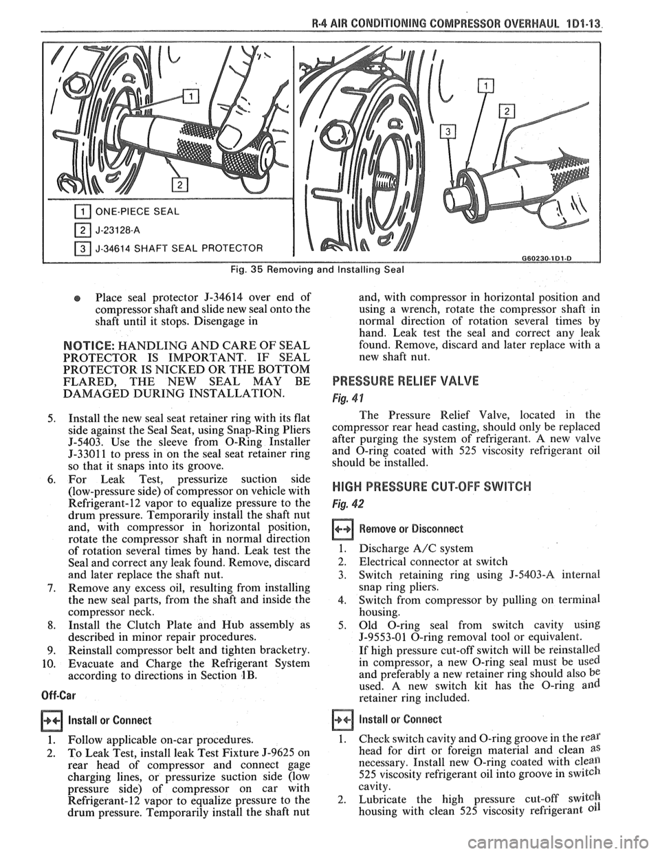
ONE-PIECE SEAL
J-34614 SHAFT SEAL PROTECTOR I G60230-181.8
Fig. 35 Removing and Installing Seal
Place seal protector 9-34614 over end of
compressor shaft and slide new seal onto the
shaft until it stops. Disengage in
NOTICE: HANDLING AND CARE OF SEAL
PROTECTOR IS IMPORTANT. IF SEAL
PROTECTOR IS NICKED OR THE BOTTOM
FLARED, THE NEW SEAL
MAY BE
DAMAGED DURING INSTALLATION.
5. Install the new seal seat retainer ring with its flat
side against the Seal Seat, using Snap-Ring Pliers
5-5403. Use the sleeve from O-Ring Installer
5-3301 1 to press in on the seal seat retainer ring
so that it snaps into its groove.
6. For Leak Test, pressurize suction side
(low-pressure side) of compressor on vehicle with
Refrigerant-12 vapor to equalize pressure to the
drum pressure. Temporarily install the shaft nut
and, with compressor in horizontal position,
rotate the compressor shaft in normal direction
of rotation several times by hand. Leak test the
Seal and correct any leak found. Remove, discard
and later replace the shaft nut.
7. Remove any excess oil, resulting from installing
the new seal parts, from the shaft and inside the
compressor neck.
8. Install the Clutch Plate and Hub assembly as
described in minor repair procedures.
9. Reinstall compressor belt and tighten bracketry.
10. Evacuate and Charge the Refrigerant System
according to directions in Section
1B.
Off-Car
Install or
Connect
1. Follow applicable on-car procedures.
2. To Leak Test, install leak Test Fixture 5-9625 on
rear head of compressor and connect gage
charging lines, or pressurize suction side (low
pressure side) of compressor on car with
Refrigerant-12 vapor to equalize pressure to the
drum pressure. Temporarily install the shaft nut and,
with compressor in horizontal position and
using a wrench, rotate the compressor shaft in
normal direction of rotation several times by
hand.
Leak test the seal and correct any leak
found. Remove, discard and later replace with a
new shaft nut.
PRESSURE RELIEF VALVE
Fig. 4 1
The Pressure Relief Valve, located in the
compressor rear head casting, should only be replaced
after purging the system of refrigerant,
A new valve
and O-ring coated with 525 viscosity refrigerant oil
should be installed.
HIGH PRESSURE CUT-OFF SWITCH
Fig. 42
Remove or Disconnect
1. Discharge A/C system
2. Electrical connector at switch
3. Switch retaining ring using
J-5403-A internal
snap ring pliers.
4. Switch from compressor by pulling on terminal
housing.
5. Old O-ring seal from switch cavity using
J-9553-01 O-ring removal tool or equivalent.
If high pressure cut-off switch will be reinstalled.
in compressor, a new O-ring seal must be
used
and preferably a new retainer ring should also be
used. A new switch kit has the O-ring and
retainer ring included.
install or Connect
1.
Check switch cavity and O-ring groove in the rear
head for dirt or foreign material and clean as
necessary. Install new O-ring coated with cleall
525 viscosity refrigerant oil into groove in switch
cavity.
2. Lubricate the high pressure cut-off
switgh
housing with clean 525 viscosity refrigerant
Page 126 of 1825
STEERING, SUSPENSION, f IRES AND WHEELS DIAGNOSIS 3.1
SECVION 3
STEER NG, SUSPENS
WHEELS
AGNOS
CONTENTS
........................................... General Information 3- 1 ............................................ General Diagnosis 3- 1
Power Recirculating Ball .................................. 3-3
................. Steering Linkage ........................ .. 3-3
Power Steering Pump ................... ... ............ 3-4
Steering Column
Lock System
........................... ... ................ 3-4
Column ............................................................ 3-5
........................................ Turn Signal Switch 3-6
Ignition Switch .............................................. 3-7
Key Reminder .............................................. 3-7
Dimmer Switch .................... ... ................ 3-10
Pivot and Switch Assembly ............................ 3-10
Steering Gear and Pump Leaks .......................... 3- 10
Seal Replacement Recommendations ................. 3- 10
Power Steering System Test Procedure .............. 3-12
................ Strut Dampener and Shock Absorber 3- 12
Tires ........................ .. ..................................... 3- 13
Vibrations .......................... .............. .................... 3- 14
.......................... Tapered Roller Bearings .. .... 3- 14
Trim Height .............................................. 3-14
GENERAL INFORMATION Abnormal or Excessive Tire Wear
Since the problems in steering, suspension, tires
and wheels involve several systems, they must all be
considered when diagnosing a complaint. To avoid
e Front-wheel or rear-wheel alignment
using the wrong symptom, always road test the car
o Sagging or broken springs
first. Proceed with the following preliminary checks
Tire out of balance and correct any substandard conditions which are worn strut dampener or shock absorber found. o Hard driving
--
e Tires for wrong pressure and uneven wear
o Joints from the column to the steering gear for
loose connectors or wear
o Front and rear suspension, and the steering gear
or linkage for loose or damaged parts
Out-of-round or out-of-balance tires, bent wheels,
and loose and/or rough wheel bearings
@ Power steering system for leaks. Also check the
power steering fluid level and the pump drive belt
tension
GENERAL DIAGNOSIS
Car Pulls (Leads)
Inspect
Mismatched or uneven tires
Broken or sagging springs
Radial tire lateral force
Front-wheel or rear-wheel alignment
o Steering gear valve off center (unbalanced)
e Front brakes dragging
a Overloaded car
e Not rotating tires
Scuffed Tires
o Toe incorrect
e Excessive speed on turns
o Suspension arm bent or twisted
Wheel Tramp
Inspect
o Blister or bump on tire
o Improper strut dampener or shock absorber
action
Shimmy, Shake or Vibration
inspect
e Tire or wheel out of balance
e Worn wheel bearings
a Worn tie rod ends
o Worn lower ball joints
Page 128 of 1825
STEERING, SUSPENSION, VIBES AND WHEELS DIAGNOSIS 3-3
Steering Wheel Kick-Back (Power)
Inspect
e Air in system
e Loose steering gear mounting
e Joints from column to steering gear loose or worn
e Tie rod ends loose
Worn or missing check valve
(800 series)
e Wheel bearings worn
e See "Too Much Play In Steering" for other
possible causes.
Steering Wheel Surges Or Jerks (Power)
Inspect
Hydraulic system - Make pressure test with gage
J 5176-D or
J 25323
e Sluggish steering gear valve
Loose pump drive belt
Cupped Tires
Inspect
Front-wheel or rear-wheel alignment
e Strut dampeners or shock absorbers weak
e Wheel bearing worn
e Excessive tire or wheel runout
e Worn ball joint
a Loose steering gear adjustment
POWER RECIRCULATING BALL
SEERING GEAR DIAGNOSIS
Hissing Noise
There is some noise in all power steering systems.
One of the most common is a hissing sound when the
steering wheel is turned and the car is not moving. This
noise will be most evident when turning the wheel
while the brakes are applied. There is no relationship
between this noise and steering performance. Do not
replace the valve unless the "hissing" noise is extremely
objectionable. A replacement valve will also have a
slight noise, and is not always a cure for the condition.
Check that the intermediate shaft joints are not loose.
Rattle or Chucking Noise
Inspect -
Pressure hose grounding out
e Tie rod ends loose
e Steering gear attachment loose
a Loose pitman shaft "over-center" adjustment.
A slight rattle may occur on turns because of
increased clearance off the "high point". This is
normal and clearance must not be reduced below
specified limits to eliminate this slight rattle.
Poor Return of Steering Wheel to Center
Front-wheel alignment
Wheel bearing worn
Tie rod end binding
Ball joint binding
Steering wheel rubbing against turn signal
housing
Steering gear adjustments
Tight or frozen intermediate steering shaft
Sticky or plugged spool valve
Momentary Increase in Effort Whsn Turning
Wheel Fast to Right or Left
Inspect
High internal leakage
Steering Wheel Surges or Jerks When Turning
With
Engine Running Especially During Parking
ln8pe~t
e Insufficient pump pressure
Sticky flow control valve
Excessive Wheel Kickback or Loose Steering
Air in system
Steering gear attachment loose
Tie rod ends loose
Wheel bearings worn
Steering gear flexible coupling loose on shaft or
rubber disc mounting nuts loose
Loose thrust bearing preload adjustment
Excessive "over-center" lash
Worn pressure port check valve
Hard Steering or Lack of Assist
(Especially During Parking)
-
Brakes applied while turning steering wheel
Intermediate shaft damaged or worn
e Sticky flow control valve
Insufficient pump pressure
Excessive internal pump leakage
Excessive internal steering gear leakage
STEERING LINKAGE DIAGNOSIS
Excessive Play or Looseness in Steering Systern
inspect
r, Worn upper ball joints
e Steering gear worm bearings loosely adjusted
Page 139 of 1825
3-14 STEERING, SUSPENSION, TIRES AND WHEELS DIAGNOSIS
@ HARD CORNERING O UNDER INFLATION LACK OF ROTATION
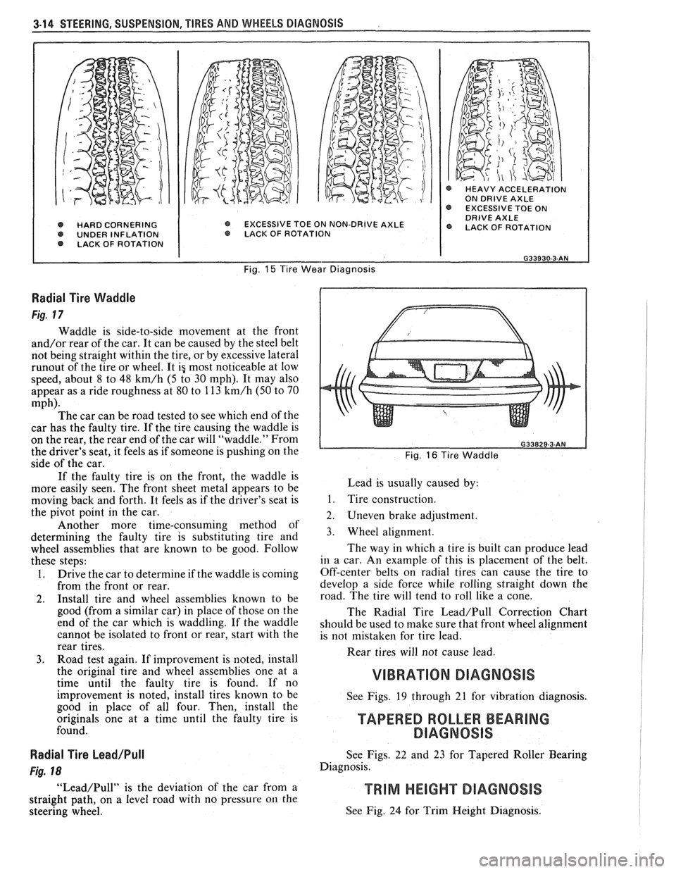
@ HEAVY ACCELERATION ON DRIVE AXLE EXCESSIVE TOE ON DRIVE AXLE EXCESSIVE TOE ON NON-DRIVE AXLE @ LACK OF ROTATION O LACK. OF ROTAT ION
Fig. 15 Tire Wear Diagnosis
Radial Tire Waddle
Fig. 17
Waddle is side-to-side movement at the front
and/or rear of the car. It can be caused by the steel belt
not being straight within the tire, or by excessive lateral
runout of the tire or wheel. It ig most noticeable at low
speed, about 8 to 48
km/h (5 to 30 mph). It may also
appear as a ride roughness at 80 to 113
km/h (50 to 70
mph). The car can be road tested to see which end of the
car has the faulty tire. If the tire causing the waddle is
on the rear, the rear end of the car will "waddle." From
the driver's seat, it feels as if someone is pushing on the
side of the car.
If the faulty tire is on the front, the waddle is
more easily seen. The front sheet metal appears to be
moving back and forth. It feels as if the driver's seat is
the pivot point in the car.
Another more time-consuming method of
determining the faulty tire is substituting tire and
wheel assemblies that are known to be good. Follow
these steps:
1. Drive the car to determine if the waddle is coming
from the front or rear.
2. Install tire and wheel assemblies known to be
good (from a similar car) in place of those on the
end of the car which is waddling. If the waddle
cannot be isolated to front or rear, start with the
rear tires.
3. Road test again. If improvement is noted, install
the original tire and wheel assemblies one at a
time until the faulty tire is found. If no
improvement is noted, install tires known to be
good in place of all four. Then, install the
originals one at a time until the faulty tire is
found.
Radial Tire Lead/Pull
Fig. 18
"Lead/Pull" is the deviation of the car from a
straight path, on a level road with no pressure
on the
steering wheel.
L Fig. 16 Tire Waddle
Lead is usually caused by:
1. Tire construction.
2. Uneven brake adjustment.
3. Wheel alignment.
The way in which a tire is built can produce lead
in a car. An example of this is placement of the belt.
Off-center belts on radial tires can cause the tire to
develop a side force while rolling straight down the
road. The tire will tend to roll like a cone.
The Radial Tire
Lead/Pull Correction Chart
should be used to make sure that front wheel alignment
is not mistaken for tire lead.
Rear tires will not cause lead.
VIBRATION DIAGNOSIS
See Figs. 19 through 21 for vibration diagnosis.
TAPERED ROLLER BEARING
DlAGNOSlS
See Figs. 22 and 23 for Tapered Roller Bearing
Diagnosis.
See Fig. 24 for Trim Height Diagnosis.
Page 194 of 1825
POWER Sf EERING 387-1
SECTION 3B7
POWER STEER NG GEAR AND PUMP
The following notice applies to one or more steps in the assembly procedure of components in this portion
of the manual as indicated at appropriate locations. "See Notice on Page
1 of this Section".
NOTICE: Steering column fasteners are important attaching parts in that they may affect the performance
of vital components and systems, and/or could result in major repair expense. They must be replaced with one
of the same part number or with an equivalent part if replacement becomes necessary. Do not use a replacement
part of lesser quality or substitute design. Torque values must be used as specified during reassembly to assure
proper retention of these parts. For prevailing torque
nut(s) and bolt(s), refer to the "Reuse of Prevailing Torque
Nut(s) and Bolt(s)" chart in Section 10.
CONTENTS
MAINTENANCE AND ADJUSTMENTS
Bleeding Hydraulic System
................................................................................................. 3B7- 1
Fluid Level ......................................................................................................................... 3B7- 1
Power Steering Gear Adj. ..................................................................................................... 3B7- 1
Drive Belt Tension .............................................................................................................. 3B7-2
Hydraulic System Checks .................................................................................................. 3B7-2
Hydraulic System Test ......................................................................................................... 3B7-2
ON-VEHICLE SERVICE
Steering Gear Removal
...................................................................................................... 3B7-3
Pitman Shaft Seal .................................................................................................................. 3B7-3
Pump Removal ..... , ................................................................................................................ 3B7-4
................................................................................................................... Hoses and Pipes 3B7-4
Pump Pulley ....................................................................................................................... 3B7-4
.................................................................................. Pump Brackets/Hoses/Cooling Pipes 3B7-5
........................................................................................ Pump Overhaul .................... ..... 3B7- 12
Gear Overhaul .................................................................................................................... 3B7- 13
SPECIAL TOOLS ............................................................................................................ 3B7-17 ......................... .......................................................... GENERAL SPECIFICATIONS .. 3B7- 18
MAlNKNANGE AND ADJUSTMENTS
BLEEDING HYDRAULIC SYSTEM
Fill fluid reservoir to proper level and let remain
undisturbed for at least two minutes.
Start engine and run momentarily.
Shut engine off to add fluid.
Repeat above procedure until fluid level remains
constant after running engine.
Raise front end of vehicle so that wheels are off
the ground.
Start engine and increase engine speed to
approximately
1500 rpm.
Turn the wheels (off ground) right and left,
lightly contacting the wheel stops.
Lower the car and turn wheels right and left on
the ground.
Shut engine off, check fluid level and refill as
required.
If fluid is extremely foamy, allow vehicle to stand
a few minutes with engine off while you run
through the following:
a. Check belt
tightness and check for a bent or
loose pulley. (Pulley should not wobble with
engine running.) b.
Check
to make sure hoses are not touching
any other parts of the car, particularly sheet
metal and exhaust manifold.
c. Check fluid
level, filling to proper level if
necessary. Air in the fluid is the most
frequent cause of objectionable pump noise.
d. When air is present, bleed system as
described in operations 1 through 10. If the
pump will not bleed after a few trials,
proceed as outlined under Hydraulic
System Checks. FLUID LEVEL
1. Check fluid level in the reservoir by checking the
dip stick when fluid is at operating temperature.
2. Fill, if necessary, to proper level with GM Power
Steering Fluid, or equivalent.
POWER STEERING GEAR ADJUSTMENTS
Adjustment of the power steering gear in the
vehicle is discouraged because of the difficulty involved
in adjusting the worm thrust bearing preload and the
confusing effects of the hydraulic fluid in the gear. The
steering gear adjustment is made only as a correction
and not as a required periodic adjustment.
Page 195 of 1825
387-2 POWER STEERING
The effect of improperly adjusted worm thrust
bearings or an improperly adjusted over-center preload
could cause a handling stability complaint.
To properly adjust the power steering gear, the
assembly MUST be removed from the vehicle and
adjustments performed as outlined.
For removal of the power steering gear assembly
see "Power Steering Gear".
DRIVE BELT TENSION
All drive belt tension specifications can be found
in the Engine Cooling Section 6B.
When adjusting a power steering pump belt,
never pry against the pump reservoir or pull against the
filler neck. Two systems are used for belt adjustment.
On some
models, the pump is loosened from the
bracket and moved outward to increase the tension. On
other models, a half-inch square drive hole is located
in the bracket, and this hole is used to rotate the
pump-and-bracket assembly outward to increase belt
tension.
Place belt tension gage, J-23600 or equivalent
midway between the pulleys on drive belt being
checked.
POWER SKERING ADAPER GAGE J-5176-01 J-22326
PRESSURE HOSE TO
P/S GEAR PRESSURE HOSE
Figure 387-1 Test Gage Installation
To adjust pump:
1.
Loosen the pump attaching bolts and adjust the
belt to correct tension by moving the pump
outward, away from the engine.
2. Snug all pump mounting bolts and remove pry
bar.
3. Tighten all pump mounting bolts to specified
torque.
4. Check belt tension using the tension gage.
NOTICE: Do not move pump by prying against
reservoir or by pulling on filler neck, or damage
may occur.
HYDRAULIC SYSTEM CHECKS
The following procedure outlines methods to
identify and isolate power steering hydraulic circuit difficulties.
The test provides means of determining
whether power steering system hydraulic parts are
actually
defective.
Before performing hydraulic circuit test,
carefully check belt tension, fluid level and condition
of driving pulley.
HYDRAULIC SYSTEM TEST
(Figure 387- lj
Fluid must be at normal operating temperature.
Check front tires for correct pressure. All tests are
made with engine idling. If necessary, adjust engine
idle speed to correct specifications listed in Section 6C
and proceed as follows:
1. Stop engine, disconnect pressure hose from pump
and install Tool
5-5176 using a spare pressure
hose between gage and pump. Gage must be
between shut-off valve and pump. Open shut-off
valve.
2. Remove filler cap from pump reservoir and check
fluid level. Fill pump reservoir to full mark on dip
stick. Start engine and, momentarily holding
steering wheel against stop, check connections at
Tool J-5 176 for leakage.
3. Bleed system as outlined under Maintenance and
Adjustments.
4. Insert thermometer (Tool J-5421) in reservoir
filler opening. Move
/steering (wheel/ from stop to
stop several times until thermometer indicates
that hydraulic fluid in reservoir has reached
temperature of
150" to 170°F (65" to 77°C).
N OTI G E: To prevent scrubbing flat spots on tires,
do not turn steering wheel more than five times
without rolling vehicle to change tire-to-floor
contact area. Front end of vehicle can be lifted for
this test.
5. Start engine and check fluid level, adding fluid if
required. When engine is at normal operating
temperature, the initial pressure read on the gage
(valve open) should be in the 80-125 psi (550-860
kPa) range. Should this pressure be in excess of
200 psi (1380
kPa) - check the hoses for
restrictions and the poppet valve for proper
assembly.
6. Close gate valve fully
3 times. Record the highest
pressures attained each time.
N OTI C E: Do not leave valve fully closed for more
than
5 seconds as the pump could be damaged
internally.
a. If
the pressures recorded are within the
listed specs and the range of readings are
within 50 psi (345
kPa), the pump is
functioning within specs.
b. If the pressures recorded are high, but do
not repeat within 50 PSI (345
kPa), the flow
controlling valve is sticking. Remove the
valve, clean it and remove any burrs using