1988 PONTIAC FIERO belt
[x] Cancel search: beltPage 197 of 1825
3B7-4 POWER STEERING
6. Reinstall pitman arm as described earlier, Add
fluid as required, check and bleed system until
correct fluid level is obtained.
POWER STEERING PUMP
Removal
1. Place drain pan below, then disconnect hoses at
pump or steering gear. When hoses are
disconnected, secure ends in raised position to
prevent drainage of fluid.
2. Install caps at hose fittings to prevent loss of fluid
from pump.
3. Remove drive belt.
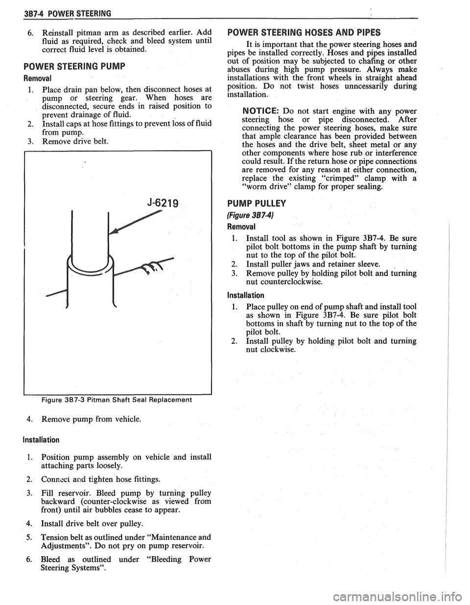
Figure 3B7-3 Pitman Shaft Seal Replacement
4. Remove pump from vehicle.
Installation
1. Position pump assembly on vehicle and install
attaching parts loosely.
2. Gonl7.zct and tighten hose fittings.
3. Fill reservoir. Bleed pump by turning pulley
backward (counter-clockwise as viewed from
front) until air bubbles cease to appear.
4. Install drive belt over pulley.
5. Tension belt as outlined under "Maintenance and
Adjustments". Do not pry on pump reservoir.
6. Bleed as outlined under "Bleeding Power
Steering Systems".
POWER STEERING HOSES AND PIPES
It is important that the power steering hoses and
pipes be installed correctly. Hoses and pipes installed
out of position may be subjected to chafing or other
abuses during high pump pressure. Always make
installations with the front wheels in straight ahead
position. Do not twist hoses unncessarily during
installation.
NOTICE: Do not start engine with any power
steering hose or pipe disconnected. After
connecting the power steering hoses, make sure
that ample clearance has been provided between
the hoses and the drive belt, sheet metal or any
other components where hose rub or interference
could result. If the return hose or pipe connections
are removed for any reason at either connection,
replace the existing "crimped" clamp with a
"worm drive" clamp for proper sealing.
PUMP PULLEY
(Figure 38 7-41
Removal
1. Install tool as shown in Figure 3B7-4. Be sure
pilot bolt bottoms in the pump shaft by turning
nut to the top of the pilot bolt.
2. Install puller jaws and retainer sleeve.
3. Remove pulley by holding pilot bolt and turning
nut counterclockwise.
Installation
1. Place
pulley on end of pump shaft and install tool
as shown in Figure 3B7-4. Be sure pilot bolt
bottoms in shaft by turning nut to the top of the
pilot bolt.
2. Install pulley by holding pilot bolt and turning
nut clockwise.
Page 210 of 1825
POWER STEERING 387-17
POWER STEER ING PUMP
BT-7002-3
BT-7515
POWER STEER ING GEAR
5-2431 801 J-22407
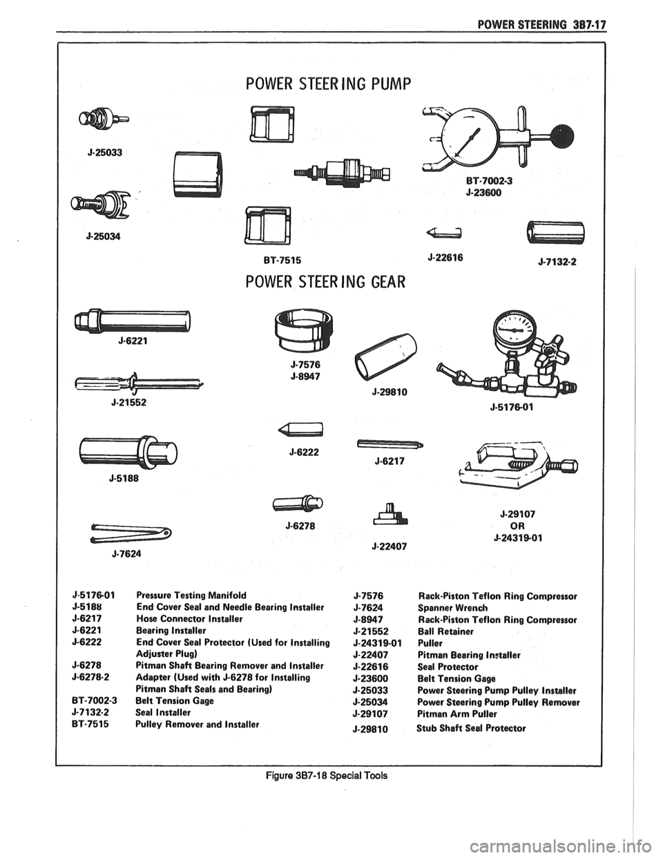
J-517801 Pressure Testing Manifold J-7576 Rack-Piston Teflon Ring Compressor
End Cover Seal and Needle Bearing Installer
J-7624 Spanner Wrench
Hose Connector Installer
J-8947 Rack-Piston Teflon Ring Compreaor
Bearing Installer
5-21552 Ball Retainer
End Cover Seal Protector (Used for Installing
J-24319-01 Puller
Adjuster Plug)
5-22407 Pitman Bearing Installer
Pitman Shaft Bearing Remover and Installer J-22616 Seal Proteaor
5-6278-2 Adapter (Used with 5-6278 for Installing J-23600 Belt Tension Gage
Pitman Shaft Seals and Bearing)
J-25033 Power Steering Pump Pulley Insmller BT-7002-3 Belt Tension Gage 5-25034 Power Steering Pump Pulley Remover
5-7132.2 Seal Installer 5-29107 Pitman Arm Puller
BT-7515 Pulley Remover and lnstaller
J-29810 Stub Shaft Seal Protector
Figure 387-1 8 Special Tools
Page 236 of 1825
TIRES AND WI4EELS 3E-5
require a spacer between the rear wheel and the cast
iron brake drum.
NOTICE: This spacer is not required on
vehicles equipped with four wheel disc brakes or
cast aluminum brake drums.
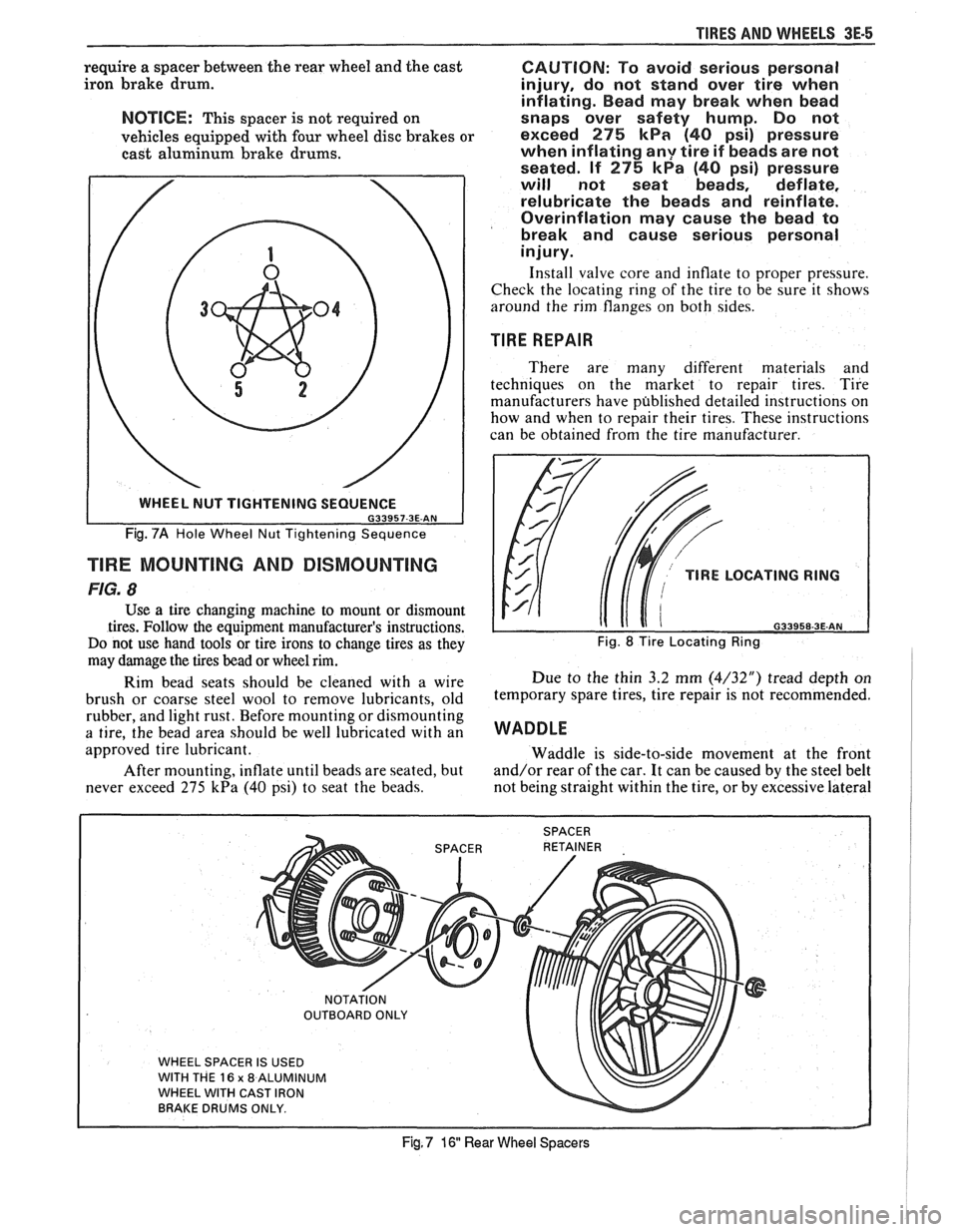
Fig. 7A Hole Wheel Nut Tightening Sequence
TlRE MOUNTING AND DISMOUNTING
FIG. 8
Use a tire changing machine to mount or dismount
tires. Follow the equipment manufacturer's instructions.
Do not use hand tools or tire irons to change tires as they
may damage the tires bead or wheel rim.
Rim bead seats should be cleaned with a wire
brush or coarse steel wool to remove lubricants, old
rubber, and light rust. Before mounting or dismounting
a tire, the bead area should be well lubricated with an
approved tire lubricant.
After mounting, inflate until beads are seated, but
never exceed 275
kPa (40 psi) to seat the beads.
CAUTION: To avoid serious personal
injury, do not stand over tire when
inflating. Bead may break when bead
snaps over safety hump. Do not
exceed
275 kPa (40 psi) pressure
when inflating
any tire if beads are not
seated. If
275 kPa (40 psi) pressure
will not seat beads, deflate,
relubricate the beads and reinflate.
Overinflation may cause the bead to
break and cause serious personal
injury.
Install valve core and inflate to proper pressure.
Check the locating ring of the tire to be sure it shows
around the rim flanges on both sides.
TIRE REPAIR
There are many different materials and
techniques on the market to repair tires. Tire
manufacturers have published detailed instructions on
how and when to repair their tires. These instructions
can be obtained from the tire manufacturer.
TlRE LOCATING RING
naaaca a= AM
Fig. 8 Tire Locating Ring
Due to the thin 3.2 mm (4/32") tread depth on
temporary spare tires, tire repair is not recommended.
WADDLE
Waddle is side-to-side movement at the front
and/or rear of the car. It can be caused by the steel belt
not being straight within the tire, or by excessive lateral
WHEEL SPACER IS USED
WITH THE
16 x 8 ALUMINUM
WHEEL WITH CAST IRON
BRAKE DRUMS ONLY.
Fig, 7 16 Rear Wheel Spacers
Page 346 of 1825
ENGINE GENERAL INFORMATION 6-1
SECTION 6
NE GENERAL NFORMAT
Description ............................................................... 6 TBI ...................................... .. ...... 6E2 ................ Engine Mechanical Multi Port Fuel Injection (MPFI) 6E3 -
............................................... 2.8L V-6 ....................................................... 6A2 Exhaust Systems 6F
5.OL V-8 ......................................................... 6A3 ~~~~~~l ~~f~~~~ti~~ ..................................... 6-2
............................ Engine Cooling ...................................................... 6B Engine Performance Diagnosis 6-3 ............................. Engine Fuel 6C Engine Mechanical Diagnosis
6-3 ........................................................... ................................... Engine Knock Diagnosis 6-4
Engine Electrical ................................................... 6D Compression Test ...................................... ... 6-5
................... Driveability and Emission Controls ...................... 6E Oil Leak Detection .. ..................... 6-5
ALL NEW GENERAL MOTORS VEHICLES ARE CERTIFIED BY THE UNITED STATES
ENVIRONMENTAL PROTECTION AGENCY AS CONFORMING TO THE REQUIREMENTS OF
THE REGULATIONS FOR THE CONTROL OF AIR POLLUTION FROM NEW MOTOR VEHICLES.
THlS CERTIFICATION IS CONTINGENT ON CERTAIN ADJUSTMENTS BEING SET TO
FACTORY STANDARDS. IN MOST CASES, THESE ADJUSTMENT POINTS EITHER HAVE
BEEN PERMANENTLY SEALED AND/OR MADE INACCESSIBLE TO PREVENT
INDISCRIMINATE OR ROUTINE ADJUSTMENT IN THE FIELD. FOR
THlS REASON, THE
FACTORY PROCEDURE FOR TEMPORARILY REMOVING PLUGS, CAPS, ETC., FOR
PURPOSES OF SERVICING THE PRODUCT MUST BE STRICTLY FOLLOWED AND,
WHEREVER PRACTICABLE, RETURNED TO THE ORIGINAL INTENT OF THE DESIGN.
DESCRIPTION OF: SECTION 6
SECTION 6A - ENGINE MECHANICAL used for each carburetor. TBI units are described in
This section general contains information on the Section 6E.
mechanical parts of the engine, such as block,
crankshaft, pistons, valve train, and camshaft, that are
common to most engines. Overhaul procedures,
removal and replacement procedures, and
s~ecifications are also covered. Subsections furnish
detailed information on each specific engine. Service
SECTION 6D - ENG l N E ELECTRICAL
information is also given that relates to that engine's
use in each
Carline. Specific subsections are: Items
covered in this section are battery,
generator, starter, primary and secondary ignition,
6A2
- 2.8L V-6 Engine
engine wire harness, spark plugs and wires, and
6A3
- 5.OL V-8 Engine
ignition switch.
SECTION 6B - ENGINE COOLING
Engine cooling system components such as
radiator, water pump, thermostat, and cooling fan, are
covered in this section. Accessory drive belts are also
covered, along with cooling system capacities.
SECTION 6C - FUEL SYSTEM
This section contains information on all the parts
of the fuel system
except the carburetor, or Throttle
Body Injection unit (TBI) itself. Items covered are fuel
tank, fuel pump, and fuel lines. Specific subsections are
SECTION 6E - DRIVEABILITY AND EMISSIONS
This section covers emission control systems
general information, and diagnostic procedures which
will lead to repairing performance and driveability
related problems for gasoline engine equipped vehicles.
All emission components are covered, as well as all
removal and replacement procedures. Instructions on
use of special tools are also given. Specific sections are:
6E
- Driveability and Emissions
6E2
- Fuel Injection (TBI)
Page 349 of 1825
6-4 ENGINE GENERAL INFORMATION
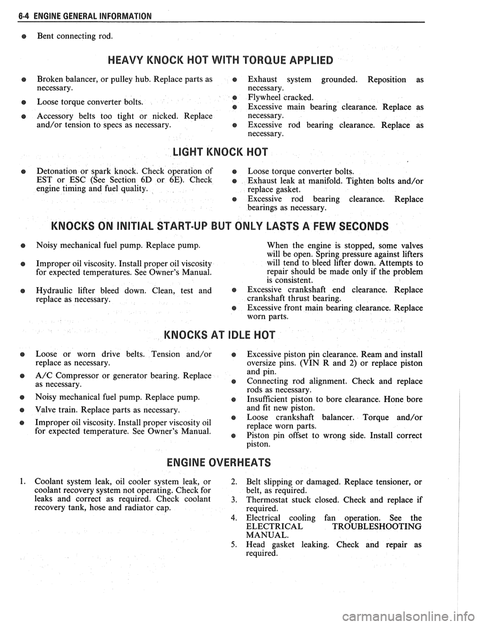
Bent connecting rod.
HEAVY KNOCK H0"FVVI"F TORQUE APPLIED
Broken balancer, or pulley hub. Replace parts as e Exhaust system grounded. Reposition as
necessary. necessary.
Loose torque converter bolts. Flywheel
cracked.
e Excessive main bearing clearance. Replace as
Accessory belts too tight or nicked. Replace
necessary.
and/or tension to specs as necessary.
e Excessive rod bearing clearance. Replace as
necessary.
LIGHT KNOCK HOT
Detonation or spark knock. Check operation of e Loose torque converter bolts.
EST or ESC (See Section
6D or 6E). Check e Exhaust leak at manifold. Tighten bolts and/or
engine timing and fuel quality.
replace gasket.
8 Excessive rod bearing clearance. Replace
bearings as necessary.
KNOCKS ON INITIAL START-UP BUT ONLY LASTS A FEW SECONDS
Noisy mechanical fuel pump. Replace pump.
When the engine is stopped, some valves
will be open. Spring pressure against lifters
Improper oil viscosity. Install proper oil viscosity will
tend to bleed lifter down. Attempts to
for expected temperatures. See Owner's Manual. repair
should be made only if the problem
is consistent.
Hydraulic lifter bleed down. Clean, test and @ Excessive crankshaft end clearance. Replace
replace as necessary. crankshaft
thrust bearing.
@ Excessive front main bearing clearance. Replace
worn parts.
KNOCKS AT IDLE HOT
Loose or worn drive belts. Tension and/or @ Excessive piston pin clearance. Ream and install
replace as necessary. oversize pins. (VIN R and 2) or replace piston
A/C Compressor or generator bearing. Replace and
pin.
as necessary.
e Connecting rod alignment. Check and replace
rods as necessary.
Noisy mechanical fuel pump. Replace pump.
8 Insufficient piston to bore clearance. Hone bore
Valve train. Replace parts as necessary. and
fit new piston.
@ Loose crankshaft balancer. Torque and/or
Improper oil viscosity. Install proper viscosity oil
replace worn parts.
for expected temperature4 See Owner" e Piston pin offset to wrong side. Install correct
ENGINE OVERHEATS
Coolant system leak, oil cooler system leak, or
2. Belt slipping or damaged. Replace tensioner, or
coolant recovery system not operating. Check for belt, as required.
leaks and correct as required. Check coolant
3. Thermostat stuck closed. Check and replace if
recovery tank, hose and radiator cap.
required.
4. Electrical cooling fan operation. See the
ELECTRICAL TROUBLESHOOTING
MANUAL.
5. Head gasket leaking. Check and repair as
required.
Page 363 of 1825
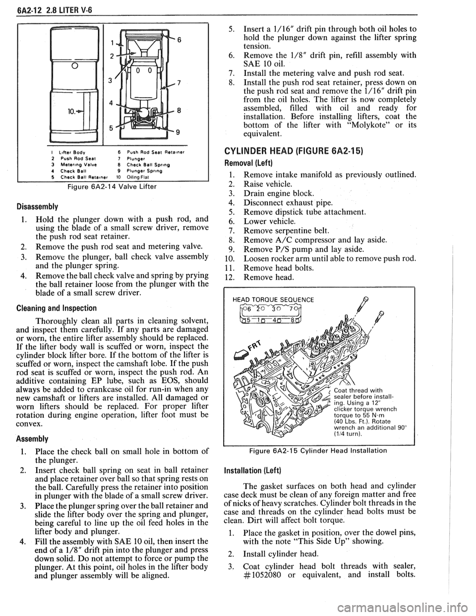
I Liher Body 6 Push Rod Seat Reta~ner 2 Push Rod Seal 7 Plunger 3 Mater~ng Valve 8 Check Ball Spr~ng 4 Check Ball 9 Plunger Spr~ng 5 Check Ball Rete~ner 10 Olllna Flat
Figure 6A2-14 Valve Lifter
Disassembly
1. Hold the plunger down with a push rod, and
using the blade of a small screw driver, remove
the push rod seat retainer.
2. Remove the push rod seat and metering valve.
3. Remove the plunger, ball check valve assembly
and the plunger spring.
4. Remove the ball check valve and spring by prying
the ball retainer loose from the plunger with the
blade of a small screw driver.
Cleaning and Inspection
Thoroughly clean all parts in cleaning solvent,
and inspect them carefully. If any parts are damaged
or worn, the entire lifter assembly should be replaced.
If the lifter body wall is scuffed or worn, inspect the
cylinder block lifter bore. If the bottom of the lifter is
scuffed or worn, inspect the camshaft lobe. If the push
rod seat is scuffed or worn, inspect the push rod. An
additive containing EP lube, such as EOS, should
always be added to crankcase oil for run-in when any
new camshaft or lifters are installed. All damaged or
worn lifters should be replaced. For proper lifter
rotation during engine operation, lifter foot must be
convex.
Assembly
1. Place
the check ball on small hole in bottom of
the plunger.
2. Insert
check ball spring on seat in ball retainer
and place retainer over ball so that spring rests on
the ball. Carefully press the retainer into position
in plunger with the blade of a small screw driver.
3. Place the plunger spring over the ball retainer and
slide the lifter body over the spring and plunger,
being careful to line up the oil feed holes in the
lifter body and plunger.
4. Fill the assembly with SAE 10 oil, then insert the
end of a
1/8" drift pin into the plunger and press
down solid. Do not attempt to force or pump the
plunger. At this point, oil holes in the lifter body
and plunger assembly will be aligned.
5. Insert a 1/16" drift pin through both oil holes to
hold the plunger down against the lifter spring
tension.
6. Remove
the
1/8" drift pin, refill assembly with
SAE 10 oil.
7. Install the metering valve and push rod seat.
8. Install the push rod seat retainer, press down on
the push rod seat and remove the 1/16" drift pin
from the oil holes. The lifter is now completely
assembled, filled with oil and ready for
installation. Before installing lifters, coat the
bottom of the lifter with "Molykote" or its
equivalent.
CYLINDER HEAD (FIGURE 6A2-15)
Removal (Left)
Remove intake manifold as previously outlined.
Raise vehicle.
Drain engine block.
Disconnect exhaust pipe.
Remove dipstick tube attachment.
Lower vehicle.
Remove serpentine belt.
Remove A/C compressor and lay aside.
Remove
P/S pump and lay aside.
Loosen rocker arm until able to remove push rod.
Remove head bolts.
Remove head.
HEAD TORQUE SEQUENCE
/7 , 2 ing. Using a 12"
Figure 6A2-1'5 Cylinder Head Installation
Installation (Left)
The gasket surfaces on both head and cylinder
case deck must be clean of any foreign matter and free
of nicks of heavy scratches. Cylinder bolt threads in the
case and threads on the cylinder head bolts must be
clean. Dirt will affect bolt torque.
1. Place the gasket in position, over the dowel pins,
with the note "This Side Up" showing.
2. Install cylinder head.
3. Coat cylinder head bolt threads with sealer,
#1052080 or equivalent, and install bolts.
Page 364 of 1825
2.8 LITER V.6 6A2.13
Torque bolts as shown in Figure 6A2-15.
4. Install
push rods and loosely retain with rocker
arms. Make sure lower ends of
pushrods are in
lifter seats.
5. Install intake manifold.
6. Raise vehicle.
7. Install dipstick tube bracket.
8. Connect exhaust pipe
to exhaust manifold flange.
9. Lower vehicle.
10. Adjust
valve lash as previously outlined.
11. Continue
following intake manifold installation
for build up.
Removal (Right)
Remove intake manifold as previously outlined.
Raise vehicle.
Disconnect exhaust pipe.
Drain engine block.
Lower vehicle.
Loosen rocker arms until able to remove push
rod.
Remove serpentine belt.
Remove tensioner.
Remove A.I.R. bracket.
Remove generator bracket.
Remove head bolts.
Remove head.
Installation (Right)
The gasket surfaces on both the head and cylinder
case
deck must be clean of any foreign matter and free
of nicks of heavy scratches. Cylinder bolt threads in the
case and threads on the cylinder head bolts must be
clean. Dirt will affect bolt torque.
1. Place the gasket in position, over the dowel pins,
with the note "This Side Up" showing.
2. Install cylinder head.
3. Coat cylinder head bolt threads with sealer,
#lo52080 or equivalent, and install bolts.
Torque bolts as shown in (Figure
6A2-15).
Install push rods and loosely retain with rocker
arms. Make sure lower ends of push rods are in
lifter seats.
Install intake manifold.
Raise vehicle.
Install exhaust pipe to exhaust manifold flange.
Lower vehicle.
Adjust valve lash as previously outlined.
Install AIR bracket.
Install tensioner.
Install generator bracket.
Continue following intake manifold installation
for build up.
Disassembly
1. With cylinder head removed, remove rocker arm
nuts, balls and rocker arms (if not previously
done).
2. Using tool J-8062, compress the valve springs and
remove valve keys. Release the compressor tool and
remove spring caps, oil shedders, springs and
damper assemblies, then remove oil seals.
3. Remove valves from cylinder head and place
them in a rack so they can be installed in their
original positions.
Cleaning and Inspection
Clean all carbon from combustion chambers and
valve ports using 'tool
5-8089.
Thoroughly clean valve guides using 5-8 10 1.
Clean all carbon and sludge from push rods,
rocker arms and push rod guides.
Clean valve stems and heads on a buffing wheel.
Clean carbon deposits from head gasket mating
surface.
Inspect cylinder head for cracks in the exhaust
ports, combustion chambers, or external cracks
to the water jacket.
Inspect the valves for burned heads, cracked faces
or damaged stems.
NOTICE: Excessive valve stem to bore clearance
will cause high oil consumption and may cause
valve breakage. Insufficient clearance will result in
noise and sticky functioning of the valve and
disturb engine smoothness.
8. Measure valve stem clearance as follows:
a. Clamp
a dial indicator on one side of the
cylinder head. Locate the indicator so that
movement of the valve stem from side to
side (crosswise to the head) will cause direct
movement of the indicator stem. The
indicator stem must contact the side of the
valve stem just above the guide.
b. Drop
the valve head
1.5mm off the valve
seat.
c. Move
the stem of the valve from side to side,
using light pressure, to obtain a clearance
reading. If clearance exceeds specifications,
it will be necessary to ream valve guides for
oversize valves. Service valves are available
in std., 089,
.394 and .775mm O.S. sizes.
9. Check
valve spring tension with tool J-8056,
spring tester. Springs should be compressed to the
specified height and checked against the
specifications chart. Springs should be replaced if
not within 44
N (10 Ibs.) of the specified load
(without dampers).
10. Inspect
rocker arm studs for wear or damage.
ROCKER ARM STUDS
Cylinder heads use threaded rocker arm studs.
Rocker arm studs that have damaged threads should
be replaced with new studs. If, for some reason, the
threads in the head
are damaged or stripped, the head
can be retapped, and a helical type insert added. If such
an insert is not available, the head should be replaced.
VALVE GUIDES
Valves with oversize stems are available in .089,
,394 and ,775mm over sizes. To ream the valve guide
Page 365 of 1825
BA2-14 2.8 LITER V-6
bores for oversize valves use tool 5-5330-1, 2 or 3,
respectively.
VALVE SEATS
Reconditioning the valve seats is very important,
because the seating of the valves must be perfect for the
engine to deliver the power and performance designed
into it.
Another important factor is the cooling of the
valve heads. Good contact between each valve and its
seat in the head is imperative to insure that the heat in
the valve head will be properly carried away.
Several different types of equipment are available
for reseating valve seats. The recommendations of the
manufacturer of the equipment being used should be
carefully followed to attain proper results.
VALVES
Valves that are pitted can be refaced, to the
proper angle, insuring correct relation between the
head and stem, on a valve
refacing machine. Valve
stems which show excessive wear, or valves that are
warped excessively should be replaced. When a valve
head which is warped excessively is
refaced, a knife
edge will be ground on part or all of the valve head due
to the amount of metal that must be removed to
completely
reface the valve. Knife edges lead to
breakage, burning or preignition due to heat localizing
on this knife edge. If the edge of the valve head is less
than
.8mm thick after grinding, replace the valve.
Several different types of equipment are available
for
refacing valves. The recommendations of the
manufacturer of the equipment being used should be
carefully followed to attain the proper results.
Assembly
Insert a valve in the proper port.
Install a valve stem seal over the valve stem and
valve guide base inlet only.
Drop an oil shedder and valve rotator over the
exhaust and a valve spring cap over the valve
spring.
Using tool
5-8062 compress the valve spring.
Install the square cut
"0" ring around the valve
stem in the lower groove, making sure it is not
twisted.
Insert valve, stem key locks and release tool.
Install the valve locks and release the compressor
tool making sure that the locks seat properly in
the upper groove of the valve stem. Grease may
be used to hold the locks in place while releasing
the compressor tool.
Install the remaining valves.
Check each valve stem oil seal by placing valve
stem leak detector, tool J-23994, over the end of
the valve stem and against the cap. Operate the
vacuum pump and make sure no air leaks pass the
seal.
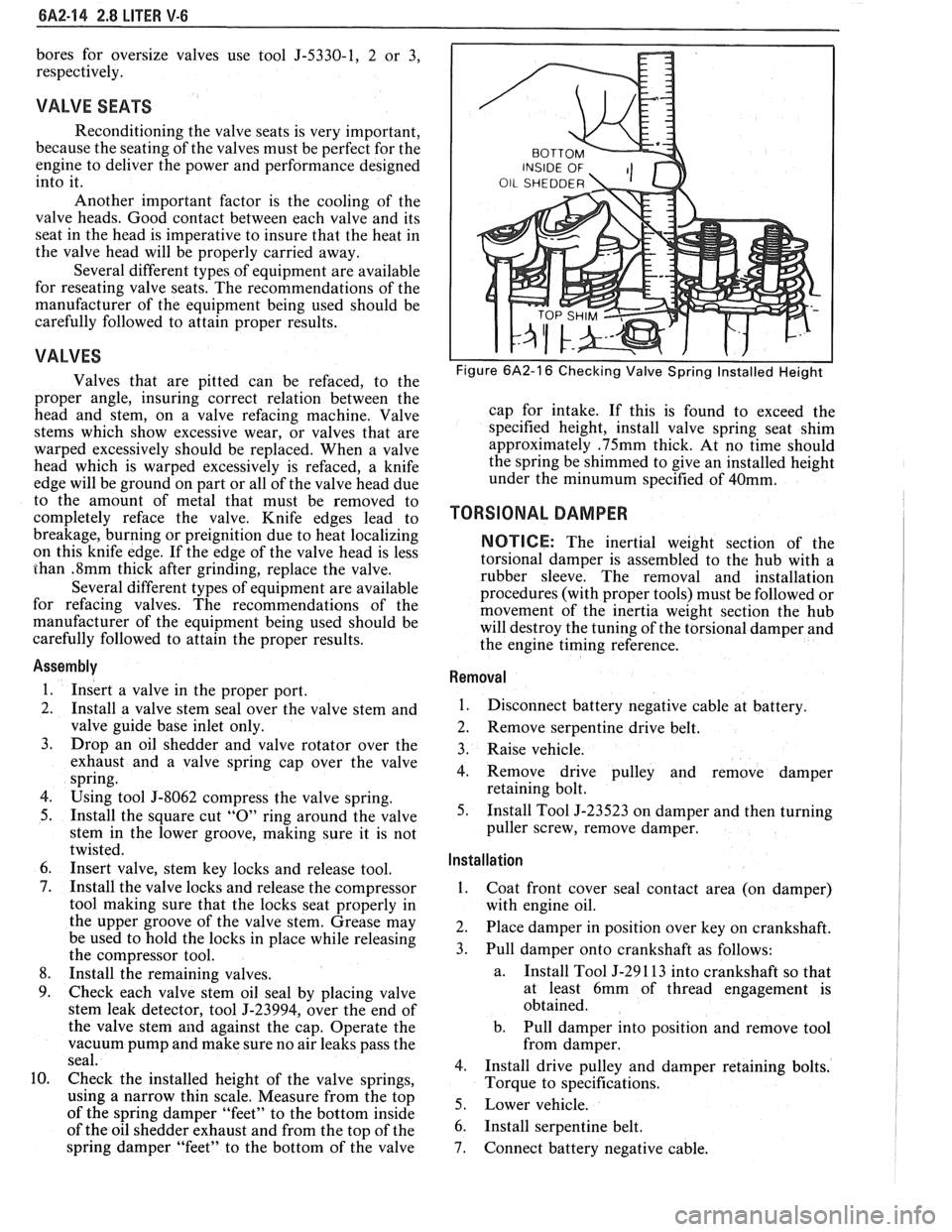
Check the installed height of the valve springs,
using
a narrow thin scale. Measure from the top
of the spring damper "feet" to the bottom inside
of the oil shedder exhaust and from the top of the
spring damper "feet" to the bottom of the valve
Figure 6A2-16 Checking Valve Spring Installed Height
cap for intake. If this is found to exceed the
specified height, install valve spring seat shim
approximately
.75mm thick. At no time should
the spring be shimmed to give an installed height
under the
minumum specified of 40mm.
TORSIONAL DAMPER
NOTICE: The inertial weight section of the
torsional damper is assembled to the hub with a
rubber sleeve. The removal and installation
procedures (with proper tools) must be followed or
movement of the inertia weight section the hub
will destroy the tuning of the torsional damper and
the engine timing reference.
Removal
1.
Disconnect battery negative cable at battery.
2. Remove serpentine drive belt.
3. Raise vehicle.
4. Remove drive pulley and remove damper
retaining bolt.
5. Install Tool J-23523 on damper and then turning
puller screw, remove damper.
Installation ,
1.
Coat front cover seal contact area (on damper)
with engine oil.
2. Place damper in position over key on crankshaft.
3. Pull damper onto crankshaft as follows:
a. Install
Tool J-29 1 13 into crankshaft so that
at least 6mm of thread engagement is
obtained.
b. Pull damper into position and remove tool
from damper.
4. Install drive pulley and damper retaining bolts.
Torque to specifications.
5. Lower vehicle.
6. Install serpentine belt.
7. Connect battery negative cable.