1988 PONTIAC FIERO belt
[x] Cancel search: beltPage 551 of 1825
6EZ-B-4 5.OL (VIN E) DRIVEABILITY AND EMISSIONS
DEWNATION 1 SPARK KNOCK
Definition: A mild to severe ping, usually worse under acceleration. The
engine makes sharp metallic knocks that change with throttle opening.
@ CHECK for obvious overheatingproblems. - For proper transmission shift points. See Section
- Low coolant. "7".
- Loose water pump belt. - TCC operation. See CHART C-8.
- Restricted air flow to radiator, or restricted - For incorrect basic engine parts such as cam,
water flow thru radiator. heads,
pistons, etc.
- Faulty or incorrect thermostat. - Excessive oil entering combustion chamber.
- Coolant sensor, which has shifted in value. @ Remove carbon with top engine cleaner. Follow
- Correct coolant solution - should be a 50150 instructions on can.
mix of GM
#lo52753 anti-freeze coolant (or @ If there is spray from only one injector, then there
equiv.) and water. is
a malfunction in the injector assembly, or in the
@ CHECK: signal to the injector assembly. The malfunction
- For poor fuel quality, proper octane rating. can be isolated by switching the injector
- For correct PROM. connectors. If the problem remains with the
- Spark plugs for correct heat range.
original injector, after switching the connector,
- ESC system opeation. See CHART C-5.
then the injector is defective. Replace the injector.
- Ignition timing. See Vehicle Emission Control
If the problem moves with the injector connector,
Information label. then the
problem is an improper signal in the
- Fuel system for low pressure. See CHART A-7.
injector circuits. See CHART A-3.
- Check EGR svstem. - CHART C-7.
HESITATION, SAG, STUMBLE
Definition: Momentary lack of response as the accelerator is pushed down.
Can occur at all car speeds.
C'sually most severe when first trying to make the car
move, as from a stop sign.
May cause the engine to stall if severe enough.
@ Perform careful visual (physical) check, as Information" label.
described at start of Section
"B". - Generator output voltage. Repair if less than 9 or
@ CHECK: more than 16 volts.
- Fuel pressure. See CHART A-7. - For open ignition system ground, CKT 453.
- Water contaminated fuel. - Canister purge system for proper operation. See
- TPS for binding or sticking.
Section "C3".
- Ignition timing. See "Emission Control - EGR valve operation, CHART C-7.
CU"F OUT, MISSES
Definition: Steady pulsation or jerking that follows engine
speed, usually more pronounced as engine load increases. The
exhaust has a steady spitting sound at idle or low speed.
@ Perform careful visual (physical) check, us
described at start of Section
"B".
@ If ignition system is suspected of causing a miss
at idle or cutting, out under load:
@ Check for missing cylinder by:
1. Disconnect IAC motor. Start engine.
Remove one spark plug wire at a time, using
insulated pliers.
2. If there is an rpm drop on all cylinders, (equal
to within 50
rpm), go to "Rough, Unstable, Or
Incorrect Idle, Or Stalling" symptom.
Reconnect
IAC motor.
3. If there is no rpm drop on one or more
cylinders, or excessive variation in drop, check
for spark, on the suspected
cylinder(s) with J
26792 (ST-1251 spark tester or equivalent. If no
spark, see Section
"6D" for "Intermittent Operation
or Miss". If there is spark, remove spark plug(s) in
these cylinders and check for:
- Cracks
- Wear
- Improper gap
- Burned electrodes
- Heavy deposits
- Perform compression check on
questionable cylinder.
@ Check wire resistance (shoulcl not exceed 30,000
ohms), also, check rotor and distributor cap.
Page 612 of 1825
DRIVEABILITY AND EMISSIONS 5.OL (VIN E) 6EZ-C6-1
SECTION C6
AIR INJECTION REACTION (A.I.R.) SYSTEM
CONTENTS
GENERAL DESCRIPTION ............... C6-1
PURPOSE ......................... C6-1
OPERATION ...................... C6-1
AIR CONTROL PEDES VALVE .......... C6-1
RESULTS OF INCORRECT OPERATION .... C6-2
DIAGNOSIS
........................ C6-2
OPERATIONAL CHECKS .............. C6-2
AirPump ...................... C6-2
Hoses and Pipes ................. C6-3
GENERAL DESCRIPTION
PURPOSE
The A.I.R. system helps reduce hydrocarbon (HC),
carbon monoxide (CO), and oxides of nitrogen (NO,)
exhaust emissions. It also heats up the catalytic
converter quickly on engine start-up so conversion of
exhaust gases can occur sooner.
A Dual bed converter is used. It consists of a three
way catalyst (which controls all three emissions) in
series with
a two way catalyst (which controls only HC
and
CO) both are in one housing. A pipe between the
two converters allows air to be injected into the second
(two way) converter to increase its efficiency to further
control
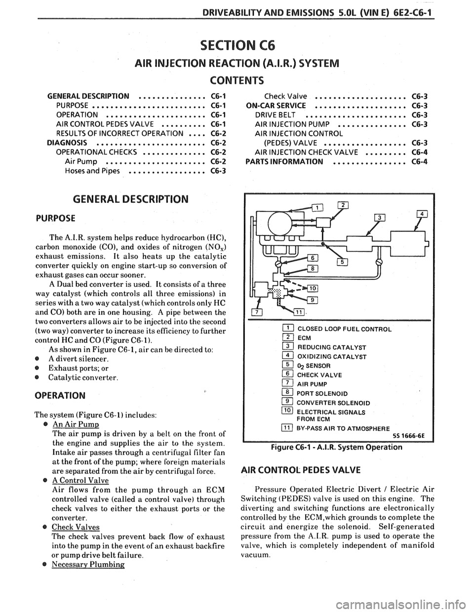
HC and CO (Figure C6-1).
As shown in Figure C6-1, air can be directed to:
@ A divert silencer.
@ Exhaust ports; or
@ Catalytic converter.
OPERATION
The system (Figure C6-1) includes:
@ An Air Pump
The air pump is driven by a belt on the front of
the engine and supplies the air to the system.
Intake air passes through a centrifugal filter fan
at the front of the pump; where foreign materials
are separated from the air
by centrifugal force.
@ A Control Valve
Air flows from the pump through an ECM
controlled valve (called a control valve) through
check valves to either the exhaust ports or the
converter.
@ Check Valves
The check valves prevent back flow of exhaust
into the pump in the event of an exhaust backfire
or pump drive belt failure.
@ Necessary Plumbing
Check Valve .................... C6-3
ON-CAR SERVICE
.................... C6-3
DRIVEBELT ...................... C6-3
AIR INJECTION PUMP ............... C6-3
AIR INJECTION CONTROL
(PEDES) VALVE
.................. C6-3
AIR INJECTION CHECK VALVE ......... C6-4
PARTS INFORMATION
................ C6-4
CLOSED LOOP FUEL CONTROL
ECM
1 REDUCING CATALYST - 1 OXlDlZlNG CATALYST
1 5 SENSOR
CHECK VALVE
1 AIR PUMP
1 PORT SOLENOID
CONVERTER SOLENOID
/ ELECTRICAL SIGNALS
FROM ECM
BY-PASS AIR TO ATMOSPHERE
Figure C6-1 - A.I.R. System Operation
AIR CONTROL PEDES VALVE
Pressure Operated Electric Divert / Electric Air
Switching (PEDES) valve is used on this engine. The
diverting and switching functions are electronically
controlled by the
ECM,which grounds to complete the
circuit and energize the solenoid. Self-generated
pressure from the A.I.R. pump is used to operate the
valve, which is completely independent of manifold
vacuum.
Page 613 of 1825
6EZ-C6-2 5.OL (VIN E) DRIVEABILITY AND EMISSIONS
Air enters the body of the valve from the pump.
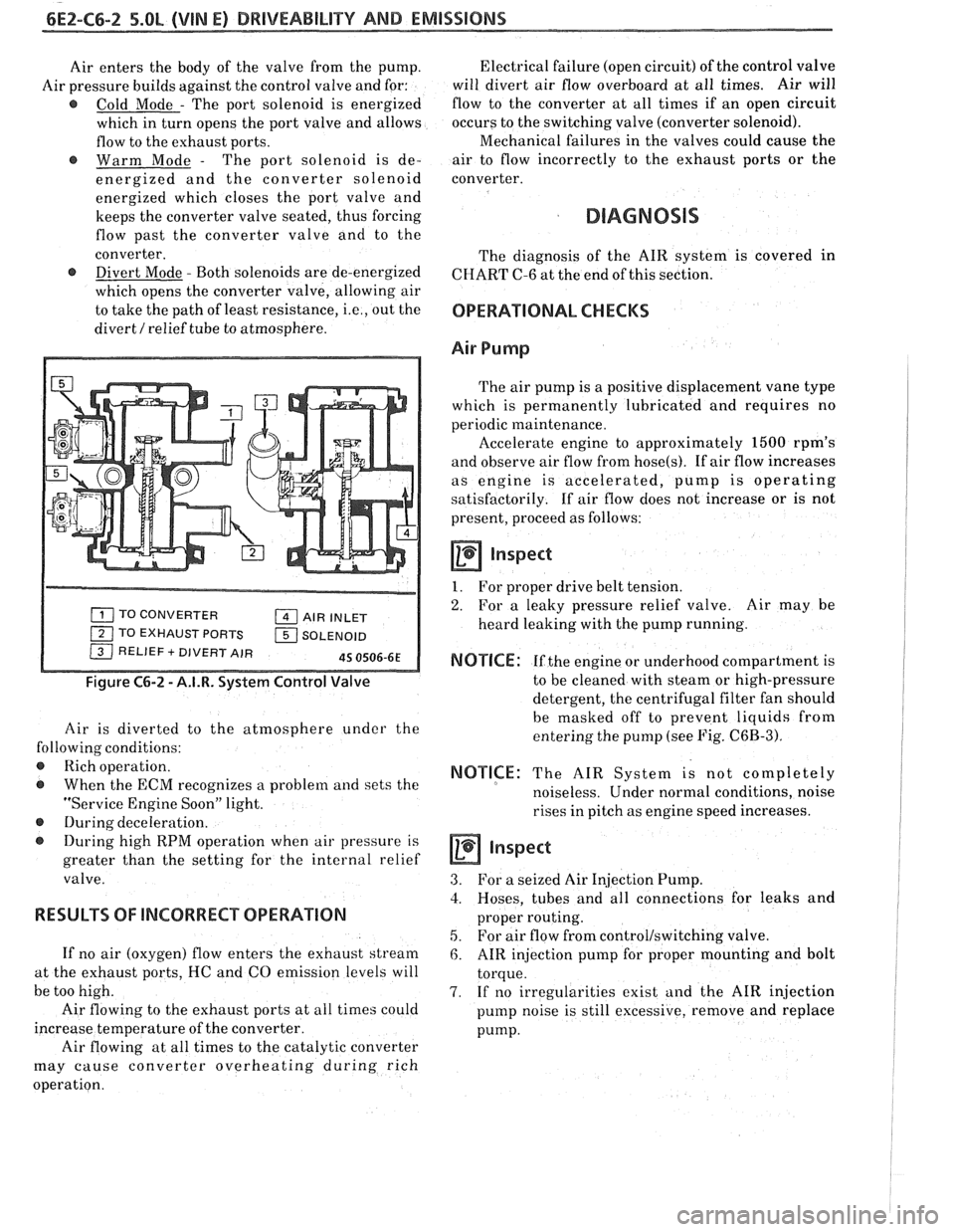
Air pressure builds against the control valve and for:
@ Cold Mode - The port solenoid is energized
which in turn opens the port valve and allows
flow to the exhaust ports.
@ Warm Mode - The port solenoid is de-
energized and the converter solenoid
energized which closes the port valve and
keeps the converter valve seated, thus forcing
flow past the converter valve and to the
converter.
@ Divert Mode - Both solenoids are de-energized
which opens the converter valve, allowing air
to take the path of least resistance,
i.e., out the
divert
/ relief tube to atmosphere.
TO CONVERTER AIR INLET
1 TO EXHAUST PORTS 1 SOLENOID / RELIEF + DIVERT AIR 45 0506-6E
Figure C6-2 - A.I.R. System Control Valve
Air is diverted to the atmosphere under the
following conditions:
@ Rich operation.
@ When the ECM recognizes a problem and sets the
"Service Engine Soon" light.
@ During deceleration.
During high RPM operation when air pressure is
greater than the setting for the internal relief
valve.
RESULTS OF lNCORRECP OPERATION
If no air (oxygen) flow enters the exhaust stream
at the exhaust ports, HC and CO emission levels will
be too high.
Air flowing to the exhaust ports at all times could
increase temperature of the converter.
Air flowing at all times to the catalytic converter
may cause converter overheating during rich
operation. Electrical failure
(open circuit) of the control valve
will divert air flow overboard at all times. Air will
flow to the converter at all times if an open circuit
occurs to the switching valve (converter solenoid).
Mechanical failures in the valves could cause the
air to flow incorrectly to the exhaust ports or the
converter.
DIAGNOSIS
The diagnosis of the AIR system is covered in
CHART C-6 at the end of this section.
OPERATIONAL CHECKS
Air Pump
The air pump is a positive displacement vane type
which is permanently lubricated and requires no
periodic maintenance.
Accelerate engine to approximately
1500 rpm's
and observe air flow from
hose(s). If air flow increases
as engine is accelerated, pump is operating
satisfactorily. If air flow does not increase or is not
present, proceed as follows:
a Inspect
1. For proper drive belt tension.
2. For a leaky pressure relief valve. Air may be
heard leaking with the pump running.
NOTICE: If the engine or underhood compartment is
to be cleaned with steam or high-pressure
detergent, the centrifugal filter fan should
be masked off to prevent liquids from
entering the pump (see Fig.
C6B-3).
NOTICE: The AIR System is not completely
noiseless. Under normal conditions, noise
rises in pitch as engine speed increases.
inspect
3. For a seized Air Injection Pump.
3. Hoses, tubes and all connections for leaks and
proper routing.
5. For air flow from control/switching valve.
6. AIR injection pump for proper mounting and bolt
torque.
7. If no irregularities exist and the AIR injection
pump noise is still excessive, remove and replace
pump.
Page 614 of 1825

DRIVEABILITY AND EMISSIONS 5.OL (VIN E) 6EZ-C6-3
CAUTION: Do Not Oil A.I.R. Pump
Hoses and Pipes
inspect
1. Hose or pipe for deterioration or holes.
2. All hoses or pipe connections, and clamp tightness.
3. Hose or pipe routing. Interference may cause
wear.
4. If a leak is suspected on the pressure side of the
system or if a hose or pipe has been disconnected
on the pressure side, the connections should be
checked for leaks with a soapy water solution.
With the pump running, bubbles will form if a
leak exists.
Check Valve
a inspect
1. A check valve should be inspected whenever the
hose is disconnected form a check valve or
whenever check valve failure is suspected.
(A
pump that had become inoperative and had shown
indications of having exhaust gases in the pump
would indicate check valve failure).
2. Blow through the check valve (toward the cylinder
head) then attempt to suck back through the check
valve Flow should only be in one
direction(toward the exhaust manifold). Replace
valve which does not operate properly.
ON-CAR SERVICE
DRIVE BELT
Remove or Disconnect
1. Inspect drive belt for wear, cracks or deterioration
and replace if required. When installing new belt,
it must be seated and fully secured in grooves of
all belt driven components.
AIR INJECTION PUMP
Remove or Disconnect
1. Hold pump pulley from turning by compressing
drive belt, then loosen pump pulley bolts.
2. Drive belt and pulley.
3. Hoses, vacuum, and electrical connections from
Air Injection Control valve.
4. Air pump mounting bolts, and pump assembly
(See Figure
C6-3).
Install or Connect
1. Air pump assembly, and tighten mounting bolts.
2. Spacer and pump pulley against centrifugal filter
fan.
3. Pump pulley bolts and tighten equally to 13 N m
(10 lb, ft).
4. Check
air injection system for proper operation
(see Chart C-6).
Figure C6-3 - Air Pump Service
AIR INJECTION CONTROL (PEDES) VALVE
Remove or Disconnect
1. Battery ground cable.
2. Adapter bolts (See Figure C6-4).
3. Air outlet hoses from valve.
4. Splash guard / cover
5. Electrical connectors and vacuum hoses from
valve.
6. Control valve.
Install or Connect
1. Control valve.
2. Electrical connectors.
3. Splash guard /cover
4. Air hoses to valve.
5. Battery ground cable.
6. Check
system operation (see
CHART C-6).
Page 648 of 1825
DRlVEABlLlTVAND EMISSIONS 2.8L (VIN S). 5.OL (VIN F) & 5.7L (VIN 8) 6E3-3
.................... FUEL PUMP ELECTRICAL CIRCUIT ....... C2-4 CANISTER HOSES C3-3
................ DIAGNOSIS ......................... C2-5 PARTS INFORMATION C3-3
FUEL CONTROL SYSTEM .............. C2-5 Canister Purge Valve Check
......................... IDLE AIR CONTROL VALVE ............ C2-5 Chart C-3 C3-4
ON-CAR SERVICE
..................... C2-5
.... PORT FUEL INJECTION COMPONENTS C2-5
FUEL PRESSURE RELIEF PROCEDURE ..... C2-5
Plenum ........................ C2-5
Fuel Rail & Pressure Regulator Assembly . C2-5
FUEL RAIL SERVICE ................. C2-6
UNIT SERVICE PROCEDURES ........... C2-6
COLD START TUBE & VALVE ASSEMBLY ... C2-7
FUEL PRESSURE CONNECTION ASSEMBLY . C2-7
FUEL BLOCK AND SEAL ............... C2-9
FUEL INJECTORS .................... C2-9
Port Injectors wl Injector Retaining Clips C2-9
Fuel Pressure Regulator ............ C2-10
PORT INJECTORS ................... C2-10
PRESSURE REGULATOR ............... C2-10
COLD START FUEL INJECTION SWITCH ...
THROTTLE BODY ...................
THROTTLE BODY SERVICE IDENTIFICATION
MINIMUM IDLE SPEED ADJUSTMENT
....
UNIT REPAIR PROCEDURES ............
IDLE AIR CONTROL VALVE
ASSEMBLY
& GASKET ................
IDLE AIR I VACUUM SIGNAL
HOUSING ASSEMBLY
................
COOLANT CAVITY COVER & O-RING .....
IDLE AIR CONTROL I COOLANT
COVER ASSEMBLY
..................
FUEL PUMP RELAY ..................
OIL PRESSURE SWITCH ...............
PARTS INFORMATION .................
Injector Balance Test
Chart C-2A
........................
Idle Air Control
Chart C-2C
........................
SECTION C3 . 2.8L (WIN S)
EVAPORATIVE EMISSION CONTROL (EECS) SYSTEM
GENERAL
DESCRIPTION ............... C3-1
PURPOSE ........................ C3-1
VAPOR CANISTER ................... C3-1
EVAPORATIVE EMISSION SYSTEM ...... C3-1
TANK PRESSURE CONTROL VALVE ...... C3-2
.... RESULTS OF INCORRECT OPERATION C3-2
DIAGNOSIS
........................ C3-2
VISUAL CHECK OF CANISTER .......... C3-2
FUNCTIONAL TEST
Vapor Canister Purge Valve
........ C3-2
..... Fuel Tank Pressure Control Valve C3-2
ON-CAR SERVICE
................. C3-3
FUEL VAPOR CANISTER WR ............ C3-3
FUEL VAPOR CANISTER SOLENOID WR .... C3-3
SECTION C4 . 2.8L (VIN S)
IGNITION
SQSTEMIEST
................ GENERAL DESCRIPTION C4-1
......................... PURPOSE C4-1
OPERATION ....................... C4-1
RESULTS OF INCORRECT OPERATION .... C4-2
DIAGNOSIS
......................... C4-2
CODE 12 .......................... C4-2
ON-CAR SERVICE ..................... C4-2
SETTING TIMING .................... C4-2
HOW CODE 42 IS DETERMINED ......... C4-2
PARTS INFORMATION ................. C4-2
Ignition System Check
Chart C-4A
........................ C4-4
SECTION C6 . 2.8L (VIN S)
AIR INJECTION REACTION (A.I.R.) SYSTEM
MANUAL TRANSMISSION ONLY
............... GENERAL DESCRIPTION C6-1
........................ PURPOSE C6-1
............. A.I.R. PUMP OPERATION C6-I
..................... AIR CONTROL C6-1
.......... Electric Air Control Valve C6-1
............... Deceleration Valve C6-2
... RESULTS OF INCORRECT OPERATION C6-2
........................ DIAGNOSIS C6-2
............. OPERATIONAL CHECKS C6-2
.................... A.I.R. Pump C6-2
................. Hoses and Pipes C6-2
............... Deceleration Valve C6-3
.................... Check Valve C6-3
.................... ON-CAR SERVICE C6-3
...................... DRIVEBELT C6-3
....................... A.I.R. PUMP C6-3
............... AIR CONTROL VALVE C6-3
.................... CHECKVALVE C6-4
DECELERATION VALVE .............. C6-4
................ PARTS INFORMATION C6-5
Electric Control (Divert)
(Manual Transmission)
........................ Chart C-6 C6-6
SECTION C7
. 2.8L (VIN S)
EXHAUST GAS RECIRCULATION (EGR) SYSTEM
GENERAL DESCRIPTION
................ C7-1
......................... PURPOSE C7-1
....................... OPERATION C7-I
ELECTRONIC VACUUM REGULATOR
........................... VALVE C7-1
................... PORT EGR VALVE C7-2
........... EGR VALVE IDENTIFICATION C7-2
... RESULTS OF INCORRECT OPERATION C7-2
......................... DIAGNOSIS C7-3
Page 651 of 1825
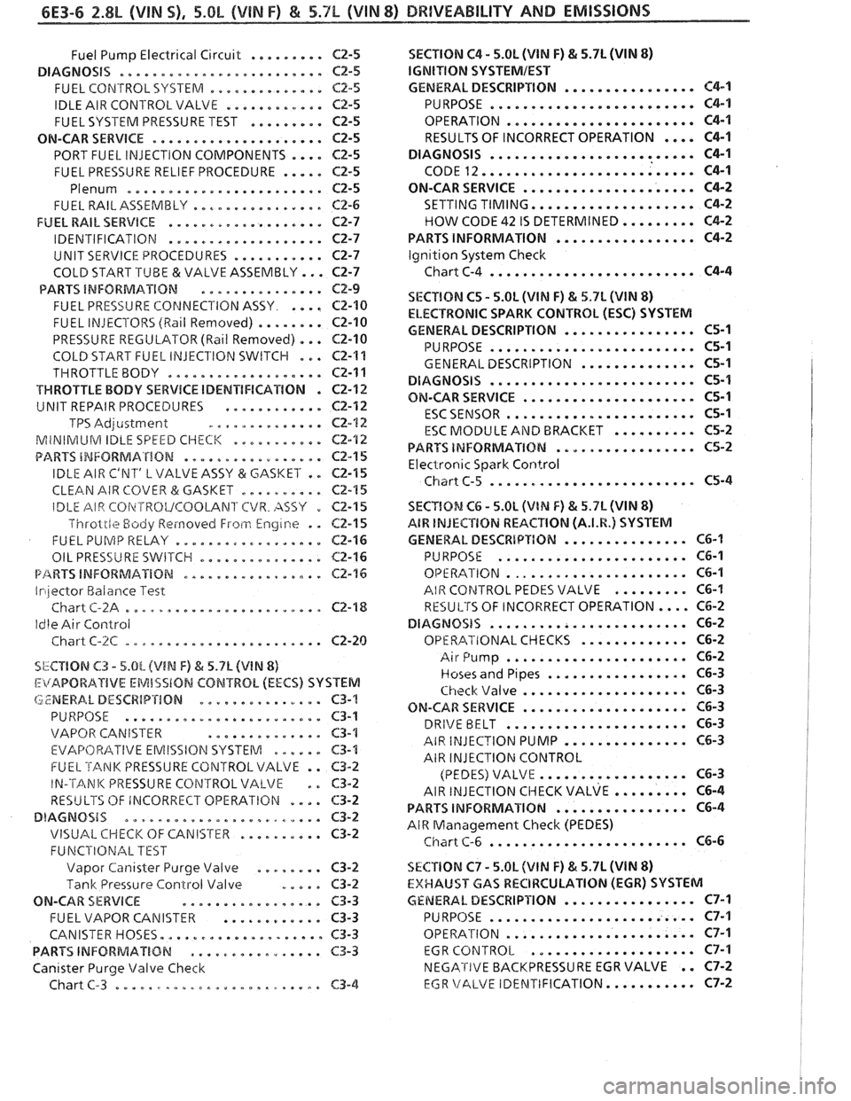
6E3-6 2.8L (VIN S). 5.OL (&BIN F) & 5.7L (WIN 8) BRllVEABlhlPY AND EMISSIONS
......... Fuel Pump Electrical Circuit C2-5
DIAGNOSiS ......................... CZ-5
.............. FUEL CONTROL SYSTERA C2.5
............ IDLE AIR CONTROLVALVE CZ-5
......... FUEL SYSTEM PRESSURE TEST C2-5
ON-CAR SERVICE ..................... C2-5
PORT FUEL INJECTION COMPONENTS .... Cf-5
FUEL PRESSURE RELIEF PROCEDURE ..... C2-5
Plenum ......................... C2-5
................ FUEL RAILASSEMBLY CP-6
FUEL RAIL SERVICE ................... C2-7
................... IDENTIFICATION C2-7
........... UNIT SERVICE PROCEDURES C2-7
COLD START .TUBE & VALVE ASSEMBLY ... ~2-7
PARTS INFORMATION ............... CZ-9
.... FUEL PRE5Si.J RE COPdNECl'ION ASSY C2-10
FUEL INJECTORS (Rail Removed) ........ C2-10
PRESSURE REGULATOR (Ball Removed) ... C2-10
COLD START FUEL INJEClION SWITCH ... C2-1%
THROTTLE BODY ................... CZ-11
VWROTTLE BODY SERVICE IDENTIFICATION . C2-12
............ UNIT REPAIR PROCEDURES Cf-112
TPS Adjcistment .............. C2-12
MiNIRilUM IDLE SPEED CHECK ........... CE-'I2
................. PARTS INFORMATION C2-15
IDLE AIR C'NT' L VALVE ASSY (3r: GASKET . . C2-15
CLEAN AIR COVER & GASKET .......... C2-15
SECTION C4 . 5.0h (VIN F) & 5.7L (VIN 8)
lGNITlON SYSTEMIEST
................ GENERAL DESCRIPTION C4-1
......................... PURPOSE C4-1
OPERATION ....................... C4-1
RESULTS OF INCORRECT OPERATION .... C4-1
......................... DIAGNOSIS C4-1
CODE 12 .......................... C4-1
ON-CAR SERVICE ..................... C4-2
SETTING TIMING .................... C4-2
HOW CODE 42 IS DETERMINED ......... C4-2
................. PARTS INFORMATION C4-2
lgn~tion System Check
Chart C-4
......................... C4-4
SECTION C5 . 5.0L (VIM F) & 5.7L JVIN 8)
ELECTRONIC SPARK CONTROL (ESC) SYSTEM
................ GENERAL DESCRIPTION C5-1
......................... PURPOSE C5-1
.............. GENERAL DESCRIPTION C5-1
......................... DlAGNOSiS C5-1
..................... ON-CAR SERVICE C5-1
....................... ESCSENSOR 65-1
.......... E4C MODULE AiYD BRACKET 165-2
................. PARTS INFORMATXBM C5-2
Electronic Spark Control
Chiirt C-5 ......................... C5-4
IDLE AIR CBi\~TROVCOOLANl'CVR . AS57 0
Throlrle Body Reinovecl Froti.1 Engine . .
FUEL PUlVlP RELAY ..................
................ OIL PRESSURE 5WETCI-I
P/%RVS INFORMATION .................
Irilector Halarlce Test
Chart
C-2A ........................
Idle Air Control
Chart
C-%C ........................
C2-I 5 SECYlOM Ct; . 5.0L (VlN F) & 5.7L (VIN 8)
62-1 5 A8W INJECTION REACTION (A.I.R.) SYSTEM
C2-16 GENERAL DESCRbPTION ............... CG-I
C2-16 PURPOSE ....................... C6-1
C2-76 OPE RATION ...................... C6-1
AIR COPJTROL PEDES VALVE ......... C6-I
C2-'18 RESULTS OF INCORRECT OPERATION .... C6-2
DIAGNOSIS ........................ C6-2
............. Cf -20 OPERATIONAL CHECKS C6-2
SbCTIBN C3 . 5.0L (VIN F) h 5.7L (V1N 8)
I:itAPORAIIVE EMISSlON CONTROL (EECS) SYSTEM
LZNERA. L DESCRIP'rION ............... C3-'!
PURPOSE ........................ C3-1
VAPOR CANISTER
.............. $3-1
EVAF'OFt/?ITIVE EMISSION SYSTEM .me.e. C3-4
FUEL TANK PRESSURE CONTROL VALVE . . C3-2
IN-'TANK PRESSURE CONTROL VALVE . . 63-2
RESULTS OF IRiCORRECT OPERATIGN .... C3-2
DIAGNOSIS ........................ C3-2
VISUAL CHECK OF CANIS'rkR .......... C3-2
FUNCPIONAL TEST
Vapor
Can~saer Purge Valve ........ C3-9
Tank Pressure Control Valve ..... C3-2
ON-CAR SERVICE ................. C3-3
FUEL VAPOR CANISTER ............ C3-3
CANISTER HOSES.
................... C3-3
PARTS INFORiblAT%BN ................ C3-3
Canister Purge Valve Check
Chart
C-3 ......................... C3-4
...................... Air Pump C6-2
................. Hoses and Pipes C6-3
.................... Check \/alve C6-3
.................... ON-CAR SERVICE C6-3
...................... DRIVE BELT C6-3
AIR INJECTION PUMP ............... C6-3
AIR INJECTION CONTROL
.................. (PEDES) VALVE C6-3
AIR ~NJECTION CIIECK VALVE ......... ~6-4
................ PARTS INFORMATION C6-4
AIR Management Check (PEDES)
........................ Chart C-6 C6-6
SECTlON C7 . 5.OL (VlN F) & 5.7L (VIN 8)
EXHAUST GAS RECIRCULATION {EGR) SYSTEM
GENERAL DESCRIPI'ION ..............*. C7-1
......................... PURPOSE C7-I
OPERATION
....................... C7-1
EGR
CONTROL .................... C7-1
NEGATIVE BACKPRESSURE EGR VALVE . . C7-2
EGR \/ALVE IDEhITIFICATION ........... C7-2
Page 663 of 1825

6E3-A-"I 2.8L (VlN S) DRIVEABILITY AND EMlSSlONS
TO OIL PRESS. SW.
&FUEL PUMP RELAY
FUSE
81 HOLDER BATTERY 12 V .. m.. . n.
. . . . . . . . FUSIBLE LINK
439 PNWBLK
419 BRNNVHT
SERIAL
DATA
451
WHTJBLK
450 BLKNVHT
ALDL CONNECTOR
NO "SERVICE ENGlNE SOON" "LIGHT
2.8b (VIM 5) 'T" "SERIES (PORT)
Circuit Description:
There should always be a steady "Service Engine Soon" light when the ignition is "ON" and engine stopped.
Battery is supplied directly to the light bulb. The electronic control module
(ECNI) will control the light and
turn it "ON" by providing a ground path through CKT 419 to the ECM.
Test Description: Numbers below refer to circled
numbers on the diagnostic chart.
1. If the fuse in holder is blown refer to facing page of
Code
54 for complete circuit.
2. Using a test light connected to 12 volts probe each
of the system ground circuits to be sure a good
ground is present. See ECM terminal end view in
front of this section for
ECM pin locations of
ground circuits.
Diagnostic Aids:
Engine runs OK, check:
@ Faulty light bulb.
@ CKT 419 open.
@ Gage fuse blown.
This will result in no oil or
generator lights, seat belt reminder, etc. Engine
cranks but will not run.
@ Continuous battery - fuse or fusible link open.
@ ECM ignition fuse open.
@ Battery CKT 340 to ECM open.
@ Ignition CKT 439 to ECM open.
e Poor connection to ECM.
Solenoids and relays are turned "ON"
and "OFF"
by the ECM, using internal electronic switches called
"drivers". Each driver is part of a group of four called
"Quad-Drivers". Failure of one driver can damage
any other driver in the set. Solenoid and relay coil
resistance must measure more than 20 ohms. Less
resistance will cause early failure of the ECM
"driver".
Before replacing ECM, be sure to check the coil
resistance of all solenoids and relays controlled by the
ECM. See ECM wiring diagram for the
solenoid(s)
and relay(s) and the coil terminal identification.
Page 713 of 1825
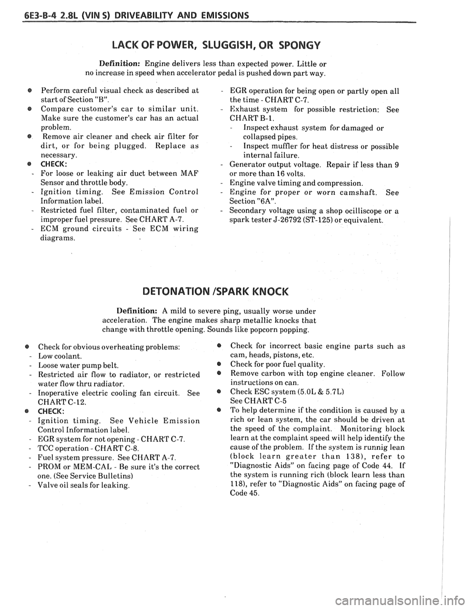
&E3-B-4 %.8L (VIN S) DRIVEABILITY AND EMISSIONS
LACK OF POWER, SLUGGISH, OR SPONGY
Definition: Engine delivers less than expected power. Little or
no increase in speed when accelerator pedal is pushed down part way.
Perform careful visual check as described at
- EGR operation for being open or partly open all
start of Section
"B". the time - CHART C-7.
e Compare customer's car to similar unit. - Exhaust system for possible restriction: See
Make sure the customer's car has an actual CHART
B-1,
problem.
@ Remove air cleaner and check air filter for
dirt, or for being plugged. Replace as
necessary.
@ CHECK:
- For loose or leaking air duct between MAF
Sensor and throttle body.
- Ignition timing. See Emission Control
Information label.
- Restricted fuel filter, contaminated fuel or
improper fuel pressure. See CHART A-7.
- ECM ground circuits - See ECM wiring
diagrams.
- Inspect exhaust system for damaged or
collapsed pipes.
- Inspect muffler for heat distress or possible
internal failure.
- Generator output voltage. Repair if less than 9
or more than 16 volts.
- Engine valve timing and compression.
- Engine for proper or worn camshaft. See
Section
"6A".
- Secondary voltage using a shop ocilliscope or a
spark tester
5-26792 (ST-125) or equivalent.
DETONATION ISPARK KNOCK
Definition: A mild to severe ping, usually worse under
acceleration. The engine makes sharp metallic knocks that
change with throttle opening. Sounds like popcorn popping.
@ Check for obvious overheating problems:
- Low coolant.
- Loose water pump belt.
- Restricted air flow to radiator, or restricted
water flow thru radiator.
- Inoperative electric cooling fan circuit. See
CHART C-12.
@ CHECK:
- Ignition timing. See Vehicle Emission
Control Information label.
- EGR system for not opening - CHART C-7.
- TCC operation - CHART C-8.
- Fuel system pressure. See CHART A-7.
- PROM or MEM-CAL - Be sure it's the correct
one. (See Service Bulletins)
- Valve oil seals for leaking.
@ Check for incorrect basic engine parts such as
cam, heads, pistons, etc.
@ Check for poor fuel quality.
@ Remove carbon with top engine cleaner. Follow
instructions on can.
@ Check ESC system (5.OL & 5.7L)
See CHART C-5
o To help determine if the condition is caused by a
rich or lean system, the car should be driven at
the speed of the complaint.
Monitoring block
learn at the complaint speed will help identify the
cause of the problem.
If the system is runnig lean
(block learn greater than
1381, refer to
"Diagnostic Aids" on facing page of Code 44.
If
the system is running rich (block learn less than
l18), refer to "Diagnostic Aids" on facing page of
Code 45.