1988 PONTIAC FIERO belt
[x] Cancel search: beltPage 1403 of 1825
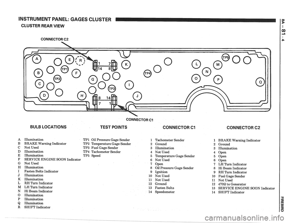
INSTRUMENT PANEL: GAGES CLUSTER I e
CLUSTER REAR VIEW
CONNECTOR 62
-
BULB LOCATIONS
CONNECTOR Cl
TEST POINTS CONNECTOR Cl
A Illumination TP1 Oil Pressure Gage Sender 1
B BRAKE Warning Indicator TP2 Temperature Gage Sender 2
C Not Used TP3 Fuel Gage Sender 3
D Illumination TP4 Tachometer Sender 4
E Illumination TP5 Speed 5
F SERVICE ENGINE SOON Indicator
6
G Not Used 7
H Illumination 8
I Fasten Belts Indicator 9
J Illumination 10
K Illumination 11
L RH Turn Indicator 12
M LH Turn Indicator 13
N Hi Beam Indicator 14
O Illumination
P Illumination
Q Illumination
R SHIFT Indicator Tachometer Sender
Ground
Illumination
Not Used
Temperature Gage Sender
Not Used
Open
Oil Pressure Gage Sender
Ignition
Not Used
Not Used
Ground
Fasten Belts
Speedometer
CONNECTOR 62
1 BRAKE Warning Indicator
2 Ground
3 Illumination
4 Open
5 Open
6 Open
7 LH Turn Indicator
8 Hi Beam Indicator
9 RH Turn Indicator
10 Fuel Gage Sender
11 Not Used
12
470R to Generator
13 SERVICE ENGINE SOON Indicator
14 SHIFT Indicator
Page 1405 of 1825
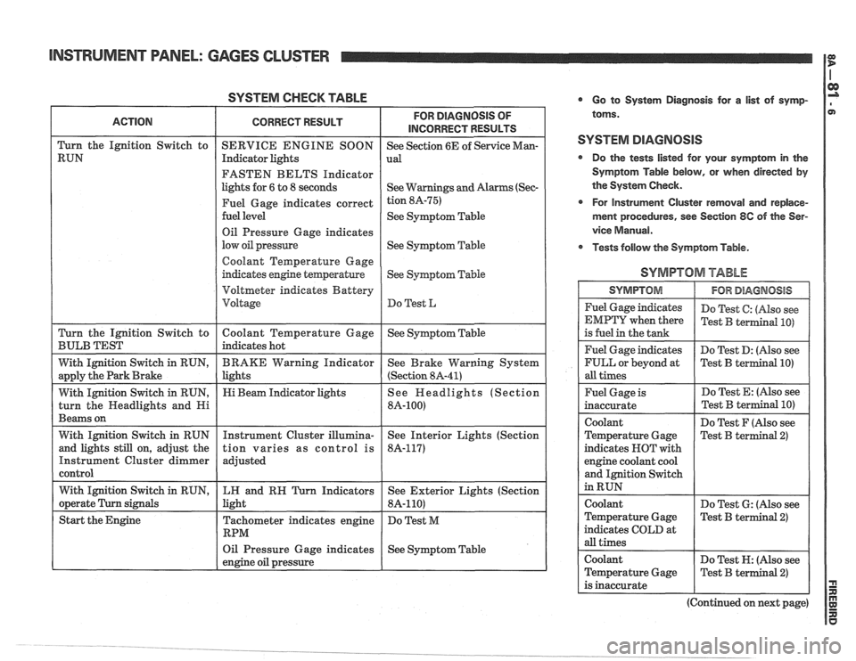
SYSTEM CHECK TABLE
FASTEN BELTS Indicator
lights for
6 to 8 seconds
See
Symptom Table
Oil Pressure Gage indicates
See
Syqtom Table
Coolant Temperature Gage
Voltmeter indicates Battery
Oil Pressure Gage indicates
See Symptom Table
engine oil pressure
L
Go to System Diagnosis for a list of symp-
toms.
SYSTEM DIAGNOSIS
Do the tests listed for your symptom in the
Symptom Table below, or when directed
by
the System Check.
r For Instrument Cluster removal and replace-
ment procedures, see Section
8C of the Ser-
vice
Manual.
Tests follow the Symptom Table.
SYMPTOM TABLE
I SYMPTOM 1 IFORDlAGMOSlS I
Fuel Gage indicates
EMPTY when there
is fuel in the tank
Fuel Gage indicates
FULL or beyond at
all times Do
Test
C: (Also see
Test
B terrnind PO)
Do Test D: (Nso see
Test
B terIllinal PO)
Fuel Gage is
inaccurate
Coolant
Temperature Gage
indicates NOT with
engine coolant cool
and Ignition Switch
in RUN Do
Test E: (Also see
Do Test F (Also see
Test B terminal
2)
coolant
Temperature Gage
indicates COLD at
all times Do
Test
6: (Also see
Test
B terminal 2)
Coolant Do Test N: (Also see
Temperature Gage
Test
B terminal 2)
is inaccurate
(Continued on next page)
Page 1406 of 1825
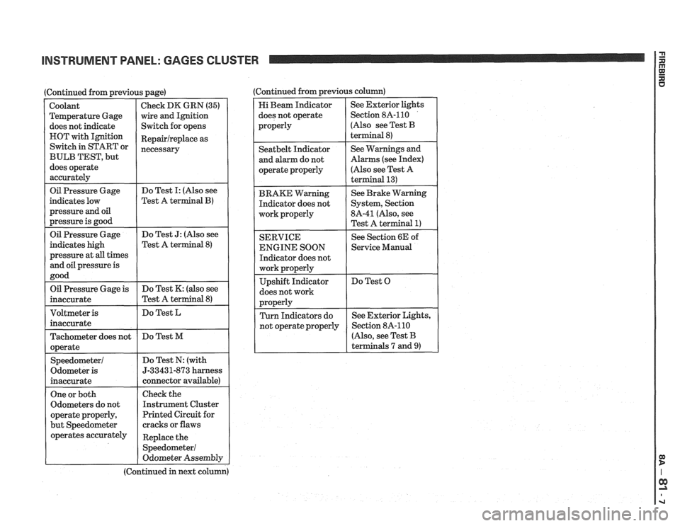
INSTRUMENT PANEL: GAGES CLUSTER
I Oil Pressure Gage
(Continued from previous page)
indicates low
pressure
and oil
pressure is good
Coolant
Temperature Gage
does not indicate
HOT with Ignition
Switch in START or
BULB TEST, but
does operate
accurately
Do Test I: (Also see
Test A
terminal B)
Check DK GRN (35)
wire and Ignition
Switch for opens
Repairlreplace as
necessary
Oil Pressure Gage
indicates high
pressure at
all times
and oil pressure is
good Do
Test
J: (Also see
Test A terminal
8)
Oil Pressure Gage is
inaccurate Do
Test K: (also see
Test A terminal
8)
Do Test L
Tachometer does not
operate
Speedometer1
Odometer is
inaccurate Do
Test M
Do Test N: (with
5-33431-873 harness
connector available)
One or both
Odometers do not
operate properly,
but Speedometer
operates accurately
I
Check the
Instrument Cluster
Printed Circuit for
cracks or flaws
Replace the
Speedometer1
Odometer Assembly
(Continued in next column) (Continued from previous
column)
Hi Beam Indicator
does not operate
properly See
Exterior lights
Section 8A-110
(Also see Test
B
terminal 8)
I operate properly
I
(Also see Test A
I
Seatbelt Indicator
and alarm do not
BRAKE Warning Indicator does not
work properly
I
See Warnings and
Alarms (see Index)
SERVICE
ENGINE SOON
Indicator does not
does not work See
Brake Warning
System, Section
8A-41 (Also, see
Test A terminal
1)
See Section 6E of
1 Service Manual
Do Test O
r
(Also, see Test B
terminals 7 and
9)
Page 1419 of 1825
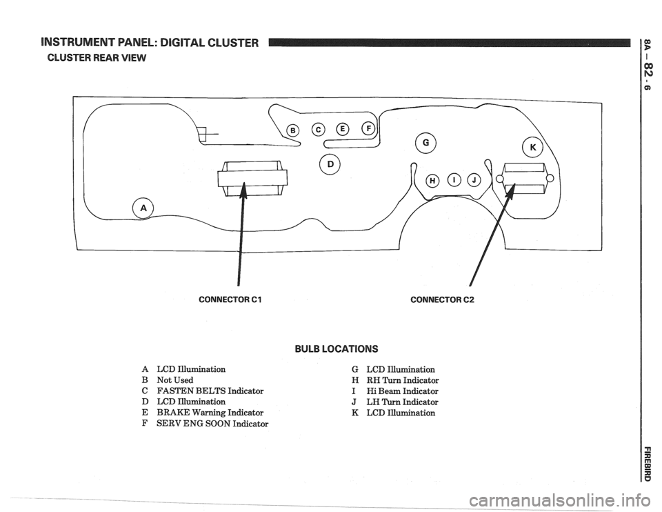
[NSTRUMENT WNEL: DIGITAL CLUSTER
CLUSTER REAR VlEW
CONNECTOR 61 CONNECTOR 62
BULB LOCATIONS
A LCD Illurnination
B Not Used
C FASTEN BELTS Indicator
D LCD Illumination
E BRAKE Warning Indicator
F SERV ENG SOON Indicator G
LCD Illumination
Indicator
Indicator
Indicator
K LCD Illumination
Page 1600 of 1825
LIGHTING SYSTEMS AND HORNS 8B-I
SECTION 8B
NG SYSTEMS AND HORNS
CONTENTS
........................... GENERAL DESCRIPTION 8B-1
Exterior Lights
....................... ................... Back-up Lights .. 8B- 1
Center High-Mounted Stoplight .................... 8B-1
Exterior Light Monitor .................................. 8B-1
............................ .................... Fog Lights .. 8B-1
Front Parking/Turn Signal Lights ................ 8B-2
............................... Hazard Flashers .. ........ 8B-2 .................................................... Headlights 8B-2
License Plate Lights ..................................... 8B-2
Light Switch ............................................... 8B-2
............... Rear Tail/Stop/Turn Signal Lights 8B-2
Sidemarker Lights ........................................ 8B-2
Turn Signals .......................................... 8B-2
......................... Underhood Light ... ........ 8B-2
Horns .......................................................... 8B-3
....................................... ON-CAR SERVICE 8B-3
Exterior Lights
............................................. Back-up Lights 8B-3
Center High-Mounted Stoplight .................... 8B-3
Fog Lights .................................................... 8B-4
Front Parking/Turn Signal Lights ................ 8B-4
Hazard Flasher .............................................. 8B-5
....................................................... Headlights 8B-5
License Plate Lights ..................................... 8B-7
............... Rear Tail/Stop/Turn Signal Lights 8B-8
.......................................... Sidemarker Lights 8B-8
................... ............... Turn Signal Flasher .. 8B-9
......................................... Underhood Light 8B-9
Horns ................................................................. 8B-9
REPLACEMENT BULB
.................................... SPECIFICATIONS 8B- 10
The following information, previously shown in this section,
has been moved to the sections shown.
Back-up Lights Switch
............................. ... ............................................................................ 7
................................................................................................................................. Fuse Block 8A
Ignition Switch ........................................................................................................................... 3B
Interior Lights
................................................................................................................... 8A, 8C
Neutral Start Switch ..................................................................................................................... 7
Parking Brake Warning Switch
......................... ... .................................................................... 5
........................................................................ Seat Belt, Key and Headlight Warning Alarm 8A
Stoplight Switch .......................... .. ............................................................................................... 5
Windshield
Wipers/Washers .................................................................................................... 8E
GENERAL DESCRIPTION
The exterior lighting system includes the
headlights (and headlight motors to raise or lower the
headlights), front
parkinghurn signal lights, front
cornering lights, fog lights, rear
tail/stop/turn signal
lights, back-up lights, license plate lights, center
high-mounted stoplight, and the underhood light; it
also includes all associated wiring, controls and related
hardware for these lights.
BACK-UP LIGHTS - The back-up lights are
next to the rear license plate. They will come on when
the transmission is shifted to Reverse. On cars with an
automatic transmission, the back-up lights are
activated by the neutral start switch. On cars with a
manual transmission, they are activated by a separate
back-up light switch on the transmission. For more
information, see Section 7.
CENTER HIGH-MOUNTED STOPLIGHT-
The center high-mounted stoplight, in the center of the
rear spoiler, will come on whenever the brake pedal is
pushed down. The light is powered separately from the rear
tail/stop/turn signal
lights through a separate
circuit in the stoplight switch (see Section
8A).
EXTERIOR LIGHT MONITOR - The Driver
Information Center, on cars so equipped, also monitors
certain front and rear lights. When a bulb burns out,
the message
"FRONT LAMP" or "REAR LAMP"
will appear in the DIC display, and a light will come
on to indicate which bulb has burned out. For more
information, see Section
8A.
FOG LIGHTS -The fog light switches are to the
left of the steering column on the edge of the
instrument panel. To use the fog lights, first turn on the
headlights or parking lights. Then, push the middle
switch (with the fog light symbol) to turn on the fog
lights. Push the left
("OFF") switch to turn off the fog
lights.
The fog lights should not be used as a substitute
for the headlights.
Switching to high-beam headlights will turn off
the fog lights; switching back to low-beams will turn
the fog lights on again.
Page 1609 of 1825
Adjust 2 . Filler panel 3 . Electrical connector
1 . Increase Current - Turn adjusting screw 4 . ~~l~/~~~~~
clockwise 5 . Horn
2 . Decrease Current . Turn adjusting screw
counterclockwise
Install or Connect
3 . Current adjustments should be made 1/4 turn
(90") at a time
Horn Assembly
Remove or Disconnect
1 . Six screws from filler panel behind front fascia on
driver's side 1
. Horn
2 . Bolt/screw
3 . Electrical connector
4
. Filler panel
5 . Six screws
Horn Relay
The horn relay is in the convenience center.
behind the instrument panel to the right of the steering
column
. To remove the relay. pull it straight out .
REPLACEMENT LIGHT BULBS
For exterior light replacement procedures. see the rest of this
section
. For interior light replacement procedures. see Section $A
and Section 8C .
EXTERIOR LIGHTS Trade No . ...................................................................................................................... Back-up Lights 1 156
Center
High-Mounted Stoplight ............................................................................................. 577
Front Barking/Turn Signal Eights ..................................................................................... 2057
Fog Lights
............................................................................................................................... H-3
Headlights ....................................................................................................................... H6054 ................................................................................................................ License Plate Lights 194
.................................................................................... Rear Tail/Stop/Turn Signal Lights 2057
Sidemarker Lights (Front and Rear) ...................................................................................... 194 ..................................................................................................................... Underhood Light 211
BNTERBOR LIGHTS Trade No .
......................................................................................... Air Conditioner/Heater Controls 194 .................................................................................................................. Ashtray & Lighter 194 .............................................................................................................. Cargo Compartment 561
................................................................................................ Cluster & Speedometer (Tach) 194 ..................................................................................................................... Console Ashtray 194 ............................................................................................................. Console Compartment 194
Courtesy Lights
..................................................................................................................... 194 ......................................................................................................................... Dome Light 561
Gear Selector Indicator
............................................................................................................ 74 .......................................................................................... Headlight High-Beam Indicator 194
Indicator Lights
..................................................................................................... Brake System Warning 194
With Gages
........................................................................................................................ 74
............................................................... Charging System Warning (except Rally Gages) 194 .................................................................................................................... Choke Warning
194
With Gages
........................................................................................................................ 74
...................................................................... Oil Pressure Warning (except Rally Gages) 194 ............................................................................................................ Seat Belt
Reminder 194
With Gages
.................................... ... ................................................................................. 74 ............................................................................................. Service Engine Soon Warning 194
With Gages
..................................................................................................................... 74 ............................................................ Temperature Gage Warning (except Rally Gages) 194
........................................................................................................................ Reading
Light 906 ............................................................................................................ Turn Signal Indicators 194
Page 1674 of 1825
MISCELLANEOUS ACCESSORIES 96-4
SCELLANEOUS ACCESSOR
General Description ................................. 9G-1
Rally Gages .................................................. 9G- 1
Tachometer ................................................. 9G- 1
Trip Odometer
............................................. 9G- 1
Electric Rear Window Defogger ................. 9G-2
Power Remote Control Rearview
Mirror ........................................................ 9G-2
Diagnosis .................................................... 9G-2
Rally Gages ............................................... 9G-2
Tachometer .................................... .... .... 9G-2
Electric Rear Window Defogger ................. 9G-2
Power Remote Control Rearview
Mirror ........................................................ 96-2
Dash and Console Mounted
Accessory Switches
................................. 9G-4
General Description .................................. 9G-4
Electronic Glare Control Mirror ................. 9G-4
On-Car Service ............................................. 9G-4
Rally Gages, Tach ....................................... 96-4.
Rear Window Defogger ............................ 96-4.
Power Remote Control Mirror .................... 9G-4
GENERAL BESCRIP"T0N
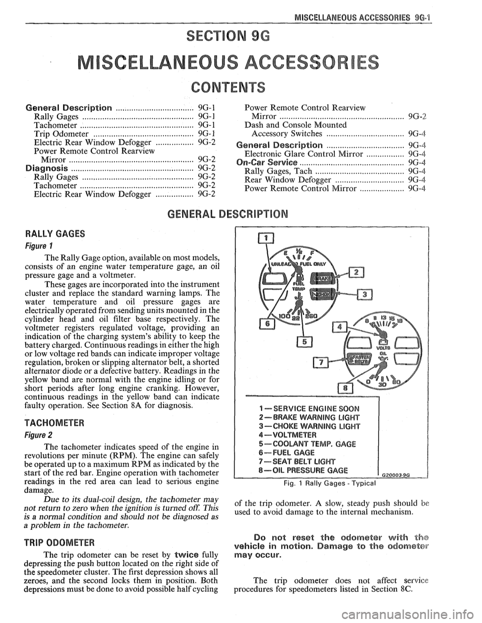
RALLY GAGES
Figure I
The Rally Gage option, available on most models,
consists of an engine water temperature gage, an oil
pressure gage and a voltmeter.
These gages are incorporated into the instrument
cluster and replace the standard warning lamps. The
water temperature and oil pressure gages are
electrically operated from sending units mounted in the
cylinder head and oil filter base respectively. The
voltmeter registers regulated voltage, providing an
indication of the charging system's ability to keep the
battery charged. Continuous readings in either the high
or low voltage red bands can indicate improper voltage
regulation, broken or slipping alternator belt,
a shorted
alternator diode
or a defective battery. Readings in the
yellow band are normal with the engine idling or for
short periods after long engine cranking. However,
continuous readings in the yellow band can indicate
faulty operation. See Section
8A for diagnosis.
TACHOMETER
Figure 2
The tachometer indicates speed of the engine in
revolutions per minute (RPM). The engine can safely
be operated up to a maximum RPM as indicated by the
start of the red bar. Engine operation with tachometer
readings in the red area can lead to serious engine
damage.
Due to its dual-coil design, the tachometer may
not return to zero when the ignition
is turned oft: This
is
a normal condition and should not be diagnosed as
a problem in the tachometer.
TRIP ODOMETER
The trip odometer can be reset by twice fully
depressing the push button located on the right side of
the speedometer cluster. The first depression shows all
zeroes, and the second locks them in position. Both
depressions must be done to avoid possible half cycling
I -SERVICE ENGINE SOON
2-BRAKE WARNING LIGHT
3-CHOKE WARNING LIGHT
4-VOLTMETER
5-COOUNT TEMP. GAGE
6-FUEL GAGE
7-SEAT BELT LIGHT
8-OIL PRESSURE GAGE G20003 9G
Fig. 1 Rally Gages - Typical
of the trip odometer. A slow, steady push should be
used to avoid damage to the internal mechanism.
Do not reset the odometer with the
vehicle in motion. Damage to the odometer
may occur.
The trip odometer does not affect service
procedures for speedometers listed in Section
8C.
Page 1688 of 1825
GENERAL INFORMATION - F STYLE IN-7
DEADENER APPLICATION TO
INSIDE OF DOOR OUTER PANEL
I I
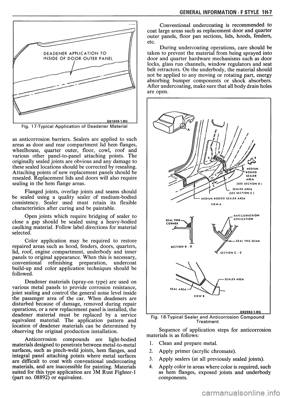
Fig. 17-Typical Application of Deadener Material
as anticorrosion barriers. Sealers are applied to such
areas as door and rear compartment lid hem flanges,
wheelhouse, quarter outer, floor, cowl, roof and
various other panel-to-panel attaching points. The
originally sealed joints are obvious and any damage to
these sealed locations should be corrected by resealing.
Attaching points of new replacement panels should be
resealed. Replacement lids and doors will also require
sealing in the hem flange areas.
Flanged joints, overlap joints and seams should
be sealed using a quality sealer of medium-bodied
consistency. Sealer used must retain its flexible
characteristics after curing and be paintable.
Open joints which require bridging of sealer to
close a gap should be sealed using a heavy-bodied
caulking material. Follow label directions for material
selected.
Color application may be required to restore
repaired areas such as hood, fenders, doors, quarters,
lid, roof, engine compartment, underbody and inner
panels to original appearance. When this is necessary,
conventional refinishing preparation, undercoat
build-up and color application techniques should be
followed.
Deadener materials (spray-on type) are used on
various metal panels to provide corrosion resistance,
joint sealing and control the general noise level inside
the passenger area of the car. When deadeners are
disturbed because of damage, removed during repair
operations, or a new replacement panel is installed, the
deadener material must be replaced by a service
equivalent material. The application pattern and
location of deadener materials can be determined by
observing the original production installation.
Anticorrosion compounds are light-bodied
materials designed to penetrate between metal-to-metal
surfaces, such as pinch-weld joints, hem flanges, and
integral panel attaching points where metal surfaces
are difficult to coat with conventional undercoating
materials, and are inaccessible for painting. Materials
suited for this type application are
3M Rust Fighter-1
(part no. 08892) or equivalent. Conventional
undercoating is recommended to
coat large areas such as replacement door and quarter
outer panels, floor pan sections, lids, hoods, fenders,
etc.
During undercoating operations, care should be
taken to prevent the material from being sprayed into
door and quarter hardware mechanisms such as door
locks, glass run channels, window regulators and seat
belt retractors. On the underbody, the material should
not be applied to any moving or rotating part, energy
absorbing bumper components or shock absorbers.
After undercoating, make sure that all body drain holes
are open.
SEAL THIS SEAM
SECTION
D - 0
ECTlON C . C
SEALER AREA
Fig. 18-Typical Sealer and Anticorrosion Compound
Treatment
Sequence of application steps for anticorrosion
materials is as follows:
1. Clean and prepare metal.
2. Apply primer (acrylic chromate).
3. Apply sealers (at all previously sealed joints).
4. Apply color in areas where color is required, such
as hem flanges, exposed joints and underbody
components.