1988 PONTIAC FIERO belt
[x] Cancel search: beltPage 1724 of 1825
DOORS - F STYLE 5H-11
loosened attachments to 10 to 14 N-m (90 to 125 in-lb)
torque.
1. Window Rotated
- Loosen up-stops (2 and 6),
adjust inner panel cam (8) as required and tighten
attaching screws. Adjust up-stops as required and
tighten attaching screws.
2. Window
Upper Edge Inboard or Outboard
-
Loosen the following attachments.
a. Filler at belt (1 and 10)
b. Rear
guide upper support lower bolts (Fig.
3 1, item 5)
Adjust rear guide as needed and tighten bolts.
Adjust and tighten filler assembly.
3. Window Too Far Forward or Rearward
- Loosen
filler assembly bolts (3 and 10). With glass in
half-down position, loosen bolts on rear guide
channel (7). Position glass to opening as needed
and tighten bolts. Position filler to glass and
opening as needed and tighten bolts.
4. Window Too Nigh or Low in Up Position -
Adjust front and rear up-travel stops (2 and 6) as
required.
5. Window Binds
- Ease of window operation and
stability depend to a great extent on the glass
stabilizers (5) at the beltline. Contact should be
enough to stabilize glass but not restrict window
operation.
The door window assembly consists of a
frameless piece of solid tempered safety plate glass. The
glass is riveted to the window regulator sash. Figure 24
illustrates a typical door with the trim panel and water
deflector removed. This figure identifies the hardware
parts of the door.
Removal
1. Remove
door trim panel and inner panel water
deflector.
2. Raise window to half-up position.
3. Punch out center pins of glass to sash channel
attaching rivets.
4. Remove rear guide channel through rear access
hole.
5. Remove up stop.
6. Using a 6.3 mm
(1/4") drill bit, drill out
attaching rivets on sash channel (Fig. 25).
7. Raise
glass to remove from sash channel and
remove glass from door.
Installation
1. Remove drilled
out rivets and shavings from
door.
2. Check rivet bushings
and retainers on glass for
damage. If necessary, remove bushings using a
flat-bladed tool covered with cloth body tape.
Install by snapping rivet retainer into bushing.
3. Lower glass into door and position on sash
channel so holes in sash line up with holes in
bushings and retainers.
4. Using rivet tooi J-29022 or equivalent, install
1/4" peel
type rivet (part no. 20184399 or
equivalent) to retain glass to sash channel (Fig.
25).
5. Install rear guide channel. 6.
Install front up stop to support on inner panel.
7. Before installing trim parts, check window
operation for performance and fit to roof rail
weatherstrip.
8. Install all remaining parts.
WINDOW SASH CHANNEL
Removal and Installation
1.
Remove door trim panel and water deflector.
2. Remove door glass as outlined in the window
removal portion of this section.
3. Slide sash channel off regulator rollers and
remove channel from door through rear access
hole.
4. To install, reverse removal procedure.
WINDOW REGULATOR AND REGULATOR
MOTOR
Removal
1. Remove door trim panel and inner panel water
deflector.
2. Raise window to half-up position and hold in
place by inserting rubber wedge door stops at
front and rear of window between window and
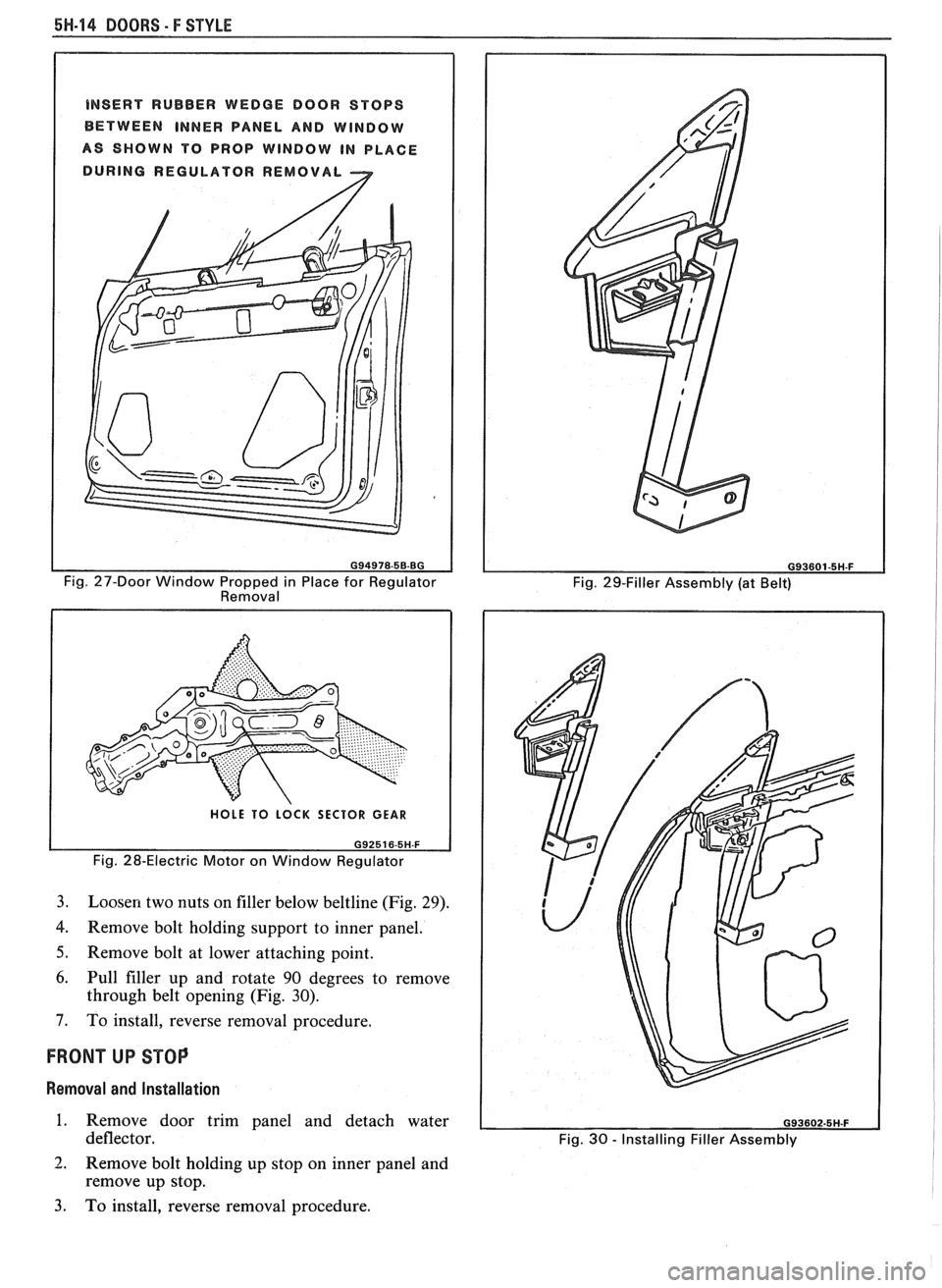
inner panel (Fig. 27).
3. Remove rear guide channel and inner panel cam
channel.
4. Punch out
center pins of regulator rivets; then
drill out rivets using 6.3 mm
(1/4") drill bit.
5. Move regulator rearward and disconnect wire
harness from motor (if present). Disengage roller
on regulator lift arm from glass sash channel.
6. Remove regulator through rear access hole.
CAUTION: If electric motor removal
from the regulator is required, the
sector gear
must be locked in position.
The regulator lift
arm is under tension
from the counterbalance spring and
could cause personal injury
if the
sector gear
is not locked in position.
7. Drill a
hole through the regulator sector gear and
backplate and install a bolt and nut to lock sector
gear in position (Fig. 28).
8. Using a 4.8 mm
(3/16") drill bit, drill out motor
attaching rivets and remove motor from
regulator.
Installation
1. To install motor to regulator, use rivet tool
J-29022 or equivalent, and install 4.8 mm
(3/16")
rivets or 4.8 mm (3/16") nuts and bolts. Remove
bolt and nut used to secure sector gear in position.
2. Place regulator through rear access hole into door
inner panel. If electric regulator is being installed,
connect wire connector to motor prior to
installing regulator to inner panel.
3. Locate lift arm roller into glass sash channel.
4. Using rivet tool J-29022 or equivalent, rivet
regulator to inner panel of door using
1/4"x0.
500" aluminum peel type rivets (part no. 9436175
Page 1726 of 1825
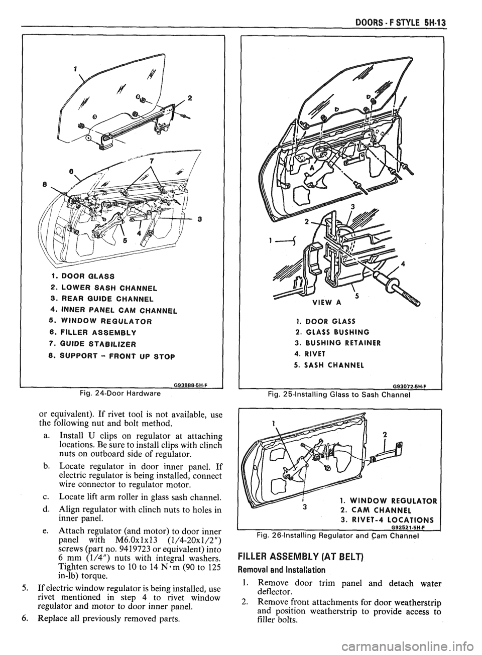
1. DOOR GLASS
2. LOWER SASH CHANNEL
3. REAR GUIDE CHANNEL
4. INNER PANEL CAM CHANNEL
6. WINDOW REGULATOR
6. FILLER ASSEMBLY
7. GUIDE STABILIZER
8. SUPPORT - FRONT UP STOP
G93888-5H-F
Fig. 24-Door Hardware
or equivalent). If rivet tool is not available, use
the following nut and bolt method.
a. Install
U clips on regulator at attaching
locations. Be sure to install clips with clinch
nuts on outboard side of regulator.
b. Locate regulator in door inner panel. If
electric regulator is being installed, connect
wire connector to regulator motor.
c. Locate lift arm roller in glass sash channel.
d. Align regulator with clinch nuts to holes in
inner panel.
e. Attach regulator (and motor) to door inner
panel with
M6.0~1~13 (1/4-20x1/2")
screws (part no. 9419723 or equivalent) into
6 mm (1/4") nuts with integral washers.
Tighten screws to
10 to 14 N-m (90 to 125
in-lb) torque.
5. If electric window regulator is being installed, use
rivet mentioned in step 4 to rivet window
regulator and motor to door inner panel.
6. Replace all previously removed parts.
DOORS - F STYLE 5H-13
1. DOOR GLASS
2. GLASS BUSHING
3. BUSHING RETAINER
4. RIVET
5. SASH CHANNEL
G93072-5H.F
Fig. 25-Installing Glass to Sash Channel
1. WINDOW REGULATOR
2. CAM CHANNEL
3. RIVET-4 L
Fig. 26-Installing Regulator and cam Channel
FILLER ASSEMBLY (AT BELT)
Removal and InstalJation
1. Remove door trim panel and detach water
deflector.
2. Remove front attachments for door weatherstrip
and position weatherstrip to provide access
tb
filler bolts.
Page 1727 of 1825
5H-14 DOORS - F STYLE
INSERT RUBBER WEDGE DOOR STOPS
BETWEEN
INNER PANEL AND WINDOW
AS SHOWN TO PROP WINDOW IN PLACE
DURING REGULATOR REMOVAL
2
Fig. 27-Door Window Propped in Place for Regulator
Removal
HOLE TO LOCK SECTOR GEAR
Fig. 28-Electric Motor on Window Regulator
3.
Loosen two nuts on filler below beltline (Fig. 29).
4. Remove bolt holding support to inner panel.
5. Remove bolt at lower attaching point.
6. Pull filler up and rotate 90 degrees to remove
through belt opening (Fig. 30).
7. To install, reverse removal procedure.
FRONT UP STOP
Removal and Installation
1. Remove door trim panel and detach water
deflector.
2. Remove bolt holding up stop on inner panel and
remove
up stop.
3. To install, reverse removal procedure.
Fig. 29-Filler Assembly (at Belt)
Fig.
30 - Installing Filler Assembly
Page 1736 of 1825
REAR QUARTERS - F STYLE 8H-1
SECTION 6H
REAR QUARTERS
NOTICE: The anti-theft label found on some major sheet metal, engines, and transmissions must be masked
prior to painting, rustproofing, undercoating, etc. The mask
must be removed following the above operations.
Failure to keep the label clean and readable may result in liability for violation of Federal Vehicle Theft Prevention
Standard, and subject the vehicle owner to possible suspicion that the part was stolen.
CONTENTS
Quarter Trim .................................................... 6H- 1
Lower Trim Finishing Panel ....................... 6H- 1
Body Lock Pillar Trim Finishing
Panel
., ....................................................... 6H- 1
Upper Trim Finishing Panel Insert ............. 6H- 1
....................................................... Speakers 6H- 1
Lift Window Upper Finishing
Molding
..................................................... 6H-2
....................... Upper Trim Finishing Panel 6H-2
QUARTER TRlM
QUARTER LOWER TRlM FINISHING PANEL
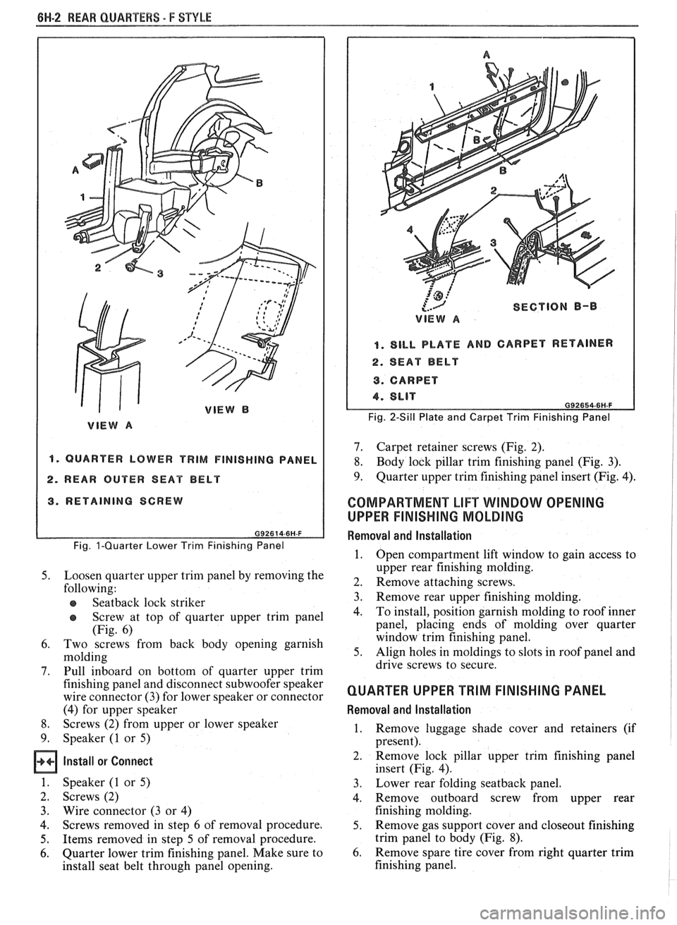
Removal and Installation (Fig. 1)
Remove body lock pillar finishing panel (Fig. 3).
Remove rear
seatback lock striker.
Remove retaining screw in rearward area of
quarter lower trim panel.
Remove rear screws from sill plate and carpet
retainer (Fig.
2).
Grasp quarter lower trim panel with hand; then
pull forward and down to disengage from
pinchweld flange at weatherstrip and quarter
upper trim finishing panel.
Remove seat belt through slot in trim panel.
Remove quarter lower trim finishing panel from
car by lifting up on rear portion of sill plate and
carpet retainer; then pull quarter trim rearward.
To install, place panel retaining slots under
quarter upper trim panel and apply upward
pressure to secure.
Position panel assembly to body. Thread lap and
shoulder belt through respective slots in panel.
Install attaching screws to secure panel to body.
Replace all previously removed components.
BODY LOCK PILLAR TRlM FINISHING PANEL
Removal and lnstallation (Fig. 3)
1. Remove trim panel attaching screws.
2. Using trim removing tool J-24595B, BT-7323A
or equivalent, carefully disengage nylon fasteners
that retain body lock pillar panel to quarter upper
trim finishing panel.
3. To install, reverse removal procedures. Spare
Tire Cover Trim Finishing
Panel
........................................................ 6H-3
Rear Stowage Compartment Box
Assembly
................................................... 6H-4
Luggage Shade Cover Assembly
................. 6H-4
Exterior Moldings
........................................... 6H-6
Fuel Tank Filler Door and Pocket
Assembly
....................................................... 6H-7
Spoiler Extension
............................ .. ........... 6H-7
QUARTER UPPER TRlM FINISHING PANEL
INSERT
Removal and Installation (Fig. 4)
1. Remove coat hook.
2. Grasp panel insert with hand and pull upward to
disengage retainers from cutout slots in quarter
upper trim finishing panel (Fig. 4).
3. To install, reverse removal procedures.
REAR QUARTER SPEAKERS
The rear quarter speakers are installed to a
speaker retainer. The retainer and speaker are then
attached to the quarter inner panel by screws.
Standard Speakers
Remove or Disconnect
1. Quarter upper trim finishing panel insert
2. Screws securing speaker retainer
3. Disconnect electrical
connector from speaker
4. Speaker
Install or Connect
1. Speaker to body
2. Electrical connector
3. Screws securing speaker to retainer
4. Quarter upper trim finishing panel insert
Subwoofer Speakers (2FS/FW/FX Styles)
Remove or Disconnect (Fig. 5)
1.
Quarter upper trim finishing panel insert (Fig. 4)
2. Body lock pillar trim finishing panel (Fig. 3)
3. Two rear screws from carpet retainer (Fig.
2)
4.
Quarter lower trim finishing panel
Page 1737 of 1825
661-2 REAR QUARTERS - F STYLE
"1 QUARTER LOWER TRIM FINISHING PANEL
2. REAR OUTER SEAT BELT
3. RETAINING SCREW
Fig. I-Quarter Lower Trim Finishing Panel
5. Loosen quarter upper trim panel by removing the
following:
e Seatback lock striker
@ Screw at top of quarter upper trim panel
(Fig. 6)
6. Two screws from back body opening garnish
molding
7. Pull inboard on bottom of quarter upper trim
finishing panel and disconnect subwoofer speaker
wire connector (3) for lower speaker or connector
(4) for upper speaker
8. Screws (2) from upper or lower speaker
9. Speaker (1 or 5)
Install or Connect
1. Speaker (1 or 5)
2. Screws (2)
3. Wire connector
(3 or 4)
4. Screws removed
in step 6 of removal procedure.
5. Items removed in step 5 of removal procedure.
6. Quarter lower trim finishing panel. Make sure to
install seat belt through panel opening.
'@ ,:'
{.-J SECTION B-I)
VIEW A
I. SILL PLATE AND CARPET RETAINER
4. SEAT BELT
9. CARPET
Fig. 2-Sill Plate and Carpet Trim Finishing Panel
7. Carpet retainer screws (Fig. 2).
8. Body lock pillar trim finishing panel (Fig. 3).
9. Quarter upper trim finishing panel insert (Fig. 4).
COMPARTMENT LIFT WINDOW OPENING
UPPER
FINISHING MOLDING
Removal and lnstallation
1. Open compartment lift window to gain access to
upper rear finishing molding.
2. Remove attaching screws.
3. Remove rear upper
finishing molding.
4. To
install, position garnish molding to roof inner
panel, placing ends of molding over quarter
window trim finishing panel.
5. Align holes in moldings to slots in roof panel and
drive screws to secure.
QUARTER UPPER TRIM FINISHING PANEL
Removal and Installation
1. Remove
luggage shade cover and retainers (if
present).
2. Remove
lock pillar upper trim finishing panel
insert (Fig. 4).
3. Lower
rear folding
seatback panel.
4. Remove outboard screw from upper rear
finishing molding.
5. Remove gas support cover and closeout finishing
trim panel to body (Fig.
8).
6. Remove spare tire cover from right quarter trim
finishing panel.
Page 1760 of 1825
ROOF - F STYLE 8H-1
SECTION 8H
ROOF
CONTENTS
Formed Headlining .......................................... 8H- 1
Interior Roof Attachments
.............................. 8H- 1
Interior Garnish Moldings .............................. 8H-2
Exterior Roof Moldings and
Attachments
.................................... .... ... 8H-3
Twin Lift-off Panel
......................................... 8H-3
Convertible Top
Top Operation
............................................ 8H-7
Header Inner Garnish
................................. 8H-8
"A" Pillar Inner Garnish
........... .;. .............. 8H-9
Header
"A" Pillar Seal ................................ 8H-9
Side Rail Seal and Retainer
......................... 8H-9
Main Pillar Seal and Retainer
..................... 8H-9
No.
5 Bow Seal .......................................... 8H-9
No. 1 Bow Garnish Molding
....................... 8H-9
Top Cover Assembly
.................................... 8H- 1 1
Side Stay Pads ............................................. 8H-13
Rear Stay Pads ............................................ 8H- 13
No.
1 and No. 2 Bows ................................. 8H- 13 NO. 3
BOW
.................................................... 8H-15
NO. 4 BOW ................................................ 8H-15
NO. 5 BOW ................................................. 8H-15
Top Stack Assembly Complete .................... 8H- 16
Quarter Inner Upper Trim Cap
.................. 8H- 17
Quarter Trim Panel
.................................... 8H- 17
Quarter Cap Belt Molding
........................... 8H- 17
Tonneau Panel Latch
................................. 8H- 17
Tonneau Release Solenoid
........................... 8H- 17
No. 5 Bow Release Handle
.......................... 8H- 19
No.
5 Bow Latch ....................................... 8H-19
Tonneau Panel
.......................................... 8H- 19
Tonneau Panel Seal
............................. ......... 8H-20
Deck Lid Spoiler ........................................ 8H-2 1
Center High Mount Stop Lamp .................. 8H-21
Deck Lid .................................................... 8H-21
Deck Lid Panel Seal
................................. 8H-22
Door Cap Belt Molding ............................... 8H-22
Front Belt Retractor Assembly ................... 8H-22
FORMED HEADLINING 1. Load the headlining through the rear
The one-piece formed headlining (Fig. 1) consists
of a molded fiberglass substrate covered with a foam
and cloth facing. The one-piece construction requires
the headlining be serviced as a complete assembly.
The headlining is held partially in place by
retaining fasteners located in the headlining which fit
into slots in the roof panel. Final attachment is
accomplished when the interior moldings and
attaching screws that retain the sunshade brackets,
dome lamp base and coat hooks are installed.
Removal
1. Remove the following items:
e Back body opening upper garnish molding
r Windshield side upper garnish molding (1,
Fig. 3 or
6)
e Rear vertical garnish molding
a Windshield header courtesy reading and
console lamp
e Sunshades
e Partially remove shoulder belt bezel and
belt
a Coat hooks and rail panel inserts
2. Grasp headlining assembly with both hands at
outer edges and move to the right of centerline to
disengage fastener assemblies from front
attaching slots.
3. Remove headlining assembly through right front
door.
lnstallation
Care must be exercised when loading assembly.
Excessive flexing may result in damage. compartment
opening.
2. Align headlining with cutouts for sunshades and
dome lamp and install sunshade brackets and
dome lamp base. Do not tighten sunshade bracket
and dome lamp attaching retainers completely
until headlining is aligned properly at all
hardware attaching locations.
3. Align headlining to roof inner panel with
fasteners positioned over holes in roof panel and
using palm of hand, push up on headlining at
fastener locations.
4. Install all previously removed hardware and
interior moldings.
INTERIOR ROOF ATTACHMENTS
DOME LAMPS
The dome lamp operates in conjunction with the
door jamb switch and/or the
headlamp switch. The
dome lamp harness extends up the right windshield
pillar, outboard of the sunshade support and across the
roof inner panel to the dome lamp.
Removal and Installation (Typical)
1. Grasp lens portion of dome lamp assembly,
squeeze and pull down to remove.
2. Remove bulb from terminal clips.
3. Remove retainers from studs.
4. Disengage wire harness from lamp housing and
remove dome lamp housing.
5. To install dome lamp assembly, reverse removal
procedure.
Page 1776 of 1825
ROOF - F STYLE 8H-17
a Inspect
Top stack assembly fit to body.
Adjust
Top stack as necessary by loosening nuts
and shifting top stack
6. Tighten nuts to 10
Nem (13 ft-lbs)
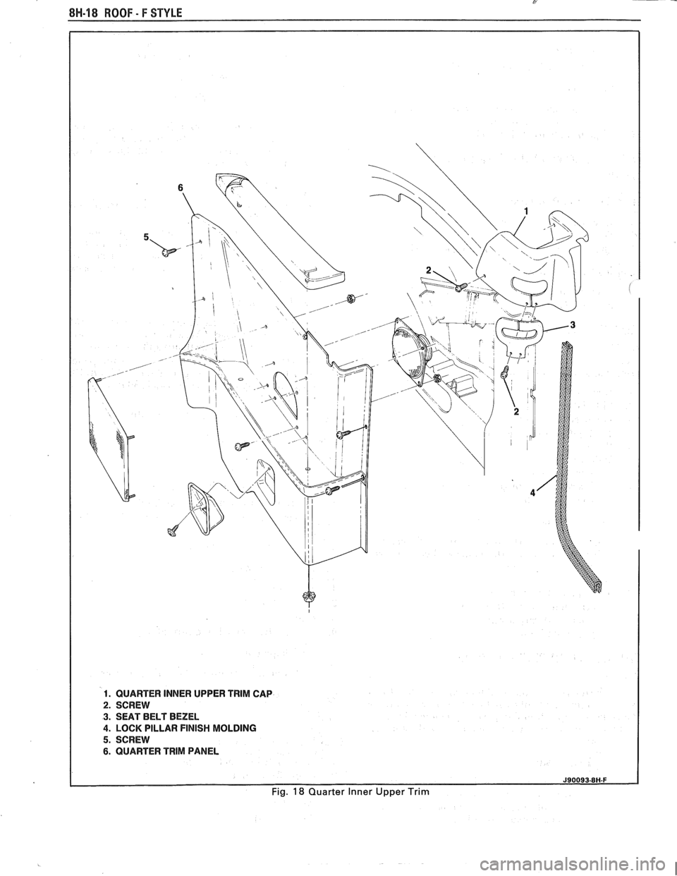
QUARTER INNER UPPER TRlM CAP
Fig. 18
Remove or Disconnect
1. Lower top completely.
2. Screws
(2)
3. Quarter
inner upper trim cap and bezel
Install or Connect
.. Quarter inner upper trim cap and bezel
2. Screws (2)
QUARTER TRlM PANEL
Fig. 18
Remove or Disconnect
1. Rear seat cushion
2. Sill
plate and carpet retainer
3. Quiarter inner upper trim cap
4. Lock pillar finish molding
5. Screws
6. Pull quarter trim panel out and disconnect
speaker wire connector
7. Push seat belt through slot in trim panel
8. Quarter trim panel
Install or Connect
.. Position quarter trim panel to body. Thread seat
belt through slot in trim panel and connect wire
connector to speaker.
2. Screws
3. Lock pillar finish molding
4. Quarter
inner upper tirm cap
5. Sill plate and carpet retainer
6. Rear seat cushion
QUARTER CAP BELT MOLDING
Fig. 19
The quarter cap belt moldings are attached to the
body by screws and adhesive tape shown in Figure 19.
The quarter cap belt molding can be removed from the
body with the use of a hot air gun to break the adhesive
tape bond.
Important
When removing or installing quarter cap
belt molding, care should be exercised.
Adjacent finishes should be protected to
prevent damage to finish.
e Proper tools and care should be used to
guard against molding damage.
Remove or Disconnect
1.
Quarter inner upper trim cap
2. Screws (1)
3. Quarter cap belt molding using hot air gun held
about 300 mm (12") from the surface. Apply heat
in a circular motion and carefully lift the molding
from the body surface.
e Wash quarter panel area with soap and
water and wipe dry.
Wipe quarter panel and adhesive side of
molding with a clean rag using oil-free
Naptha or alcohol to remove all traces of
adhesive tape from quarter panel and back
side of molding.
Install or Connect
1.
Apply a double-coated adhesive tape such as 3M
Super Automotive Attachment Tape (Part
Number 4210) or equivalent to the molding.
2. Quarter cap belt molding warm quarter panel
with heat lamp or heat gun about 21°C (70°F).
Align molding and press firmly in place.
3. Screws (1)
4. Quarter inner trim cap (see procedure)
TONNEAU PANEL LATCH
Fig, 20
Remove or Disconnect
1. Quarter trim panel (see procedure)
2. Cable (1)
3. Screws (3)
4. Latch (4)
Install or Connect
1. Latch (4)
2. Screws (3)
3. Cable (1)
4. Quarter trim panel (see procedure)
Important
Latch as required and retighen screws.
TONNEAU RELEASE SOLENOID
Fig, 20
Remove or Disconnect
1. Quarter trim panel (see procedure)
2. Cable from latch p
3. Wire connector (6)
4. Screws (7)
5. Solenoid (8)
Page 1777 of 1825
8H-18 ROOF - F STYLE
1. QUARTER INNER UPPER TRlM CAP
2. SCREW
3. SEAT BELT BEZEL
4. LOCK PILLAR FINISH MOLDING
5. SCREW
6. QUARTER TRlM PANEL
Fig. 18 Quarter Inner Upper Trim