1988 PONTIAC FIERO belt
[x] Cancel search: beltPage 426 of 1825

ENGINE COOLING 6B-15
1. 27 N-m (20 LBS. FT.)
2. 34 N.m (25 LBS. FT.)
Fig. 602 Thermostat - V.I.N. E, F and 8
ELECTRIC COOLING FAN
CAUTION: Keep hands, tools, and
clothing away from engine cooling fan
to help prevent personal injury. This
fan is electric and can come on
whether or not the engine is running.
The fan can start automatically in
response to a heat sensor with the
ignition in the "On" position.
Remove or Disconnect
1. Negative battery cable.
2. Harness from fan motor and fan frame.
3. Fan
frame to radiator support attaching bolts.
4. Fan and frame assembly.
Install or Connect
1. Fan and frame assembly.
2. Fan frame to radiator support attaching bolts and
torque to specification.
3. Harness
to fan frame and fan motor.
4. Negative battery cable.
Inspect
For proper completion of repairs.
For operation of fan motor.
WATER PUMP
Remove or Disconnect
1. Battery negative cable at battery.
2. Cooling system.
3. If equipped with M.F.I., remove air intake tube
and mass air flow sensor.
4. Fan and radiator upper support, as applicable.
5. Serpentine belt.
6. Generator upper and lower brackets, A/C brace
and bracket and, if equipped, power steering
pump lower bracket from water pump and swing
aside.
7. Radiator lower hose and heater hose from water
Pump.
8. Water pump to block attaching bolts and remove
water pump.
Install or Connect
s If installing a new water pump, transfer
heater hose fitting from old unit.
With clean sealing surfaces on both block and water
pump, install water pump to block with new gaskets
and retain with attaching bolts. Torque to specifica-
tions. (V6 small bolt
10N.m, 7 lb. ft., large bolt and
nut 20
N-m, 15 lb. ft.) (V8-40 Nsm, 30 lb. ft.)
Radiator lower hose and heater hose to water pump
and torque clamps to 2
N.m (20 lb. in.).
Generator upper and lower brackets and, if
equipped, the power steering pump lower bracket to
the water pump. Torque bolts to 41
N.m (30 lb. in.).
Serpentine belt.
If equipped with M.F.I., install air intake tube
and mass air flow sensor.
Fan and radiator upper support, as applicable.
Battery negative cable.
Fill cooling system with an ethylene glycol
antifreeze and water mixture of
50/50.
Start engine and run, with radiator cap removed,
until radiator upper hose becomes hot
(thermostat open).
With engine idling, add coolant to radiator until
level reaches bottom of filler neck.
Cap, making sure arrows line up with overflow
tube.
Fig. 603 Fan Mounting V.I.N. E, S (All) F, 8 (wlo A/C)
Page 429 of 1825
88-18 ENGINE COOLING
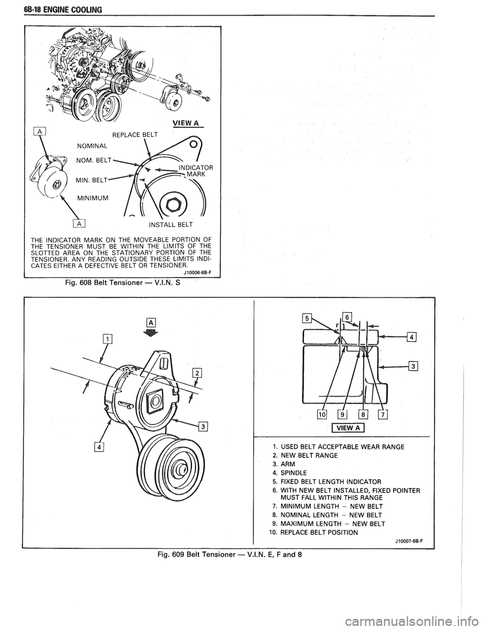
THE INDICATOR MARK ON THE MOVEABLE PORTION OF
THE TENSIONER MUST BE WITHIN THE LIMITS OF THE
SLOTTED AREA ON THE STATIONARY PORTION OF THE
TENSIONER. ANY READING OUTSIDE THESE LIMITS INDI-
CATES EITHER A DEFECTIVE BELT OR TENSIONER.
Fig. 608 Belt Tensioner - V.I.N. S
1. USED BELT ACCEPTABLE WEAR RANGE
2. NEW BELT RANGE
5. FIXED BELT LENGTH INDICATOR
6. WITH NEW BELT INSTALLED, FIXED POINTER
MUST FALL WITHIN THIS RANGE
7. MINIMUM LENGTH - NEW BELT
8. NOMINAL LENGTH - NEW BELT
9. MAXIMUM LENGTH - NEW BELT
10. REPLACE BELT POSITION
Fig. 609 Belt Tensioner - V.I.N. E, F and 8
Page 430 of 1825
ENGINE COOLING 6B-19
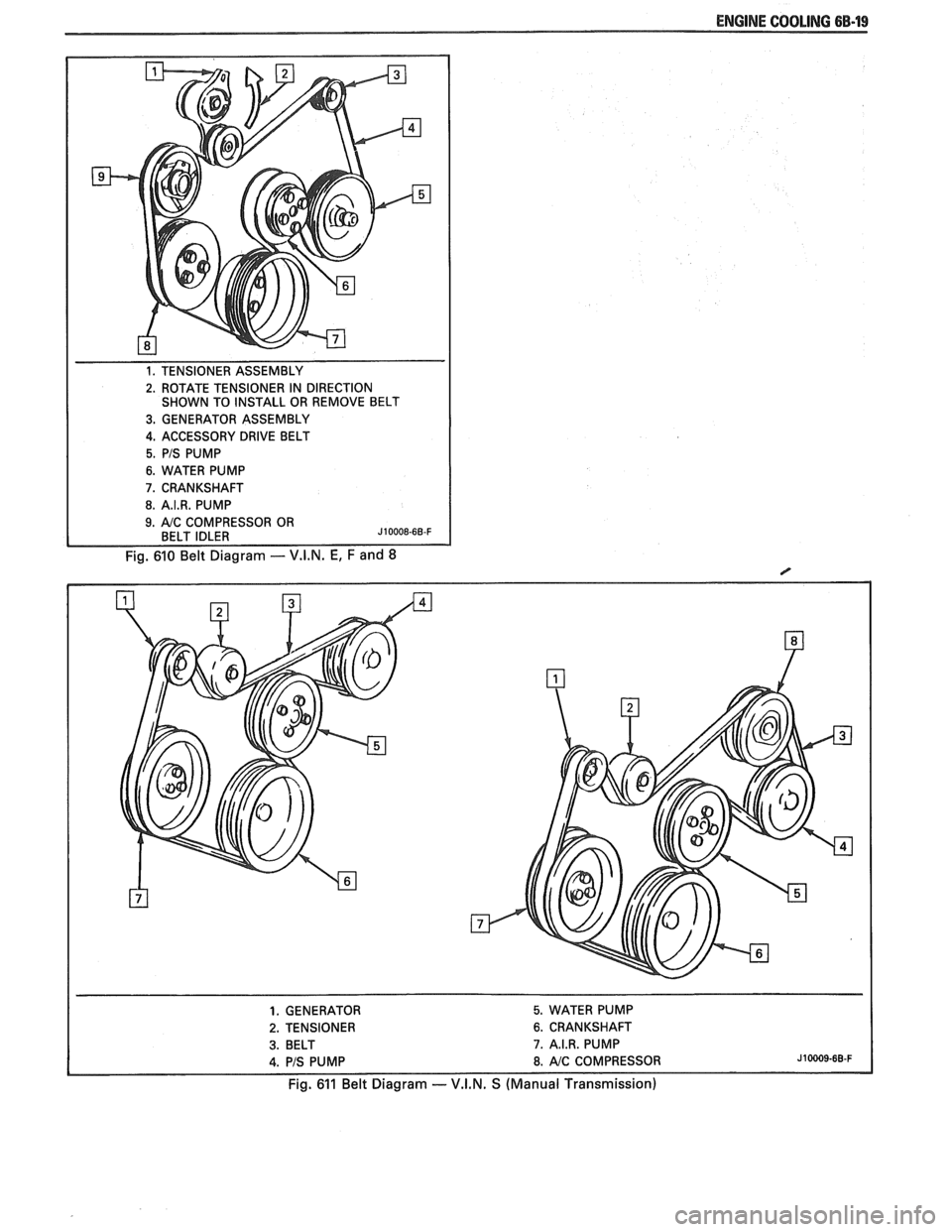
1. TENSIONER ASSEMBLY
2. ROTATE TENSIONER IN DIRECTION
SHOWN TO INSTALL OR REMOVE BELT
3. GENERATOR ASSEMBLY
4. ACCESSORY DRIVE BELT
5. PIS PUMP
6. WATER PUMP
7. CRANKSHAFT
8. A.I.R. PUMP
Fig. 610 Belt Diagram - V.I.N. E, F and 8
1. GENERATOR 5. WATER PUMP
2. TENSIONER 6. CRANKSHAFT
3. BELT 7. A.I.R. PUMP
4. PIS PUMP 8. AIC COMPRESSOR J10009-68-F
Fig. 611 Belt Diagram -- V.I.N. S (Manual Transmission)
Page 431 of 1825
6B-20 ENGINE COOLING
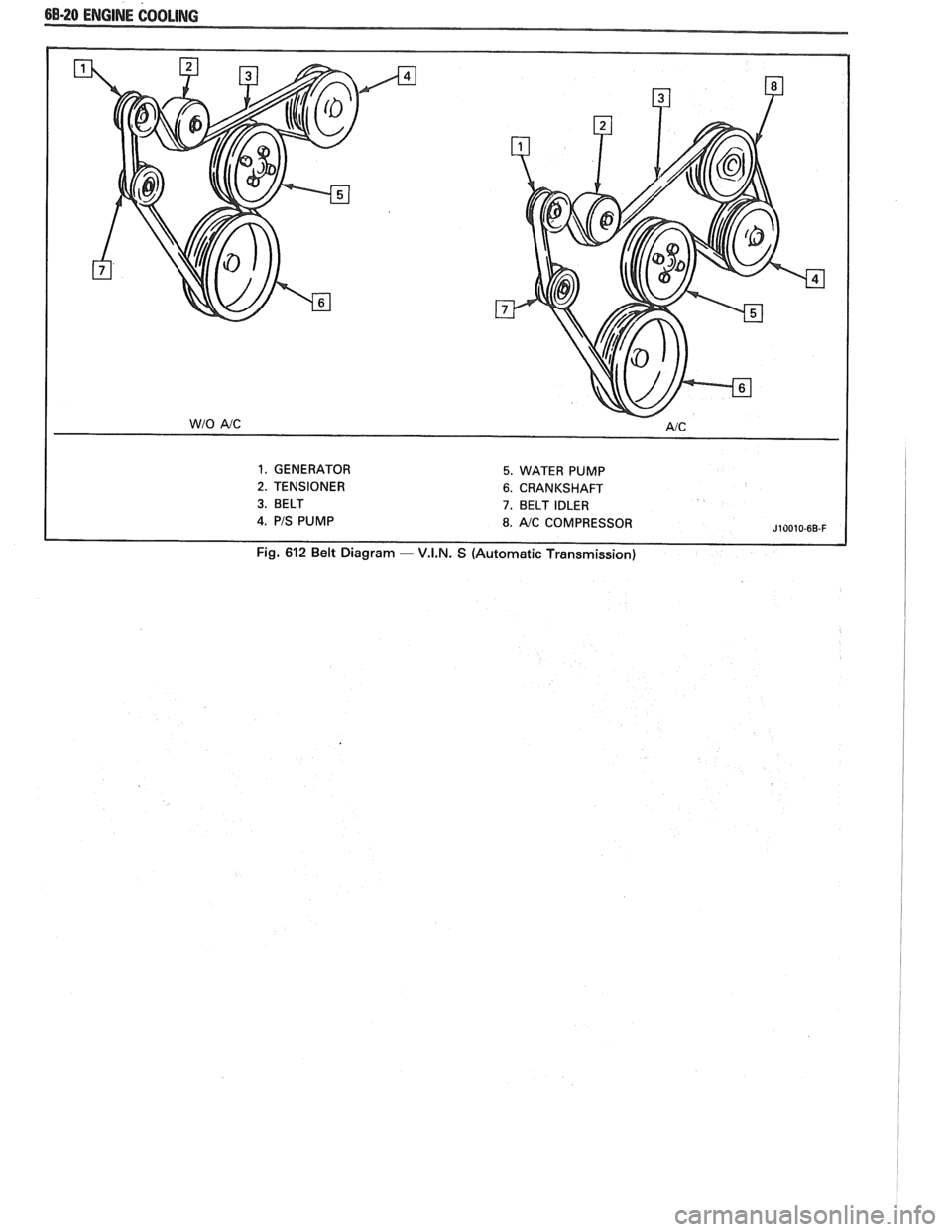
1. GENERATOR 5. WATER PUMP
2. TENSIONER 6. CRANKSHAFT
3. BELT 7. BELT IDLER
J10010-6B-F
Fig. 612 Belt Diagram - V.I.N. S (Automatic Transmission)
Page 445 of 1825
6D1-2 BA'TTERY
3. The
vehicle's electrical load is more than the
generator output, particularly with the addition
of aftermarket equipment.
4. Defects in the charging system such as electrical
shorts, slipping fan belt, faulty generator, or
faulty voltage regulator.
5. Battery abuse, including failure to keep the
battery cable terminals clean and tight, or loose
battery hold-down. See "Service Procedures" for
torque specifications.
6. Mechanical problems in the electrical system,
such as shorted or pinched wires.
Electrolyte Freezing
The freezing point of electrolyte depends on its
specific gravity. Since freezing may ruin a battery, it
should be protected against freezing by keeping it in a
charged condition.
Carrier and Hold-Down
The battery carrier and hold-down clamp should
be clean and free from corrosion before installing
battery.
The carrier should be in sound condition, to hold
the battery securely and keep it level. Make certain
there are no parts in the carrier before installing
battery.
To prevent the battery from shaking
in its carrier,
the hold-down bolts should be tight, but not
overtightened.
Built-In Hydrometer
The sealed battery has a built-in, temperature
compensated hydrometer in the top of the battery. This
hydrometer is to be used with the following diagnostic
procedure.
When observing the hydrometer, make sure that
the battery has a clean top. A light may be required,
if the lighting is poor.
Under normal operation, two indications can be
observed (see Fig.
4).
1. GREEN DOT VISIBLE
Any green appearance is interpreted as a "green
dot" and the battery
is ready for testing.
2. DARK; GREEN DOT NOT VISIBLE
If there is a cranking complaint, the battery
should be tested as described in the "Diagnosis"
section. The charging and electrical system
should also be checked at this time.
Occasionally, a third condition may appear:
3. CLEAR OR LIGHT YELLOW
This means the fluid level is below the bottom of
the hydrometer. This may have been caused by
excessive or prolonged charging, a broken case,
excessive tipping, or normal battery
wearout.
Finding a battery in this condition may indicate
high charging voltages caused by a faulty
charging system. Therefore, the charging and
electrical systems may need to be checked. If a
cranking complaint exists and is caused by the
battery, it should be replaced.
BATTERY
1. VISUAL INSPECTION
Check for obvious damage, such as cracked or
broken case or cover, that could permit loss of
electrolyte. If obvious damage is noted, replace
the battery. Determine cause of damage and
correct as needed. If not, proceed to step 2.
2. HYDROMETER CHECK
a. GREEN
DOT VISIBLE
- Go To Step 3
b. DARK;
GREEN DOT NOT VISIBLE -
Charge the battery as outlined under
"Charging Procedure" section and proceed
to Step 3.
3. LOAD TEST
Load testing may require use of battery side
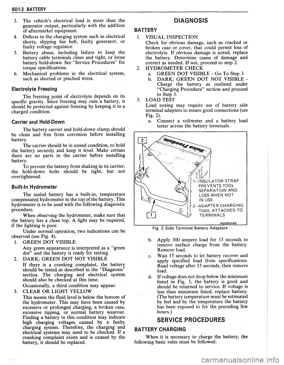
terminal adapters to insure good connections (see
Fig. 2).
a. Connect
a voltmeter and a battery load
tester across the battery terminals.
INSULATOR STRAP
PREVENTS TOOL
SEPARATION AND
LOSS WHEN NOT
2-ADAPTER CHARGING
TOOL ATTACHED TO
TERMINALS
Fig. 2 Side Terminal Battery Adapters
b. Apply 300 ampere load for 15 seconds
to
remove surface charge from the battery.
Remove load.
c. Wait
15 seconds to let battery recover and
apply specified load from specifications.
Read voltage after 15 seconds, then remove
load.
d. If
voltage does not drop below the minimum
listed in Fig. 3, the battery is good and
should be returned to service. If voltage is
less than minimum listed, replace battery.
(The battery temperature must be estimated
by feel and by the temperature the battery
has been exposed to for the preceding few
hours.)
SERVICE PROCEDURES
BATTERY CHARGING
When it is necessary to charge the battery, the
following basic rules must be followed:
Page 464 of 1825
CHARGING SYSTEM 6D3-1
SECTION 6D3
CHARG NG SYSTEM
CONTENTS
General Description ................................. 6D3- 1 Charging System ........................................ 6D3- 1
.......................................... Charging System - CS ............................... 6D3- 1 On-Car Service 6D3-2
................................................... Diagnosis .. 6D3- 1 Generator 6D3-3 ...................... ......................... ............................................. 6D3- 1 Specifications 6D3-3 Service Procedures .................................. Unit Repair .. 6D3-4-6 ............................... ............
GENERAL DESCRIPTION
The engine electrical system includes the battery,
ignition (primary and secondary), starter (and related
wiring) and the generator (and related wiring).
Diagnostic charts (see Section 6D) will aid in
trouble-shooting system faults. When a fault is traced
to a particular component, refer to that components'
section of the service manual.
CHARGING SYSTEM-CS
The CS Charging System has several sizes
available, including the CS-130 and CS-144. The
number (130 or 144) denotes the
OD in mm of the
stator laminations.
CS generators use a new type regulator and a
diode trio is not used. A delta stator, rectifier bridge,
and rotor with slip rings and brushes are electrically
similar to earlier generators. A conventional pulley and
fan is used and, on the CS-130, an internal fan cools the
slip ring end frame, rectifier bridge and regulator.
Unlike three-wire generators, the CS-130 and
CS-144 may be used with only two connections
-
battery positive and an "L" terminal to the charge
indicator bulb. Use of "P",
"F", and "S" terminals is
optional. The "P" terminal is connected to the stator,
and may be connected externally to
a tachometer or other
device. The
"F" terminal is connected internally
to field positive, and may be used as a fault indicator.
The "S" terminal may be connected externally to a
voltage, such as battery voltage, to sense voltage to be
controlled.
As on other charging systems, the charge
indicator lights when the switch is closed, and goes out
when the engine is running. If the charge indicator is
on with the engine running, a charging system defect
is indicated. For all kinds of defects, the indicator will
glow at full brilliance, not "half lit". Also, the charge
indicator will be on with the engine running if system
voltage is too high or too low. The regulator voltage
setting varies with temperature, and limits system
voltage by controlling rotor field current.
This regulator switches rotor field current on and
off at a fixed frequency of about 400 cycles per second.
By varying the on-off time, correct average field
current for proper system voltage control is obtained.
At high speeds, the on-time may be 10% and the
off-time 90%. At low speeds, with high electrical loads,
on-off time may be 90% and
lo%, respectively.
No periodic maintenance on the generator is
required.
DIAGNOSIS
SERVICE PROCEDURES
CHARGING SYSTEM
The generator does not require periodic
lubrication. The rotor shaft is mounted on ball bearings
at the drive end and roller bearings at the slip ring end.
Each contains a permanent grease supply. At periodic
intervals, check mounting bolts for tightness and adjust
belt tension (see Section
6B), if applicable.
e When adjusting belt tension, apply pressure at
center of generator, never against either end
frame.
GENERATOR BENCH CHECK-CS
To check generator in a test stand, remove as
specified in On-Car Service and proceed as follows: 1.
Make connections as shown in Figure
lH, except
leave the carbon pile disconnected. The ground
polarity of generator and battery must be the
same. The battery must be fully charged. Use a
30-500
OHM resistor between battery and "L"
terminal.
2. Slowly increase generator speed and observe
voltage.
3. If the voltage is uncontrolled and increases above
16.0 volts, the rotor field is shorted, the regulator
is defective, or both.
A shorted rotor field coil can
cause the regulator to become defective. NOTE:
The battery must be fully charged when making
this test.
Page 488 of 1825
DRIVEABILITY AND EMISSIONS 5.OL (VIN E) 6E2-3
........ FUEL METER COVER ASSEMBLY C2-7
FUEL INJECTOR ASSEMBLIES .......... C2-8
FUEL METER BODY ASSEMBLY ......... C2-9
..... THROTTLE POSITION SENSOR (TPS) C2-10
IDLE AIR CONTROL (IAC) VALVE ........ 62-1 1
THROTTLE BODY ASSEMBLY
.......... C2-11
MINIMUM IDLE SPEED CHECK .......... C2-12
... THROTTLE BODY INJECTION (TBI) UNIT C2-13
FUEL
HOSEIPIPE ASSEMBLIES .......... C2-13
Materials ...................... C2-13
Fuel Line Repair .................. C2-13
FUEL PUMP RELAY .................. C2-13
............... OILPRESSURESWITCH C2-13
PARTS INFORMATION ................. C2-14
Idle Air Control (IAC) Valve Check
Chart C-2C
..................... C2-16
SECTION C3
EVAPORATIVE EMISSION CONTROL SYSTEM
GENERAL DESCRIPTION
............... C3-1
........................ PURPOSE C3-1
VAPOR CANISTER
................... C3-1
EVAPORATIVE EMISSION SYSTEM
....... C3-1
IN-TANK PRESSURE CONTROL VALVE
. . C3-2
.... RESULTS OF INCORRECT OPERATION C3-2
........................ DIAGNOSIS C3-2
VISUAL CHECK OF CANISTER
.......... C3-2
CANISTER PURGE SOLENOID
.......... C3-2
ON-CAR SERVICE ................. C3-2
FUEL VAPOR CANISTER
R/R ............ C3-2
CANISTER HOSES
.................... C3-2
PARTS INFORMATION ................ C3-2
Canister Purge Valve Check
Chart C-3
...................... C3-4
SECTION
C4
IGNITION SYSTEM I EST
GENERAL DESCRIPTION
............... C4-1
PURPOSE ........................ C4-1
OPERATION ...................... C4-1
.. DIAGNOSIS ................... ... C4-1
RESULTS OF INCORRECT EST OPER ...... C4-1
HOW CODE 42 IS DETERMINED ....... C4-2
CODE12 ........................ C4-2
CHECKING EST PERFORMANCE ........ C4-2
ON-CAR SERVICE .................... C4-2
SETTINGTIMING .................. C4-2
PARTS INFORMATION ................ C4-2
Ignition System Check
Chart C-4
................... .. . C4-4
SECTION C5
ELECTRONIC SPARK CONTROL (ESC) SYSTEM
GENERAL DESCRIPTION
................ C5-1
PURPOSE ..*...................... C5-1
OPERATION
....................... C5-1
DIAGNOSIS
......................... C5-1
RESULTS OF INCORRECT ESC OPERATION
. C5-1
ON-CAR SERVICE
..................... C5-1 ESC
KNOCK SENSOR
................ C5-1
ESCMODULE
...................... C5-1
PARTS INFORMATION ................. C5-2
Electronic Spark Control (ESC) System Check
Chart C-5
...................... C5-4
SECTION C6
AIR INJECTION REACTION (A.I.R.) SYSTEM
GENERAL DESCRIPTION
............... C6-1
PURPOSE
.*....................... C6-1
OPERATION
...................... C6-1
AIR CONTROL PEDES VALVE .......... C6-1
RESULTS OF INCORRECT OPERATION
.... C6-2
DIAGNOSIS
........................ C6-2
OPERATIONAL CHECKS
.....*........ C6-2
AirPump ...................... C6-2
Hoses and Pipes
................. C6-3
Check Valve
.................... C6-3
ON-CAR SERVICE
.................... C6-3
DRIVEBELT ...................... C6-3
AIR INJECTION PUMP
............... C6-3
AIR INJECTION CONTROL
(PEDES) VALVE
.................. C6-3
AIR INJECTION CHECK VALVE ......... C6-4
PARTS INFORMATION
................ C6-4
AIR Management Check
. Pedes Valve
Chart C-6
..................... C6-6
SECTION C7
EXHAUST GAS RECIRCULATION (EGR) SYSTEM
GENERAL DESCRIPTION
............... C7-1
PURPOSE
........................ C7-1
OPERATION
...................... C7-1
EGRCONTROL
..................... C7-1
NEGATIVE BACKPRESSURE VALVE
...... C7-1
EGR VALVE IDENTIFICATION
.......... C7-2
RESULTS OF INCORRECT OPERATION
.... C7-2
DIAGNOSIS
......................... C7-2
ON-CAR SERVICE
..................... C7-2
EGRVALVE
....................... C7-2
EGR Manifold Passage
............. C7-2
EGR CONTROL SOLENOID
............. C7-3
PARTS INFORMATION
................. C7-3
Exhaust Gas Recirculation (EGR) Check
Chart C-7
...................... C7-4
SECTION
C8
TRANSMISSION CONVERTER CLUTCH
GENERAL DESCRIPTION
............... C8-1
PURPOSE
........................ C8-1
OPERATION
...................... C8-1
CIRCUIT DESCRIPTION
............... C8-1
RESULTS OF INCORRECT TCC
OPERATION
..................... C8-2
DIAGNOSIS
......................... C8-2
ON-CAR SERVICE .................... C8-2
PARTS INFORMATION ................. C8-2
Page 501 of 1825

6EZ-A-10 5.0L (VIN E) DRIVEABILITY AND EMISSIONS
TO OIL PRESS. SW.
&FUEL PUMP RELAY
BATTERY
12 V
. . . . . . . . FUSIBLE LINK 15 WAY
439 PNWBLK
419
BRNNVHT
SERIAL DATA
451
WHTIBLK
450 BLWHT
ALDL CONNECTOR
NO "SERVICE ENGINE SOON" "LIGHT
5.OL (VIN E) "F'" SERIES (TBI)
Circuit Description:
There should always be a steady "Service Engine Soon" light, when the ignition is "ON" and engine stopped.
Battery is supplied directly to the light bulb.
The electronic control module (ECM) will control the light and
turn it "ON" by providing a ground path through CKT 419 to the ECM.
Test Description: Numbers below refer to circled
numbers on the diagnostic chart.
1. Battery feed CKT 340 is protected by a
20amp in-
line fuse. If this fuse was blown, refer to wiring
diagram on the facing page of Code 54.
2. Using a test light connected to 12 volts, probe each
of the system ground circuits to be sure
a good
ground is present. See ECM terminal end view in
front of this section for ECM pin locations of
ground circuits.
Diagnostic Aids:
Engine runs ok, check:
@ Faulty light bulb
@ CKT419open
@ Gage fuse blown. This will result in no oil, or
generator lights, seat belt reminder, etc.
Engine cranks, but will not run.
@ Continuous battery - fuse or fusible link open.
@ ECM ignition fuse open.
@ Battery CKT 340 to ECM open.
o Ignition CKT 439 to ECM open.
@ Poor connection to ECM.