Page 507 of 1825
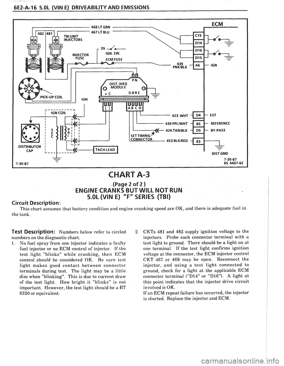
CHART A-3
(Page 2 of 2 )
ENGINE CRANKS BUT WILL NOT RUN
5.OL (VIN E) "F'XSERIES (TBI)
Circuit Description:
This chart assumes that battery condition and engine cranking speed are OK, and there is adequate fuel in
the tank.
Test Description: Numbers below refer to circled 2.
numbers on the diagnostic chart.
1. No fuel spray from one injector indicates a faulty
fuel injector or no ECM control of injector. If the
test light "blinks" while cranking, then
ECM
control should be considered OK. Be sure test
light makes good contact between connector
terminals during test.
The light may be a little
dim when "blinking". This is due to current draw
of the test light. How bright it "blinks" is not
important. However, the test light should be
a BT
8320 or equivalent.
CKTs 481 and 482 supply ignition voltage to the
injectors. Probe each connector terminal with a
test light to ground. There should be a light on at
one terminal.
If the test light confirms ignition
voltage at the connector, the ECM injector control
CKT 467 or 468 may be open. Reconnect the
injector, and using a test light connected to
ground, check for a light at the applicable ECM
connector terminal
("D14" or "D16"). A light at
this point indicates that the injector drive circuit
involved is OK.
If an ECM repeat failure has occurred, the injector
is shorted. Replace the injector and ECM.
Page 512 of 1825
DRIVEABILITY AND EMISSIONS 5.OL (VIN E) CEZ-A-21
@ DISCONNECT FUEL RETURN LlNE
FLEXIBLE HOSE.
ATTACH
5/16 1.D. FLEX HOSE TO
THROTTLE BODY SIDE OF RETURN LINE.
INSERT THE OTHER END IN AN APPROVED
GASOLINE CONTAINER.
r NOTE FUEL PRESSURE WITHIN 2 SECONDS
@ APPLY 12 VOLTS TO FUEL
CHECK FOR RESTRICTED
FUEL RETURN
LlNE FROM
THROTTLE BODY.
CLEAR CODES AND CONFIRM "CLOSED LOOP
" OPERATION AND NO "SERVICE ENGINE SOON" LIGHT.
Page 513 of 1825
OXYGEN ( 0,) SENSOR GROUND
-
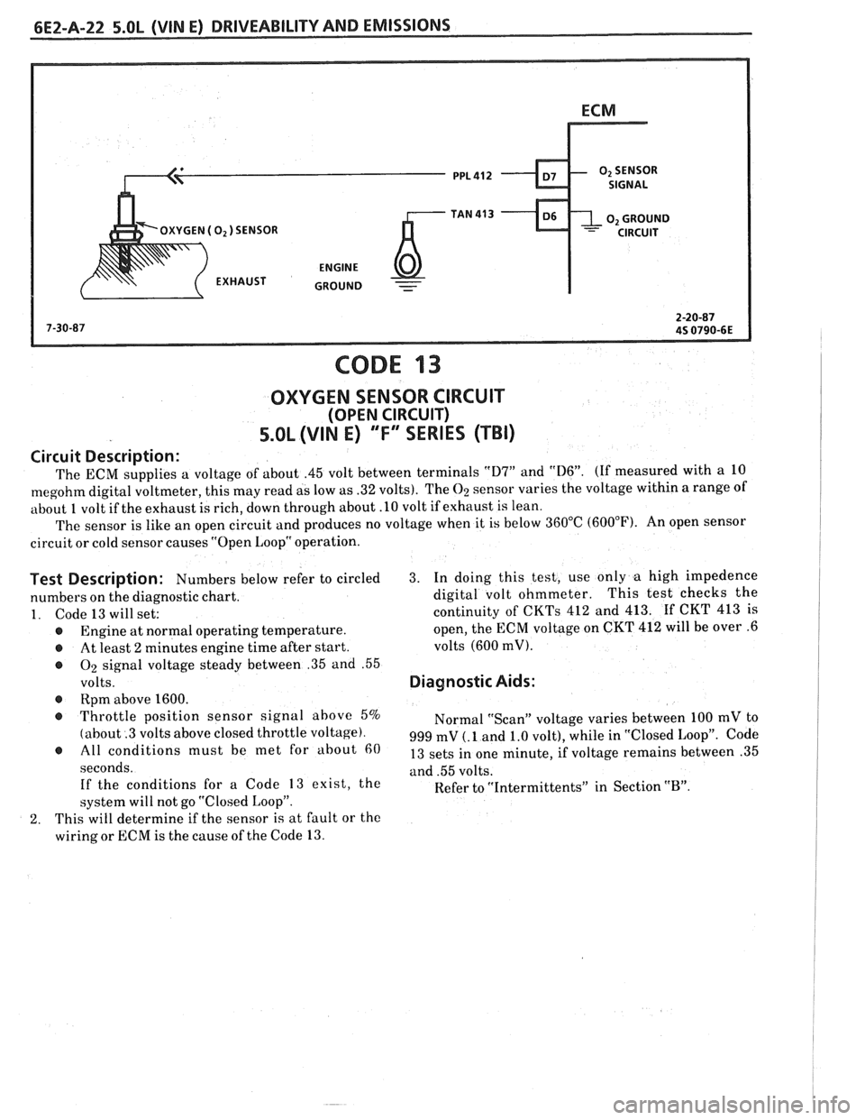
CODE 13
OXYGEN SENSOR CIRCUIT
(OPEN CIRCUIT)
5.OL (VIN E) ""FYERIES (TBI)
Circuit Description:
The ECM supplies a voltage of about .45 volt between terminals "D7" and "D6". (If measured with a 10
megohm digital voltmeter, this may read as low as .32 volts). The 02 sensor varies the voltage within a range of
about
1 volt if the exhaust is rich, down through about .10 volt if exhaust is lean.
The sensor is like an open circuit and produces no voltage when it is below 360°C (600°F). An open sensor
circuit or cold sensor causes "Open Loop" operation.
Test Description: Numbers below refer to circled 3. In doing this test, use only a high impedence
numbers on the diagnostic chart. digital
volt ohmmeter. This test
checks the
1. Code 13 will set: continuity of CKTs 412 and 413. If CKT 413 is
@ Engine at normal operating temperature. open,
the ECM voltage on CKT 412 will be over .6
@ At least 2 minutes engine time after start. volts (600 mV).
@ On signal
voltage steady between .35 and .55
volts. Diagnostic Aids:
@ Rpm above 1600.
@ Throttle position sensor signal above 5%
Normal "Scan" voltage varies between 100 mV to
(about .3 volts above closed throttle voltage). 999 mV (. 1 and 1.0 volt), while in "Closed Loop". Code @ must be met for about 13 sets in one minute, if voltage remains between .35
seconds. and .55 volts.
If the conditions for a Code
13 exist, the
Refer to "Intermittents" in Section "B". system will not go "Closed Loop".
2. This will determine if the sensor is at fault or the
wiring or ECM is the cause of the Code
13.
Page 514 of 1825
DRIVEABILITY AND EMISSIONS 5.OL (VIN E) 6EZ-A-23
"SCAN" SHOULD DISPLAY 0, VOLTAGE BELOW -2
VOLTS (200 mV) WITH ENGINE RUNNING.
CHECK VOLTAGE OF CKT 412 (ECM SIDE) AT
O2
Page 515 of 1825
bE2-A-24 S.OL (VIN E) DRIVEABILITY AND EMlSSlONS
SENSOR GND
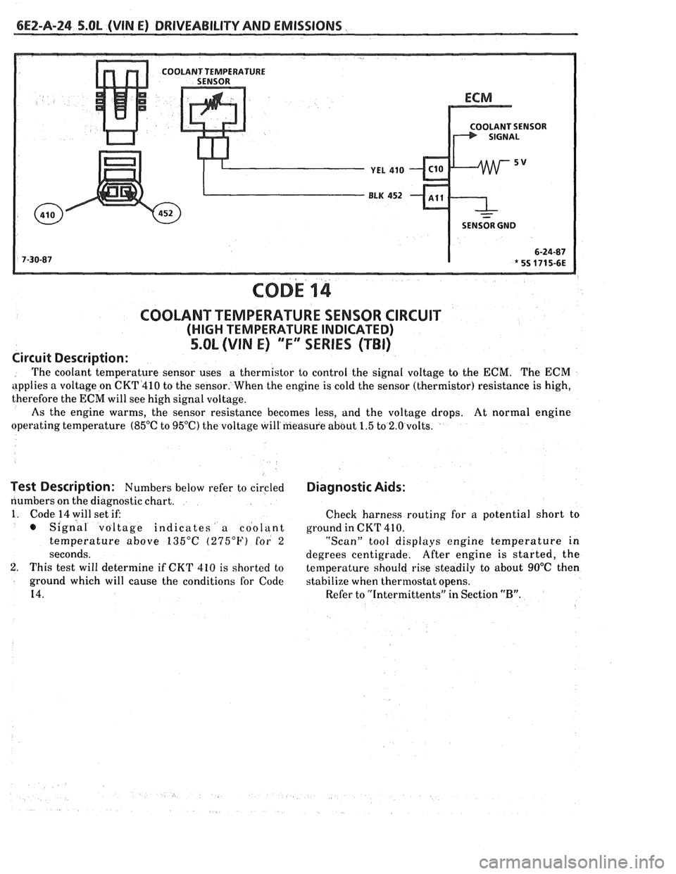
COD^ 14
COOLANT TEMPERATURE SENSOR CIRCUIT
(HIGH TEMPERATURE INDICATED)
5.OL (VIN E) "F"" SERIES (TBI)
Circuit Description:
The coolant temperature sensor uses a
thermistor to control the signal voltage to the ECM. The ECM
applies a voltage on CKT4410 to the sensor. When the engine is cold the sensor (thermistor) resistance is high,
therefore the
ECM will see high signal voltage.
As the engine warms, the sensor resistance becomes less, and the voltage drops. At normal engine
operating temperature
(85°C to 95OC) the voltage will'measure about 1.5 to 2.0 volts.
Test Description: Numbers below refer to circled
numbers on the diagnostic chart.
1. Code 14 will set if:
s Signal voltage indicates a coolant
temperature above
135°C (275°F) for 2
seconds.
2. This test will determine if CKT 410 is shorted to
ground which will cause the conditions for Code
14.
Diagnostic Aids:
Check harness routing for a potential short to
ground in CKT
41 0.
"Scan" tool displays engine temperature in
degrees centigrade. After
engine is started, the
temperature should rise steadily to about
90°C then
stabilize when thermostat opens.
Refer to "Intermittents" in Section
"B".
Page 517 of 1825
6EZ-A-26 5.8L (VIN E) DRIVEABILITY AND EMISSIONS
OLANT SENSOR
SENSOR GND
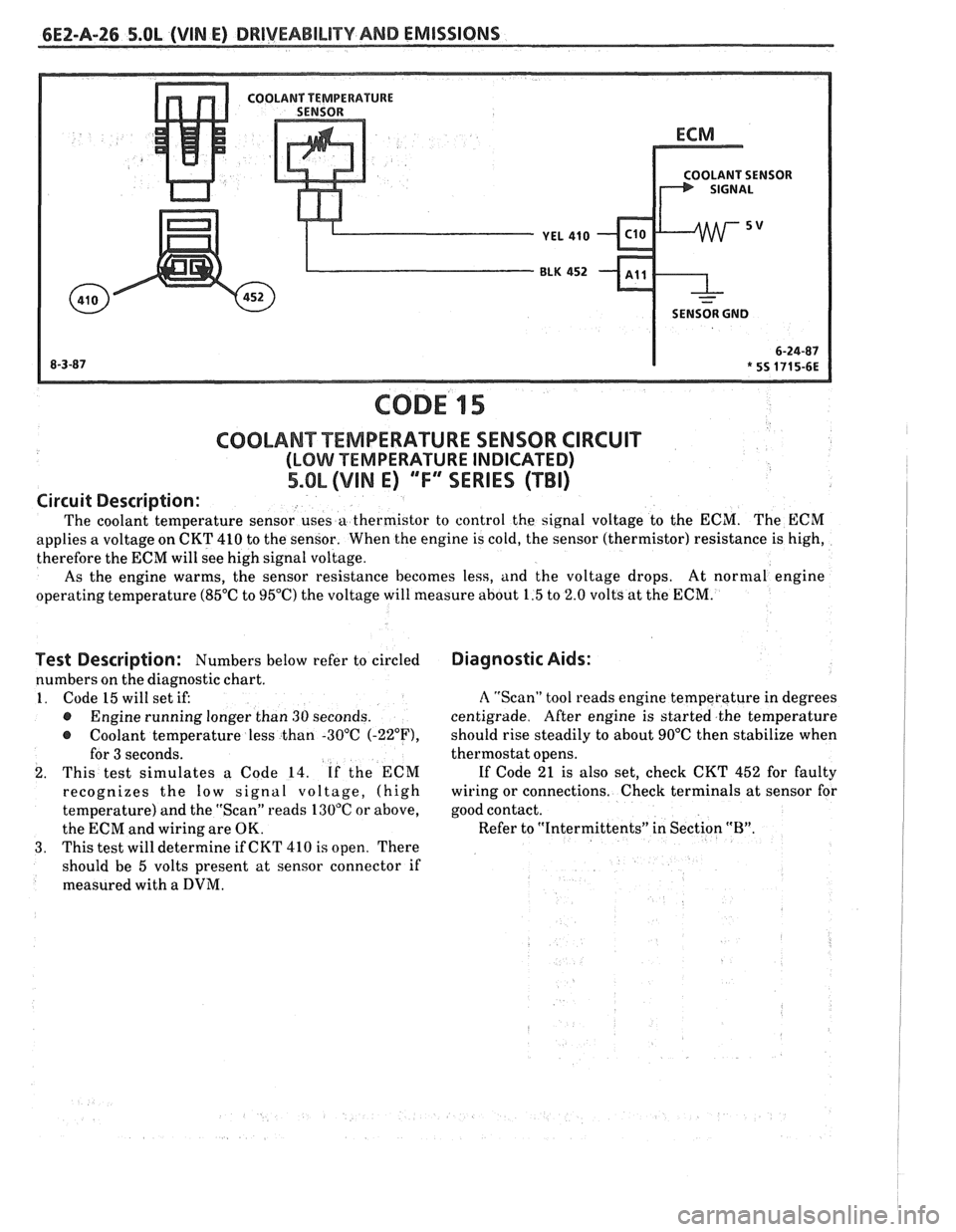
CODE 15
Test Description: Numbers below refer to circled
numbers on the diagnostic chart.
1. Code 15 will set if:
@ Engine running longer than 30 seconds.
@ Coolant temperature less than -30°C (-22"F),
for 3 seconds.
2. This test simulates a Code 14. If the ECM
recognizes the
low signal voltage, (high
temperature) and the "Scan" reads 130°C or above,
the ECM and wiring are OK.
3. This test will determine if CKT 410 is open. There
should be 5 volts present at sensor connector if
measured with a
DVM.
COOLANT TEMPERATURE SENSOR CIRCUIT
(LOMI TEMPERATURE INDICATED)
5.OL (VIM E) ""FYERIES (TBI)
Diagnostic Aids:
Circuit
Description:
The coolant temperature sensor uses a thermistor to control the signal voltage to the ECM. The ECM
applies a voltage on CKT 410 to the sensor. When the engine is cold, the sensor (thermistor) resistance is high,
therefore the ECM will see high signal voltage.
As the engine warms, the sensor resistance becomes less, and the voltage drops. At
normal engine
operating temperature (85°C to 95°C) the voltage will measure about 1.5 to 2.0 volts at the ECM.
A "Scan" tool reads engine temperature in degrees
centigrade. After engine is started the temperature
should rise steadily to about 90°C then stabilize when
thermostat opens.
If Code 21 is also set, check CKT 452 for faulty
wiring or connections. Check terminals at sensor for
good contact.
Refer to "Intermittents" in Section
"B".
~
Page 521 of 1825
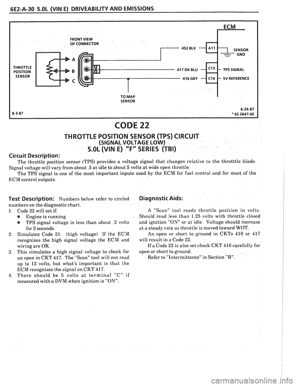
FRONT VIEW OF CONNECTOR
5V REFERENCE
SENSOR
CODE 22
THROTTLE POSITION SENSOR (TPS) CIRCUIT
(SIGNAL VOLTAGE LOW)
5.OL (VIN E) "'F3ERIES (TBI)
Circuit Description:
The throttle position sensor (TPS) provides a voltage signal that changes relative to the throtttle blade.
Signal voltage will vary from about
.5 at idle to about 5 volts at wide open throttle.
The TPS signal is one of the most important inputs used
by the ECM for fuel control and for most of the
ECM control outputs.
Test Description: Numbers below refer to circled
numbers on the diagnostic chart.
1. Code 22 will set if:
Engine is running
r TPS signal voltage is less than about .2 volts
for
2 seconds.
2. Simulates Code 21: (high voltage) If the ECM
recognizes the high signal voltage the ECM and
wiring are OK.
3. This simulates a high signal voltage to check for
an open in CKT 417. The "Scan" tool will not read
up to 12 volts, but what's important is that the
ECM recognizes the signal on CKT 417.
4. There should be
5 volts at terminal "C" if
measured with a DVM when ignition is "ON".
Diagnostic Aids:
A "Scan" tool reads throttle position in volts.
Should read less than 1.25 volts with throttle closed
and ignition "ON" or at idle. Voltage should increase
at a steady rate as throttle is moved toward WOT.
An open
or short to ground in CKTs 416 or 417
will result in a Code 22.
If a Code 22 is also set check CKT 416 carefully for
open or short to ground.
Refer to "Intermittents" in Section
"B".
Page 523 of 1825
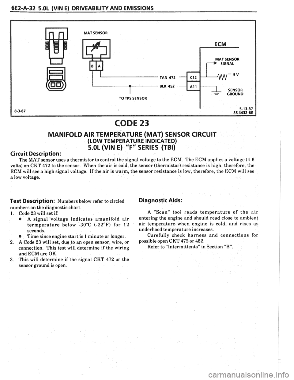
6E2-A-32 S.OL (VIN E) DRIVEABILITY AND EMISSIONS
MAT SENSOR
MAT SENSOR
TAN
472 C12
BLK 452 - ~11
- GROUND
TO TPS SENSOR
CODE 23
MANIFOLD AIR TEMPERATURE (MAT) SENSOR CIRCUIT
(LOW TEMPERATURE INDICATED)
5.OL (VIN E) "F" SERIES (TBI)
Circuit Description:
The MAT sensor uses a thermistor to control the signal voltage to the ECM. The ECM applies a voltage (4-6
volts) on CKT 472 to the sensor. When the air is cold, the sensor (thermistor) resistance is high, therefore, the
ECM will see a high signal voltage. If the air is warm, the sensor resistance is low, therefore, the
E:CM will see
a low voltage.
i
Test Description: Numbers below refer to circled
numbers on the diagnostic chart.
1. Code 23 will set if:
@ A signal voltage indicates amanifold air
termperature below -30°C
(-22°F) for 12
seconds.
@ Time since engine start is 1 minute or longer.
2. A Code 23 will set, due to an open sensor, wire, or
connection. This test will determine if the wiring
and ECM are OK.
3. This will determine if the signal CKT 472 or the
sensor ground is open.
Diagnostic Aids:
A "Scan" tool reads temperature of the air
entering the engine and should read close to ambient
air temperature when engine is cold, and rises as
underhood temperature increases.
Carefully check harness and connections for
possible open CKT
472 or 452.
Refer to "Intermittents" in Section "B".