1988 PONTIAC FIERO check engine
[x] Cancel search: check enginePage 556 of 1825
DRIVEABILITY AND EMISSIONS 5.OL (VIN El 6EZ-C1-1
SECTION Cl
ELECTWONllC CONTROL MODULE (ECM) AND SENSORS
CONTENTS
GENERAL DESCRIPTION . . . . . . . . . . . . . . . C1-1 Coolant Temperature Sensor . . . . . . . . C1-5
ELECTRONIC CONTROL MODULE (ECM) . . C1-1 MAT Sensor. . . . . . . . . . . .. . . ... . . . . $1 -5
PROM ........................... C1-1 MAP Sensor. . . . . . . . . . . . . . . . . . . . . . C1 -6
CALPAK.........,................ C1-2 Oxygen (02) Sensor. . . . . . ... . . . a C1-6
ECM FUNCTION . . . , . . . . . . . . . . . . . . . . C1-2 Throttle Position Sensor (TPS) . . . . . . . . C1-6
INFORMATION SENSORS . . . . . . . . . . . . . C1-2 Vehicle Speed Sensor (VSS) . . . . . . . . . C1-6
Engine Coolant Temperature Sensor . . C1-2 PIN Switch. . . . . . . . . . . . . . . . . . . . . . . C1-6
MAP Sensor. . . . . . . . . . . . . . . . . . . . . . C1-2 (PSPS) . . . . . ... .. . . . ... . . .. .. . . . C1-6
MAT Sensor. . . . . . . . . . . . . . . . . . . . . . C1-3 AJC Request Signal . . . . . . . . . . . . . . . . C1-6
Oxygen (Oz) Sensor. . . . . . . . . .. . . . . . C1-3 Distributor Reference Signal . . . . . . . . . C1-6
Throttle Posit~on Sensor (TPS) . . . . . . . . C1-3 Knock Signal . . . . . . . . . . . . . . . . . . . C1-6
Knock Sensor . . . . . . . . . . . . . . . . . . . . C1-4 ON-CAR SERVICE . . . . . . . . . . . . . . . . . . . . . C1-6
Park Neutral Switch (Auto Only) . . . . . . C1-4 ELECTRONIC CONTROL MODULE . . . . . . . 61-6
Crank Signal . . . . . . , . . . . . . . . . . . . . . C1-4 PROM ........................... C1-7
A/C "On" Signal . . . , . . . . . . . . . . . . . . C1-4 Functional Check . . . . . . . . . . . . . . . . . C1-8
Vehicle Speed Sensor (VSS) . . . . . . . . . C1-4 CALPAK...................,...... C1-8
Distributor Reference Signal . . . . . . . . . C1-4 COOLANTSENSOR .. . . . . . . . , . . . . . . . . . C1-9
(PSPS) . . . . . . . . . . . . . . . . . . . . . . . . . C1-4 MAPSENSOR ..... ........ ... . .. . .* C1-9
DIAGNOSIS . . . . . . . . . . . . . . . . . . . . . . . . . C1-5 OXYGEN (02) SENSOR . . . . . . . . . a . . a . . C1-9
ECM ............................. C1-5 THROTTLE POSITION SENSOR (TPS) . . . . . C1-10
PROM ........................... C1-5 PARKINEUTRALSWITCH . . . . . . . . . . . . . . C1-10
ECM INPUTS.. . . . . . . . . . . . . . . . , . . . . . C1-5 PARTS
INFORMATION . . . . . . . . . . . . . . . . . C1-10
GENERAL DESCRIPTION
ELECTRONIC CONTROL MODULE (ECM)
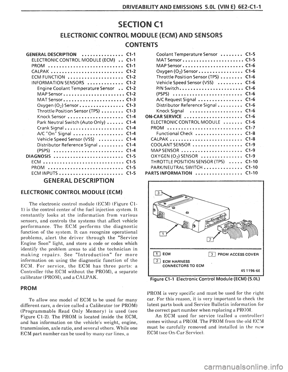
The electronic control module (KCMI (Figure C1-
1) is the control center of the fuel ir!jection system. It
constantly looks at the information from various
sensors, and controls the systems that affect vehicle
performance. The ECM performs the diagnostic
function of the system. It can recognize operational
problems, alert the driver through the "Service
Engine Soon" light, and store a code or codes which
identify the problem areas to aid the technician in
making repairs. See "Introduction" for more
information on using the diagnostic function of the
ECM. For service, the ECM has three parts:
a
Controller (the ECM without the PROM), a separate
calibrator (PROM), and a
CALPAK.
To allow one model of ECM to be used for many
different cars, a device called a Calibrator (or PROM)
(Programmable Read Only Memory) is used (see
Figure
C1-2). The PROM is located inside the ECM,
ancl has information on the vehicle's weight, engine,
transmission, axle ratio, and several others. While one
ECM part number can be used by many car lines, a
ECM PROM ACCESS COVER
1 ECM HARNESS
CONNECTORS TO ECM
45 1196-6E
Figure C1-1 Electronic Control Module (ECM) (5.OL)
PROM is very specific and must be used for the right
car. For this reason, it is very important to checlc the
latest parts book and Service Bulletin information for
the correct part number when replacing
a PROM.
An ECM used for service (called a controller)
comes without a
PROM. The PROM from the old blC>1
must be carefully removed and installctl in the new
EChI (see On-Car Service).
Page 560 of 1825
DRIVEABILITY AND EMISSIONS 5.OL (VIN E) 6EZ-C1-5
DIAGNOSIS
Since the ECM can have a failure which may
effect only one circuit, following the diagnostic
procedures in this section can reliably tell when a
failure has occurred in the ECM. Also,
a Code
55 in
dicates a failure of the ECM.
If a diagnostic chart indicates that the ECM
connections or ECM is the cause of a
problem,and the
ECM is replaced, but does not correct the problem, one
of the following may be the reason:
e
connections. - The diagnostic chart will say "ECM
Connections or ECM". The terminals mav have to be
removed from the connector in order to check them
properly.
@ The ECM or PROM is not correct for the
. - The incorrect ECM or PROM may cause
a malfunction and may or may not set a code.
. - This means that
time the system is
being checked. In this case, refer to the "Symptoms"
portion of the manual and make a careful physical
Solenoids and relays are turned "ON" and "OFF" by
the ECM, using internal electronic switches called
"Drivers".
A shorted solenoid, relay coil, or harness in a
GMP4 computer will not damage the ECM,
but will cause the circuit and controlled
component to be inoperative. When the
circuit fault is not present or has been
repaired, the "Quad-Driver" will again
operate in a normal manner due to it's fault
protected design. If a fault has been repaired
in a circuit controlled
by a "Quad-Driver", the
original
ECM should be reinstalled and the
circuit checked for proper operation.
ECM
replacement will not be necessary if the
repaired circuit or component now operates
correctly.
534636 or BT8405 testers or equivalent provide a
fast, accurate means of checking for a shorted coil or a
short to battery voltage.
e , - Although the
PROM rarely
fails,it operates as part of the ECM.
Therefore, it could be the cause of the problem.
Substitute a known good PROM.
o . - After the
ECM is replaced, the system should be rechecked for
proper operation. If the diagnostic chart again
indicates the ECM is the problem, substitute a known
good ECM. Although this is a rare condition, it could
happen. The
components or circuits and the codes or
charts, related to them are:
@ Code 55 indicates a failure of the ECM.
@ PROM - Code 51.
@ Coolant Temperature Sensor - CHARTS 14 -
15.
@ MAP sensor - CHART 33 or 34. To check the
sensor with no code set, use CHART
C-1D.
e TPS - CHARTS 21 or 22.
e PIN switch - CHART C-1A
@ Crank Signal - CHART C-1B
@ O2 Sensor - CHARTS 13,44,45.
@ VSS - CHART 24 and in TCC System.
e Distributor - CHART 42 and in EST system.
@ Distributor - Chart and in the EST system.
ECM
A faulty ECM will be determined in the diagnostic
charts, or by a Code 55.
PROM
An incorrect or faulty PROM, which is part of the
ECM, may set a Code 51.
ECM INPUTS
All of the sensors and input switches can be
diagnosed by the use of a "Scan" tool. Following is
a
short description of how the sensors and switches can
be diagnosed by the use of "a Scan" tool. The
"Scan"
tool can also by used to compare the values for a
normal running engine with the engine you're
diagnosing.
Coolant Temperature Sensor
A "Scan" tool displays engine temp. in degrees
centigrade. After the engine is started, the
temperature should rise steadily to about
90°C, then
stabilize when thermostat opens.
A fault in the
coolant sensor circuit should set a Code 14 or 15. The
code charts also contain a chart to check for sensor
resistance values relative to temperature.
MAT Sensor
A "Scan" tool displays temperature of the air
entering the engine and should read close ambient air
temperature, when engine is cold, and rise
as
underhood temperature increases. If the engine has
not been run for several hours (overnight), the MAT
sensor temperature and coolant temperature should
read close to each other.
Page 561 of 1825
6EZ-C1-6 5.OL (VIN E) DRIVEABILITY AND EMISSIONS
A failure in the MAT sensor circuit should set a Code
23 or 25. The code charts also contain
a chart to check
for sensor resistance values relative to temperature.
MAP Sensor
A "ScanJ' tool reads manifold pressure and will
display either volts or
kPa of pressure.
Key "ONJ', engine stopped, (no vacuum), MAP will
read high voltage or pressure, while at idle
(highvacuum), MAP will read low voltage or pressure.
Likewise, on accel., MAP will read high and on decel.,
will read low.
A failure in the MAP sensor, or circuit, should
result in a Code 33 or 34.
Oxygen (02) Sensor
The "Scan" tool has several positions that will
indicate the state of the exhaust gases,
02 voltage,
integrator, and block learn. See "Scan" tool position
information in the Introduction of Section
"6E".
A problem in the O2 sensor circuit should set a
Code 13 (open circuit), Code
44 (lean 02 indication),
Code
45 (rich 02 indication). Refer to the applicable
chart, if any of these codes were stored in memory.
Throttle Position Sensor (TPS)
A "Scan" tool displays throttle position in volts.
The
5.OL should read under 1.25 volts, with throttle
closed and ignition on, or at idle. Voltage should
increase at a steady rate as throttle is moved toward
WOT. The ECM has the ability to Auto-Zero the TPS
voltage, if it is below about 1.25 volts. This means
that any voltage less than 1.25 volts volts will be
determined by the ECM to be
0% throttle. Some
"Scan" tools have the ability to read the percentage of
throttle angle and should read
0%, when the throttle
is closed.
A failure in the TPS circuit or TPS, should
set a Code 21 or 22.
Vehicle Speed Sensor (VSS)
A "Scan" tool reading should closely match with
speedometer reading, with drive wheels turning. A
failure in the VSS circuit should set a Code
24.
PIN Switch
A "Scan" tool should read "ON", when in park or
neutral and "OFF", when in drive. This reading may
vary with different makes of tools. Refer to CHART C-
IA for
PIN switch diagnosis.
Power steering Pressure Switch (POPS)
A Scan" tool should read "OFF" normally, and
"ON" with high pressure. This reading may vary with
different makes of tools. Refer to CHART
C-1E for
PSPS diagnosis.
NC Request Signal
If the low pressure switch is closed and AIC is
"ON", the "Scan" tool should indicate
A/C "ON".
Distributor Reference Signal
A "Scan" tool will read this signal and is displayed
in rpm. See Section
"C4", for more information on the
Ignition System
.
Knock Signal
A "Scan" tool will indicate when the ESC module
signals the ECM that knock is present. See Section
"C5" for further information on the ESC System.
ON-CAR SERVICE
ELECTRONIC CONTROL MODULE (ECM)
Service of the ECM should normally consist of
either replacement of the ECM or a PROM change.
If the diagnostic procedures call for the ECM to be
replaced, the engine calibrator (PROM) and ECM
should be checked first to see if they are the correct
parts. If they are, remove the PROM from the faulty
ECM and install it in the new service ECM. THE
SERVICE ECM
WILL NOT CONTAIN A PROM.
Trouble Code "51" indicates the PROM is installed
improperly or has malfunctioned. When Code "51" is
obtained, check the PROM installation for bent pins or
pins not fully seated in the socket. If the PROM is
installed correctly and Code
"51" still shows, replace
the PROM.
Important
When replacing the production ECM with a
service ECM (controller), it is important to
transfer the Broadcast code and production ECM
number to the service ECM label. Please do not
record on ECM cover. This will allow positive
identification of ECM parts throughout the service
life of the vehicle.
Page 563 of 1825
6E2-C1-8 5.OL (VIM E) DRIVEABILITY AND EMISSIONS
NOTCH IN PROM REFERENCED
TO SMALLER NOTCH IN
CARRIER AND THE PIN
#I END
REFERENCE END
PROM
PROM CARRIER *4S 0465-6E
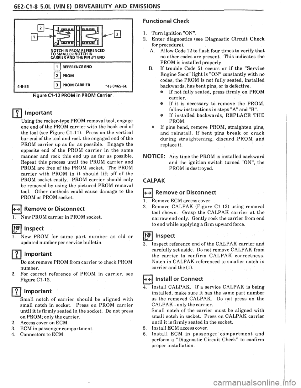
Figure 61-12 PROM in PROM Carrier
lmportant
Using the rocker-type PROM removal tool, engage
one end of the PROM carrier with the hook end of
the tool (see Figure
C1-11). Press on the vertical
bar end of the tool and rock the engaged end of the
PROM carrier up as far as possible. Engage the
opposite end of the PROM carrier in the same
manner and rock this end up as far as possible.
Repeat this process until the PROM carrier and
PROM are free of the PROM socket. The PROM
carrier with PROM in it should lift off of the
PROM socket easily. PROM carrier should only
be removed by using the pictured PROM removal
tool. Other methods could cause damage to the
PROM or PROM socket.
Remove or Disconnect
1. New PROM carrier in PROM socket
Inspect
1. New
PROM for same part number as old or
updated number per service bulletin.
Important
Do not remove PROM from carrier to check PROM
number.
2. For correct
reference of PROM in carrier, see
Figure
C1-12.
important
Small notch of carrier should be aligned with
small notch in socket. Press on
PROM carrier
until it is firmly seated in the socket. Do not press
on PROM; only the carrier.
2. Access cover on ECM.
3. ECM in passenger compartment.
4. Connectors to ECM.
Functional Check
1. Turn ignition "ON".
2. Enter diagnostics (see Diagnostic Circuit Check
for procedure).
A. Allow Code 12 to flash four times to verify that
no other codes are present. This indicates the
PROM is installed properly.
B. If trouble Code 51 occurs or if the "Service
Engine Soon" light is "ON" constantly with no
codes, the PROM is not fully seated, installed
backwards, has bent pins, or is defective.
@ If not fully seated, press firmly on PROM
carrier.
If it is necessary to remove the PROM,
follow instructions in steps "A" and
"B".
@ If installed backwards, REPLACE THE
PROM.
@ If pins bend, remove PROM, straighten pins,
and reinstall. If bent pins break or crack
during straightening, discard PROM and
replace it.
NOTICE: Any time the PROM is installed backward
and the ignition switch turned "ON", the
PROM is destroyed.
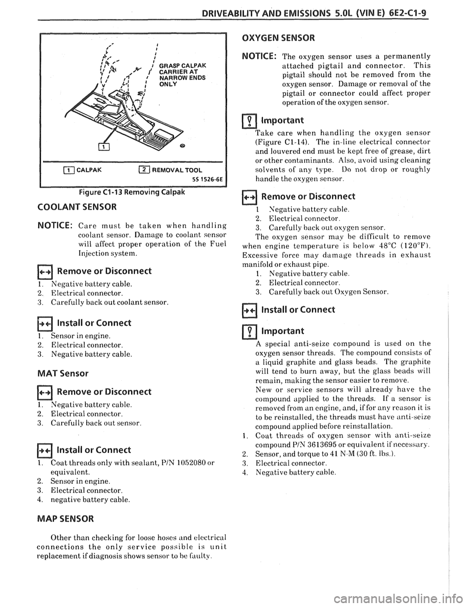
CALPAK
n Remove or Disconnect
1. Remove ECM access cover.
2. Remove
CALPAK (Figure
C1-13) using removal
tool shown. Grasp the CALPAK carrier at the
narrow end only. Gently rock the carrier from end
to end while applying a firm upward force.
Inspect
3. Inspect reference end of the CALPAK carrier and
carefully set aside. Do not remove CALPAK from
the carrier to confirm CALPAK correctness.
Notch in CALPAK referenced to smaller notch in
carrier and the
(1).
a Install or Connect
4. Install CALPAK. If a service CALPAK is being
installed, make sure it has the same part number
as the removed CALPAK. Do
not press on the
CALPAK
- only the carrier.
Small notch of the carrier must be aligned with
small notch in socket. Press on CALPAK carrier
until it is firmly seated in the socket.
5. Install ECM access cover.
6. Install ECM in passenger compartment and
perform a "Diagnostic Circuit Check" to confirm
proper installation.
Page 564 of 1825
DRIVEABILITY AND EMISSIONS 5.OL (VIN E) 6EZ-C1-9
Figure C1-13 Removing Calpak
COOLANT SENSOR
NOTICE: Care must be taken when handling
coolant sensor. Damage to coolant sensor
will affect proper operation of the Fuel
Illjection system.
Remove or Disconnect
1. Negative battery cable.
2. Electrical connector.
3. Carefully back out coolant sensor.
lnstall or Connect
1. Sensor in engine.
2. Electrical connector.
3. Negative battery cable.
MAT Sensor
Remove or Disconnect
I. Negative battery cable.
2. Electrical connector.
3. Carefully back out sensor.
a Install or Connect
I. Coat threads only with sealant, PIN 1052080 or
equivalent.
2. Sensor in engine.
3. Electrical connector.
4, negative battery cable.
OXYGEN SENSOR
NOTICE:
The oxygen sensor uses a permanently
attached pigtail and connector. This
pigtail should not be removed from the
oxygen sensor. Damage or removal of the
pigtail or connector could affect proper
operation of the oxygen sensor.
rn Important
Take care when handling the oxygen sensor - - -
(Figure (21-14). The in-line electrical connector
and louvered end must be kept free of grease, dirt
or other contaminants. Also, avoid using cleaning
solvents of any tvpe.
Do not drop or roughly
handle the oxygen sensor.
a Remove or Disconnect
1 Negative battery cable.
2. Electrical connector.
3. Carefully back out oxygen sensor.
The oxygen sensor may be dit'ficult to remove
when engine temperature is below
48°C (120°F).
Excessive force may damage threads in exhaust
manifold or eshaust pipe.
1. Negative battery cable.
2. Electrical connector.
3. Carefully back out Oxygen Sensor.
lnstall or Connect
rn Important
A s~ecial anti-seize compound is used on the
oxygen sensor threads. The compound consists of
a liquid graphite and glass beads. The graphite
will tend to burn away, but the glass beads will
remain, making the sensor easier to remove.
New or service sensors will already have the
compound applied to the threads. If a sensor is
removed from an engine, and, if for any
reason it is
to be reinstalled, the threads must have
anti-sei~e
compound applied before reinstallation.
1. Coat threads of oxygen sensor with anti-seize
compound
PIN 3613695 or equivalent if neceshary.
2. Sensor, and torque to 41 N,M (30 ft. Ibs.).
3. Electrical connector.
4. Negative battery cable.
MAP SENSOR
Other than checking for loose hoses and electrical
connections the only service possible
is unit
replacement if diagnosis shows sensor to
be faulty.
Page 567 of 1825
6E2-C1-12 DRlVEABlLllV AND EMISSIONS - 5.OL (VIN E)
434 ORNIBLK
450 BLWHT
ENGINE GROUND
CHART C-lA
PARWNEUTRAL SWIKC DIAGNOSIS
(AUTO TRANSMISSION ONLY)
5.0L (VIN E) ""FYmSERIES (TBI)
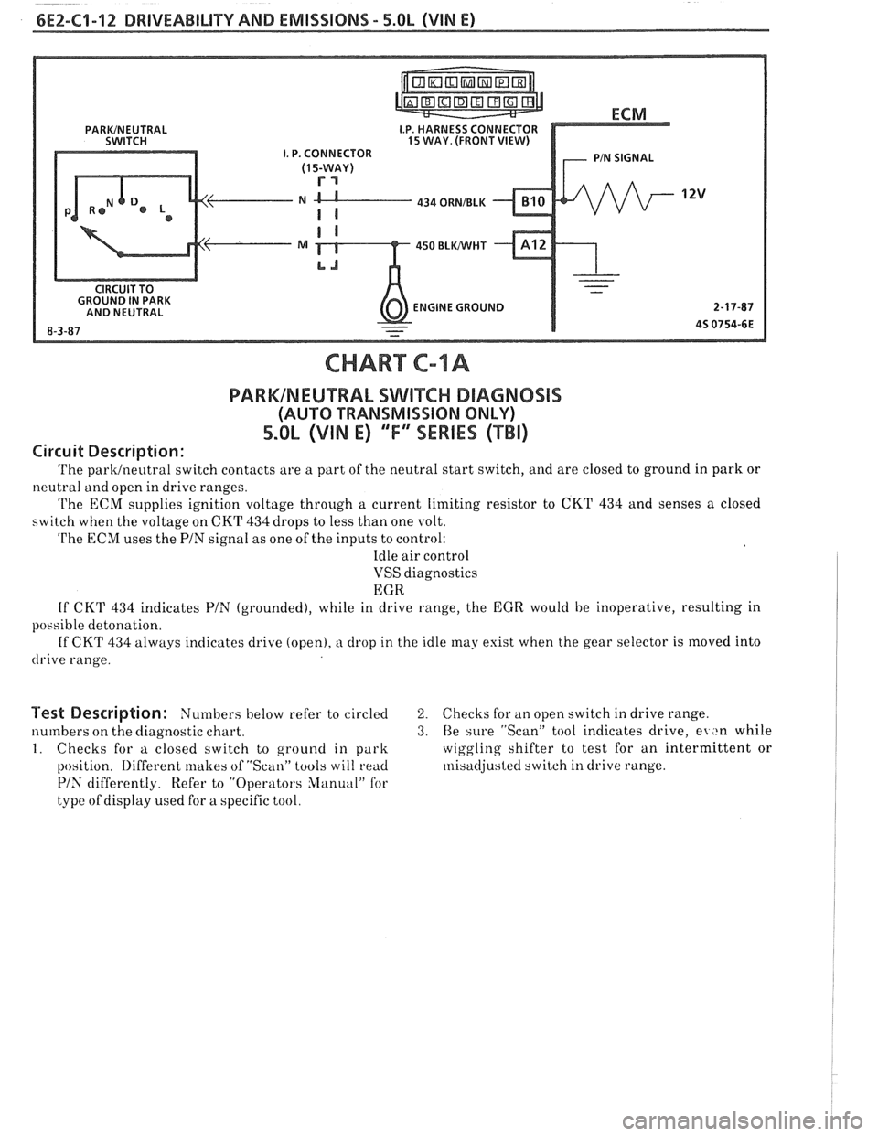
Circuit Description:
The parklneutral switch contacts are a part of the neutral start switch, and are closed to ground in park or
neutral and open in drive ranges.
The ECM supplies ignition voltage through a current limiting resistor to CKT 434 and senses a closed
switch when the voltage on CKT
434 drops to less than one volt.
The ECM uses the PIN signal as one of the inputs to control:
Idle air control
VSS diagnostics
EGR
If CKT
434 indicates PIN (grounded), while in drive range, the EGR would be inoperative, resulting in
possible detonation.
If CKT
434 always indicates drive (open), a drop in the idle may exist when the gear selector is moved into
drive range.
Test Description: Numbers below refer to circled 2. Checks for an open switch in drive range.
numbers on the diagnostic chart.
3. Be sure "Scan" tool indicates drive, el ,tn while
I. Checks for a closed switch to ground in park wiggling
shifter to test for an intermittent or
position.
Iliffercnt lrlakes of "Scan" tools will rend ~nisadjusted switch in drive range.
PIS differently. Refer to "Operators Slanuul" for
type of display used for a specific tool.
Page 569 of 1825

6E2-C1-14 DRlVEABlLlTV AND EMISSIONS - 5.OL (VIN E)
806 PPUWHT CRANK SIGNAL
STARTER SOLENOID
('HOT' DURING CRANK)
CHART C-l B
CRANK SIGNAL
5.OL (VIN E) "F" "SERIES (TBI)
Circuit Description:
Crank signal is a 12 volts signal to the ECM during cranking to allow enrichment and cancel diagnostics
until engine is running and 12 volts is no longer on circuit.
Test Description: Numbers below refer to circled 2. Checks to determine if source of blown fuse was a
numbers on the diagnostic chart. faulty
ECM.
1. Checks for normal (cranking) voltage to terminal
"C9" of ECM. Test light should be "ON" during
cranking.
Page 570 of 1825

DRIVEABILITY AND EMISSIONS - 5.0b (VIN E) 6E2-C9-15
RECHECK FUSE.
CLEAR CODES AND CONFIRM "CLOSED LOOP" OPERATION AND NO "SERVICE
ENGINE SOON" LIGHT.