1988 PONTIAC FIERO check engine
[x] Cancel search: check enginePage 609 of 1825
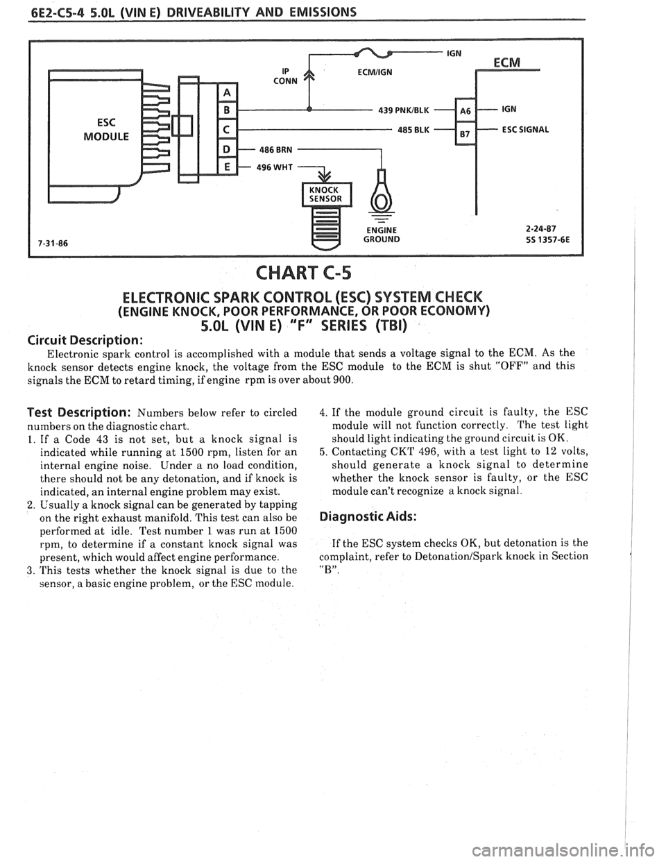
CHART C-5
ELECTRONIC SPARK CONTROL (ESC) SYSTEM CHECK
(ENGINE KNOCK, POOR PERFORMANCE, OR POOR ECONOMV)
5.OL (VIN E) "F" SERIES (TBI)
Circuit Description:
Electronic spark control is accomplished with a module that sends a voltage signal to the ECM. As the
knock sensor detects engine knock, the voltage from the ESC module to the ECM is shut "OFF" and this
signals the ECM to retard timing, if engine rpm is over about 900.
Test Description: Numbers below refer to circled
numbers on the diagnostic chart.
1. If a Code
43 is not set, but a knock signal is
indicated while running at 1500 rpm, listen for an
internal engine noise. Under a no load condition,
there should not be any detonation, and if knock is
indicated, an internal engine problem may exist.
2. Usually a knock signal can be generated by tapping
on the right exhaust manifold. This test can also be
performed at idle. Test number 1 was run at 1500
rpm, to determine if a constant knock signal was
present, which would affect engine performance.
3. This tests whether the knock signal is due to the
sensor, a basic engine problem, or the ESC module.
4. If the module ground circuit is faulty, the ESC
module will not function correctly. The test light
should light indicating the ground circuit is OK.
5. Contacting CKT 496, with a test light to 12 volts,
should generate a knock signal to determine
whether the knock sensor is faulty, or the ESC
module can't recognize a knock signal.
Diagnostic Aids:
If the ESC system checks OK, but detonation is the
complaint, refer to
Detonation1 Spark knock in Section
"B".
Page 610 of 1825
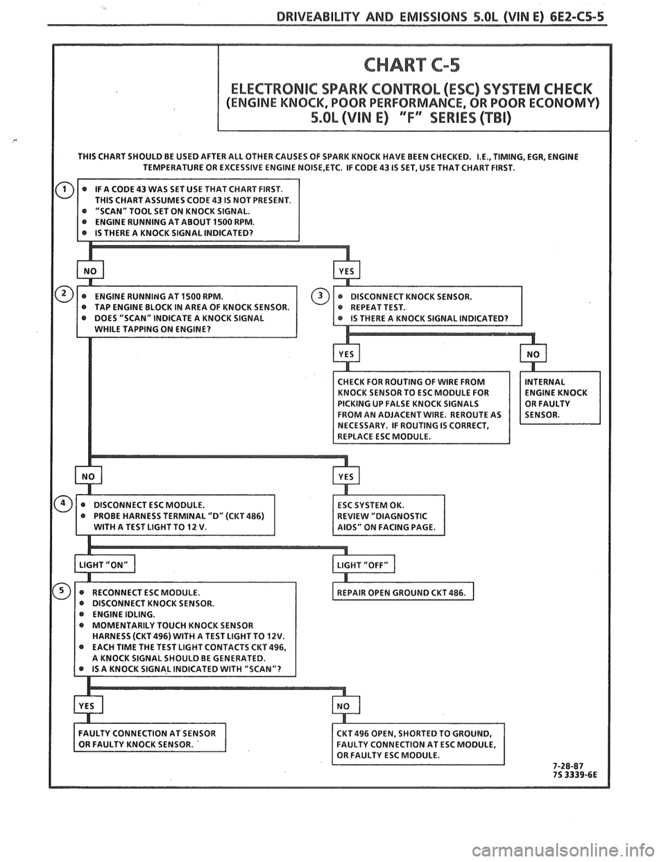
DRIVEABILIW AND EMISSIONS 5.OL (VIN E) 6E2-C5-5
THIS CHART SHOULD BE USED AFTER ALL OTHER CAUSES OF SPARK KNOCK HAVE BEEN CHECKED. I.E., TIMING. EGR, ENGINE
TEMPERATURE OR EXCESSIVE ENGINE NOISE,ETC. IF CODE 43 IS SET, USE THAT CHART FIRST.
@ PROBE HARNESS TERMINAL "D" (CKT 486) EVlEW "DIAGNOSTIC
WITH A TEST LIGHT TO 12 V.
IDS" ON FACING PAGE
Page 612 of 1825
DRIVEABILITY AND EMISSIONS 5.OL (VIN E) 6EZ-C6-1
SECTION C6
AIR INJECTION REACTION (A.I.R.) SYSTEM
CONTENTS
GENERAL DESCRIPTION ............... C6-1
PURPOSE ......................... C6-1
OPERATION ...................... C6-1
AIR CONTROL PEDES VALVE .......... C6-1
RESULTS OF INCORRECT OPERATION .... C6-2
DIAGNOSIS
........................ C6-2
OPERATIONAL CHECKS .............. C6-2
AirPump ...................... C6-2
Hoses and Pipes ................. C6-3
GENERAL DESCRIPTION
PURPOSE
The A.I.R. system helps reduce hydrocarbon (HC),
carbon monoxide (CO), and oxides of nitrogen (NO,)
exhaust emissions. It also heats up the catalytic
converter quickly on engine start-up so conversion of
exhaust gases can occur sooner.
A Dual bed converter is used. It consists of a three
way catalyst (which controls all three emissions) in
series with
a two way catalyst (which controls only HC
and
CO) both are in one housing. A pipe between the
two converters allows air to be injected into the second
(two way) converter to increase its efficiency to further
control
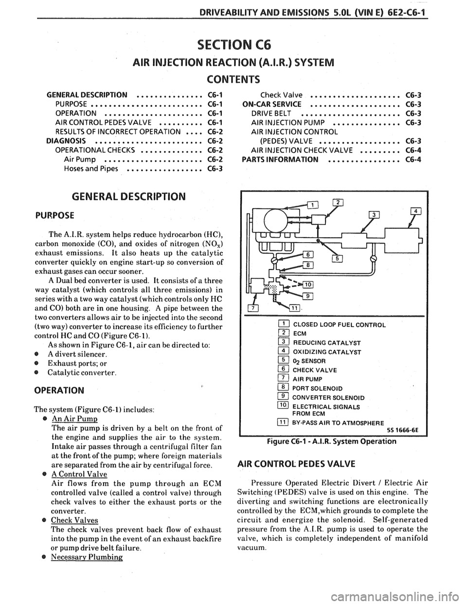
HC and CO (Figure C6-1).
As shown in Figure C6-1, air can be directed to:
@ A divert silencer.
@ Exhaust ports; or
@ Catalytic converter.
OPERATION
The system (Figure C6-1) includes:
@ An Air Pump
The air pump is driven by a belt on the front of
the engine and supplies the air to the system.
Intake air passes through a centrifugal filter fan
at the front of the pump; where foreign materials
are separated from the air
by centrifugal force.
@ A Control Valve
Air flows from the pump through an ECM
controlled valve (called a control valve) through
check valves to either the exhaust ports or the
converter.
@ Check Valves
The check valves prevent back flow of exhaust
into the pump in the event of an exhaust backfire
or pump drive belt failure.
@ Necessary Plumbing
Check Valve .................... C6-3
ON-CAR SERVICE
.................... C6-3
DRIVEBELT ...................... C6-3
AIR INJECTION PUMP ............... C6-3
AIR INJECTION CONTROL
(PEDES) VALVE
.................. C6-3
AIR INJECTION CHECK VALVE ......... C6-4
PARTS INFORMATION
................ C6-4
CLOSED LOOP FUEL CONTROL
ECM
1 REDUCING CATALYST - 1 OXlDlZlNG CATALYST
1 5 SENSOR
CHECK VALVE
1 AIR PUMP
1 PORT SOLENOID
CONVERTER SOLENOID
/ ELECTRICAL SIGNALS
FROM ECM
BY-PASS AIR TO ATMOSPHERE
Figure C6-1 - A.I.R. System Operation
AIR CONTROL PEDES VALVE
Pressure Operated Electric Divert / Electric Air
Switching (PEDES) valve is used on this engine. The
diverting and switching functions are electronically
controlled by the
ECM,which grounds to complete the
circuit and energize the solenoid. Self-generated
pressure from the A.I.R. pump is used to operate the
valve, which is completely independent of manifold
vacuum.
Page 613 of 1825
6EZ-C6-2 5.OL (VIN E) DRIVEABILITY AND EMISSIONS
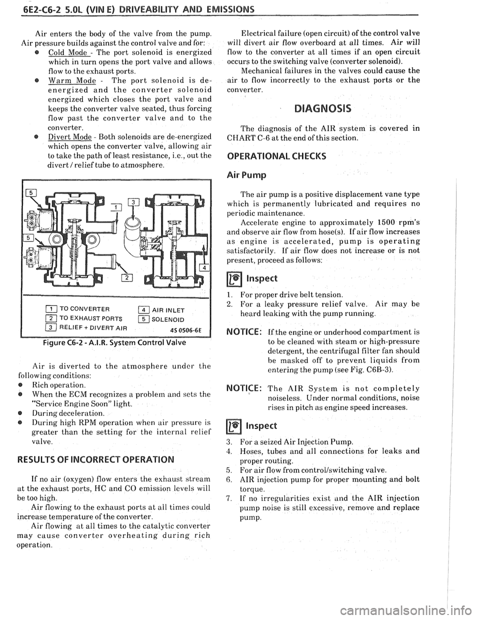
Air enters the body of the valve from the pump.
Air pressure builds against the control valve and for:
@ Cold Mode - The port solenoid is energized
which in turn opens the port valve and allows
flow to the exhaust ports.
@ Warm Mode - The port solenoid is de-
energized and the converter solenoid
energized which closes the port valve and
keeps the converter valve seated, thus forcing
flow past the converter valve and to the
converter.
@ Divert Mode - Both solenoids are de-energized
which opens the converter valve, allowing air
to take the path of least resistance,
i.e., out the
divert
/ relief tube to atmosphere.
TO CONVERTER AIR INLET
1 TO EXHAUST PORTS 1 SOLENOID / RELIEF + DIVERT AIR 45 0506-6E
Figure C6-2 - A.I.R. System Control Valve
Air is diverted to the atmosphere under the
following conditions:
@ Rich operation.
@ When the ECM recognizes a problem and sets the
"Service Engine Soon" light.
@ During deceleration.
During high RPM operation when air pressure is
greater than the setting for the internal relief
valve.
RESULTS OF lNCORRECP OPERATION
If no air (oxygen) flow enters the exhaust stream
at the exhaust ports, HC and CO emission levels will
be too high.
Air flowing to the exhaust ports at all times could
increase temperature of the converter.
Air flowing at all times to the catalytic converter
may cause converter overheating during rich
operation. Electrical failure
(open circuit) of the control valve
will divert air flow overboard at all times. Air will
flow to the converter at all times if an open circuit
occurs to the switching valve (converter solenoid).
Mechanical failures in the valves could cause the
air to flow incorrectly to the exhaust ports or the
converter.
DIAGNOSIS
The diagnosis of the AIR system is covered in
CHART C-6 at the end of this section.
OPERATIONAL CHECKS
Air Pump
The air pump is a positive displacement vane type
which is permanently lubricated and requires no
periodic maintenance.
Accelerate engine to approximately
1500 rpm's
and observe air flow from
hose(s). If air flow increases
as engine is accelerated, pump is operating
satisfactorily. If air flow does not increase or is not
present, proceed as follows:
a Inspect
1. For proper drive belt tension.
2. For a leaky pressure relief valve. Air may be
heard leaking with the pump running.
NOTICE: If the engine or underhood compartment is
to be cleaned with steam or high-pressure
detergent, the centrifugal filter fan should
be masked off to prevent liquids from
entering the pump (see Fig.
C6B-3).
NOTICE: The AIR System is not completely
noiseless. Under normal conditions, noise
rises in pitch as engine speed increases.
inspect
3. For a seized Air Injection Pump.
3. Hoses, tubes and all connections for leaks and
proper routing.
5. For air flow from control/switching valve.
6. AIR injection pump for proper mounting and bolt
torque.
7. If no irregularities exist and the AIR injection
pump noise is still excessive, remove and replace
pump.
Page 617 of 1825
6E2-C6-6 DRIVEABILITY AND EMISSIONS - 5.OL (VIN E)
A.I.W. CONVERTER SOL.
CONNECTORS
429 BLWPNK
CONNECTOR CONNECTOR
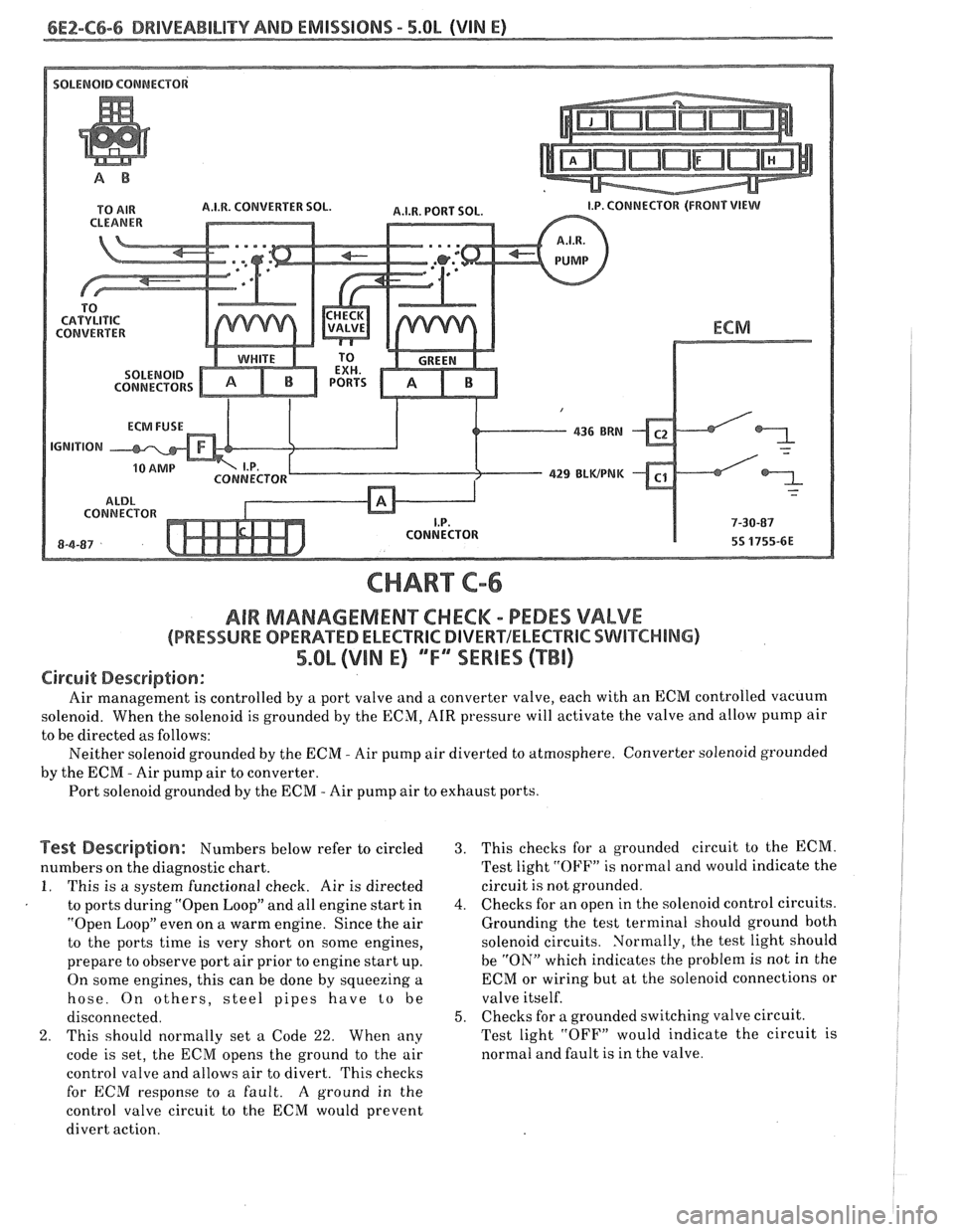
CHART C-6
AIR MAMAGEMENKHECM - PEDES VALVE
(PRESSURE OPERATED ELECTRlC DIVERVELECTRIC SWITCHING)
5.Qb (VIN E) ""FYSERIES (TBI)
Circuit Description:
Air management is controlled by a port valve and a converter valve, each with an ECM controlled vacuum
solenoid. When the solenoid is grounded by the ECM,
AIR pressure will activate the valve and allow pump air
to be directed as follows:
Neither solenoid grounded by the
ECM - Air pump air diverted to atmosphere. Converter solenoid grounded
by the
ECIM - Air pump air to converter.
Port solenoid grounded by the ECM
- Air pump air to exhaust ports.
Test Description: Numbers below refer to circled
numbers on the diagnostic chart.
I. This is a system functional check. Air is directed
to ports during "Open Loop" and all engine start in
"Open Loop" even on a warm engine. Since the air
to the ports time is very short on some engines,
prepare to observe port air prior to engine start up.
On some engines, this can be done by squeezing a
hose. On others, steel pipes have
to be
disconnected.
2. This should normally set a Code 22. When any
code is set, the
ECM opens the ground to the air
control valve and allows air to divert. This checks
for
ECM response to a fault. A ground in the
control valve circuit to the ECM would prevent
divert action.
3. This checks for a grounded circuit to the ECM.
Test light
"OFF" is normal and would indicate the
circuit
is not grounded.
4. Checks for an open in the solenoid control circuits.
Grounding the test terminal should ground both
solenoid circuits. Normally, the test light should
be "ON" which indicates the problem is not in the
ECM or wiring but at the solenoid connections or
valve itself.
5. Checks for a grounded switching valve circuit.
Test light "OFF" would indicate the circuit is
normal and fault is in the valve.
Page 621 of 1825
6E2-C7-2 DRlVEABlLlTV AND EMISSIONS - 5.OL
EGR VALVE AIR BLEED
EXHAUST GAS HOLE
1 INTAKE
AIR SMALL SPRING
1 VACUUM PORT LARGE SPRING
DIAPHRAGM
45 01 13-61
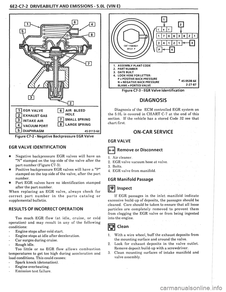
Figure C7-2 - Negative Backpressure EGR Valve
EGR VALVE IDENTIFICATION
@ Negative backpressure EGR valves will have an
"N" stamped on the top side of the valve after the
part number (Figure
C7-3).
@ Positive backpressure EGR valves will have a "P"
stamped on the top side of the valve, after the part
number.
@ Port EGR valves have no identification stamped
after the part number.
When replacing an EGR valve, always check for
correct part number in the parts catalog or
supplemental bulletin.
RESULTS OF INCORRECT OPERATION
Too much EGR flow (at idle, cruise, or cold
operation) and may result in any of the following
conditions:
- Engine stops after cold start.
- Engine stops at idle after deceleration.
- Car surges during cruise.
- Rough idle.
Too little or no EGR flow allows combustion
temperatures to get too high during acceleration and
load conditions. This could causes:
- Spark knock (detonation).
- Engine overheating.
- Emission test failure.
Figure C7-3 - EGR Valve Identification
DIAGNOSIS
Diagnosis of the ECM controlled EGR system on
the
5.OL is covered in CHART C-7 at the end of this
section. If the vehicle has
a stored Code 32 see that
chart first.
ON-CAR SERVICE
ECR VALVE
Remove or Disconnect
1. Air cleaner.
2. EGR valve vacuum hose at valve.
3. Bolts.
4. EGR valve from manifold.
EGR Manifold Passage
inspect
If EGR passages in the inlet manifold indicate
excessive build-up of deposits, the passages should be
cleaned. Care should be taken to ensure that all loose
particles are completely removed to prevent them
from clogging the EGR valve or from being ingested
into the engine.
Clean
1. With a wire wheel, buff the exhaust deposits from
the mounting surface and around the valve.
2. Look for exhaust deposits in the valve outlet.
Remove deposit build-up with a screwdriver.
3. Clean mounting surfaces of intake manifold and
valve assembly.
Page 623 of 1825
6E2-C7-4 DRIVEABILITY AND EMISSIONS - 5.OL (VIN E)
TO EGR VALVE
EGR SOLENOID
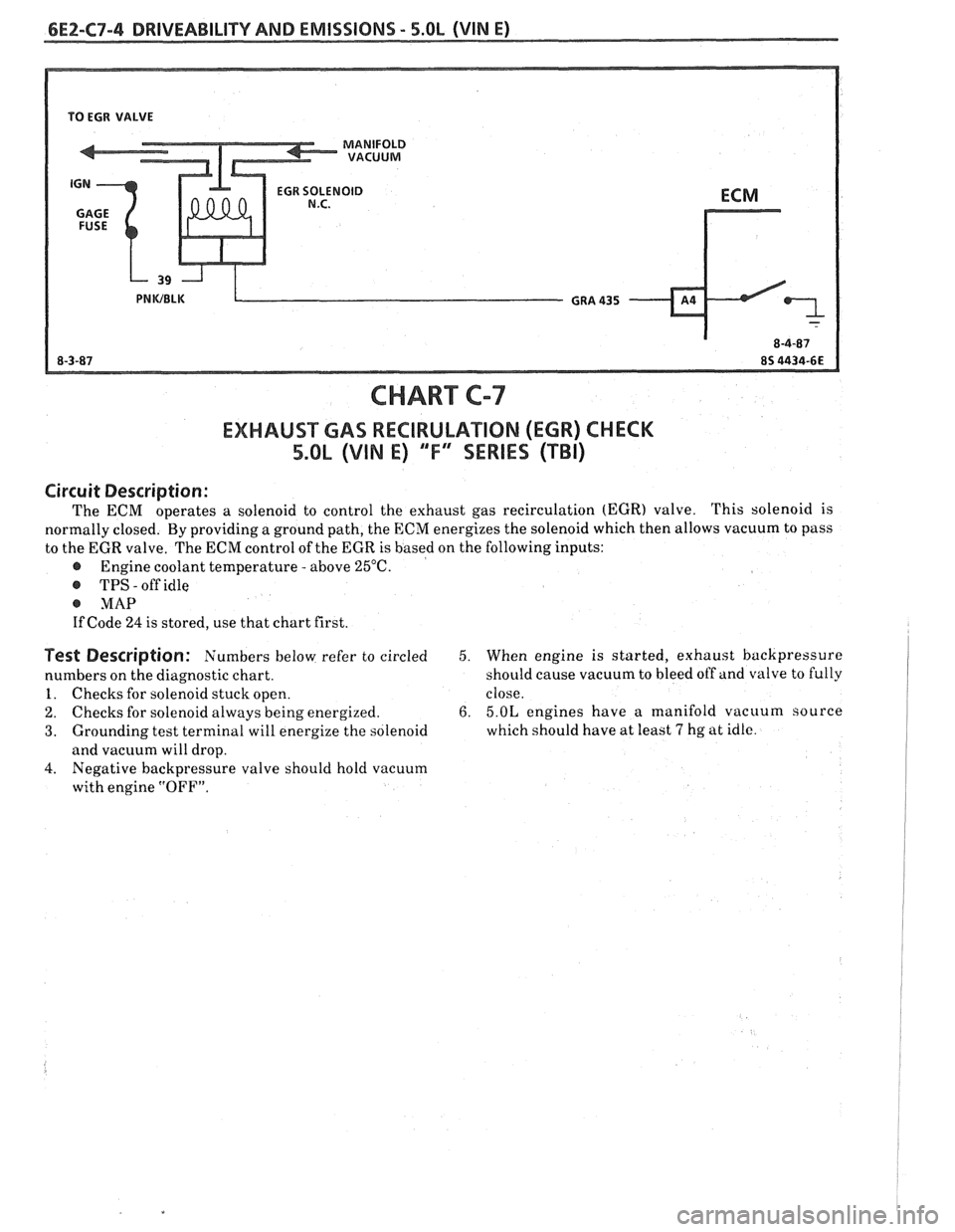
CHART C-7
EXHAUST GAS RECIRULATIOM (EGR) CHECK
5.QL (VIN E) "F" "SERIES (TBI)
Circuit Description :
The ECM operates a solenoid to control the exhaust gas recirculation (EGR) valve. This
solenoid is
normally closed. By providing a ground path, the ECN energizes the solenoid which then allows vacuum to pass
to the EGR valve. The
ECM control of the EGR is based on the following inputs:
@ Engine coolant temperature - above 25°C.
@ TPS - off idle
@ MAP
If Code 24 is stored, use that chart first.
Test Description: Numbers below refer to circled
numbers on the diagnostic chart.
1. Checks for solenoid stuck open.
2. Checks for solenoid always being energized.
3. Grounding test terminal will energize the solenoid
and vacuum will drop.
4. Negative backpressure valve should hold vacuum
with engine
"OFF".
5. When engine is started, exhaust backpressure
should cause vacuum to bleed off and valve to fully
close.
6. 5.OL engines have a manifold vacuum source
which should have at least
7 hg at idle.
Page 627 of 1825
6Ef-C8-2 BRlVEABlLlYV AND EMISSIONS - 5.OL (VIN E) ----
RESULTS OF INCORRECTTCC OPERATION
An engine stall will result if the converter clutch
remains applied at all times.
If the converter clutch does not apply, fuel
economy may be lower than expected.
The transmission converter clutch
(TCC) system
has different operating characteristics than an
automatic transmission without TCC.
If the driver
complains of a "chuggle" or "surge" condition, the car
should be road tested and compared to a similar car to
see if a real problem exists. Another TCC complaint
may be
a downshift felt when going up a grade,
especially with cruise control. This may not be
a
downshift, but a clutch disengagement due to the
change in TPS to maintain cruising speed. The
Owner's Manual section on TCC operation should be
reviewed with the driver.
DIAGNOSIS
The diagnosis of the TCC system is covered in
ClIART C-8. If the ECM detects a problem in the VSS
system, a Code
24 should set. In this case see Code 24
Chart.
If the ECM doesn't switch the TCC "ON" when
driving, but will turn it
"ON" when the "test"
terminal is grounded with ignition "ON" and engine
stopped, the sensors such as coolant, speed, and
throttle position should be checked.
ON-CAW SERVICE
@ See Section "7" for TCC Solenoid.
@ See Section "SH" for VSS (HP mounted) and brake
system.
PAR- SNFORMATBIQN
PART NAME GRQUQ
.......................... Sensor, VSS 9.761
........................ Solenoid, TCC 4.122