1988 PONTIAC FIERO check engine
[x] Cancel search: check enginePage 415 of 1825
BB.4 ENGINE COOLING
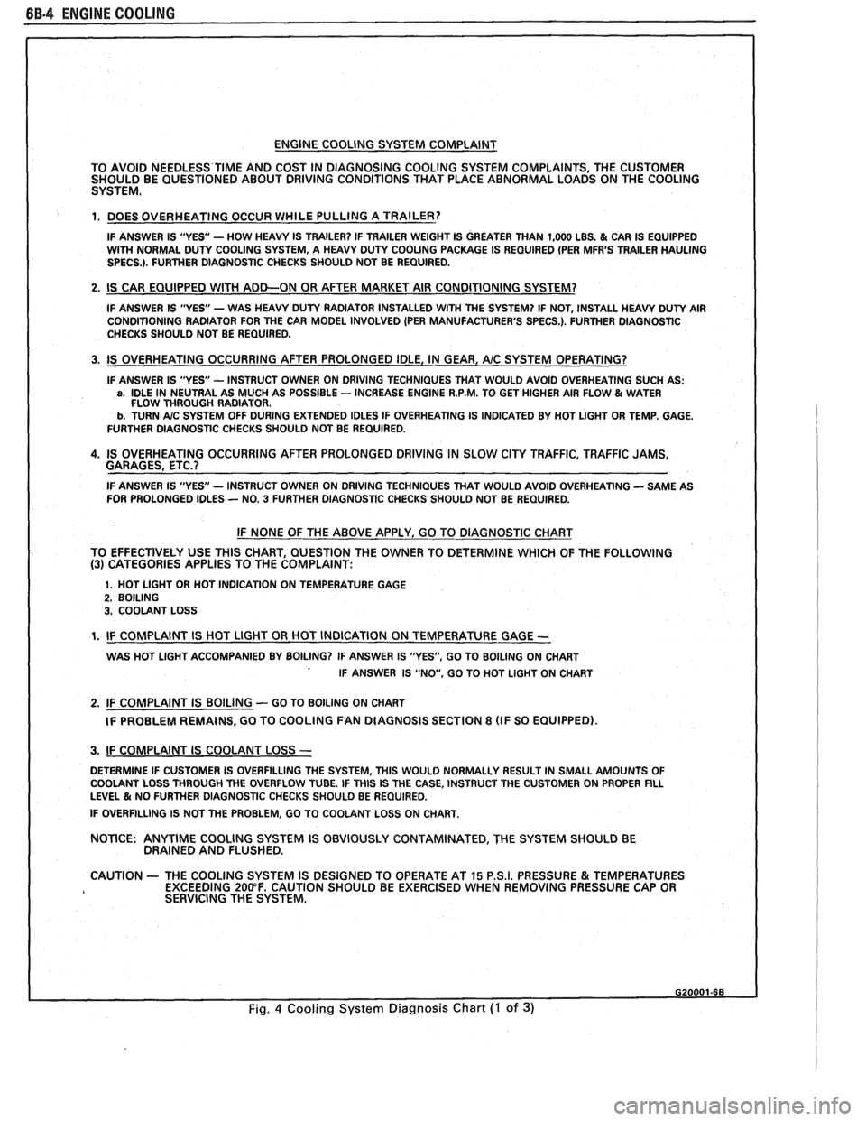
ENGINE COOLING SYSTEM COMPLAINT
TO AVOID NEEDLESS
TIME AND COST IN DIAGNOSING COOLING SYSTEM COMPLAINTS, THE CUSTOMER
SHOULD BE QUESTIONED ABOUT DRIVING CONDITIONS THAT PLACE ABNORMAL LOADS ON THE COOLING
SYSTEM.
1. DOES OVERHEATING OCCUR WHILE PULLING A TRAILER?
IF ANSWER IS "YES'- HOW HEAVY IS TRAILER? IF TRAILER WEIGHT IS GREATER THAN 1,000 LBS. & CAR IS EQUIPPED
WITH NORMAL DUTY COOLING SYSTEM, A HEAVY DUTY COOLING PACKAGE IS REQUIRED (PER MFR'S TRAILER HAULING
SPECS.). FURTHER DIAGNOSTIC CHECKS SHOULD NOT BE REQUIRED.
2. IS CAR EQUIPPED WlTH ADD-ON OR AFTER MARKET AIR CONDITIONING SYSTEM?
IF ANSWER IS "YES"- WAS HEAVY DUTY RADIATOR INSTALLED WITH THE SYSTEM? IF NOT, INSTALL HEAVY DUTY AIR
CONDITIONING RADIATOR FOR THE CAR MODEL INVOLVED (PER MANUFACTURER'S SPECS.). FURTHER DlAGNOSTlC
CHECKS SHOULD NOT BE REQUIRED.
3. IS OVERHEATING OCCURRING AFTER PROLONGED IDLE, IN GEAR, AIC SYSTEM OPERATING?
IF ANSWER IS "YES - INSTRUCT OWNER ON DRIVING TECHNIQUES THAT WOULD AVOID OVERHEATING SUCH AS: a, IDLE IN NEUTRAL AS MUCH AS POSSIBLE - INCREASE ENGINE R.P.M. TO GET HIGHER AIR FLOW & WATER
FLOW THROUGH RADIATOR.
b. TURN A/C SYSTEM OFF DURING EXTENDED IDLES IF OVERHEATING IS INDICATED BY HOT LIGHT OR TEMP. GAGE.
FURTHER DIAGNOSTIC CHECKS SHOULD NOT BE REQUIRED.
4. IS OVERHEATING OCCURRING AFTER PROLONGED DRIVING IN SLOW CITY TRAFFIC, TRAFFIC JAMS,
GARAGES, ETC.?
IF ANSWER IS "YES - INSTRUCT OWNER ON DRIVING TECHNIQUES THAT WOULD AVOID OVERHEATING - SAME AS
FOR PROLONGED IDLES - NO. 3 FURTHER DIAGNOSTIC CHECKS SHOULD NOT BE REQUIRED.
IF NONE OF THE ABOVE APPLY, GO TO DIAGNOSTIC CHART
TO EFFECTIVELY USE THlS CHART, QUESTION THE OWNER TO DETERMINE WHICH OF THE FOLLOWING
(3) CATEGORIES APPLIES TO THE COMPLAINT:
1. HOT LlGHT OR HOT INDICATION ON TEMPERATURE GAGE 2. BOILING 3. COOLANT LOSS
1. IF COMPLAINT IS HOT LlGHT OR HOT INDICATION ON TEMPERATURE GAGE -
WAS HOT LlGHT ACCOMPANIED BY BOILING? IF ANSWER IS "YES", GO TO BOILING ON CHART
IF ANSWER IS "NO, GO TO HOT LlGHT ON CHART
2. IF COMPLAINT IS BOILING - GO TO BOILING ON CHART
IF PROBLEM REMAINS, GO TO COOLING
FAN DIAGNOSIS SECTION 8 (IF SO EQUIPPED).
I 3. IF COMPLAINT IS COOLANT LOSS -
DETERMINE IF CUSTOMER IS OVERFILLING THE SYSTEM, THlS WOULD NORMALLY RESULT IN SMALL AMOUNTS OF
I COOLANT LOSS THROUGH THE OVERFLOW TUBE. IF THlS IS THE CASE, INSTRUCT THE CUSTOMER ON PROPER FILL LEVEL & NO FURTHER DIAGNOSTIC CHECKS SHOULD BE REQUIRED.
I IF OVERFILLING IS NOT THE PROBLEM, GO TO COOLANT LOSS ON CHART.
NOTICE:
ANYTIME COOLING SYSTEM IS OBVIOUSLY CONTAMINATED, THE SYSTEM SHOULD BE
DRAINED AND FLUSHED.
1 CAUTION - THE COOLING SYSTEM IS DESIGNED TO OPERATE AT 15 P.S.I. PRESSURE & TEMPERATURES
EXCEEDING 200°F. CAUTION SHOULD BE EXERCISED WHEN REMOVING PRESSURE CAP OR
I SERVICING THE SYSTEM.
Fig. 4 Cooling System Diagnosis Chart (I of 3)
Page 417 of 1825
6B-8 ENGINE COOLING
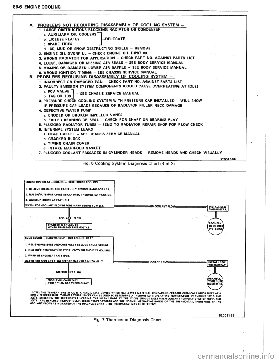
PROBLEMS NOT REQUIRING DISASSEMBLY OF COOLING SYSTEM - 1. LARGE OBSTRUCTIONS BLOCKING RADIATOR OR CONDENSER
a. AUXILIARY OIL COOLERS
b. LICENSE PLATES R ELOCATE
c. SPARE TIRES
d. ICE, MUD OR SNOW OBSTRUCTING GRILLE - REMOVE
2. ENGINE OIL OVERFILL - CHECK ENGINE OIL DIPSTICK
3. WRONG RADIATOR FOR
APPLICATION - CHECK PART NO. AGAINST PARTS LlST
4. LOOSE, DAMAGED OR MISSING AIR SEALS - SEE BODY SERVICE MANUAL
5. MISSING OR DAMAGED LOWER AIR BAFFLE - SEE BODY SERVICE MANUAL
6. WRONG IGNITION TIMING - SEE CHASSIS SERVICE MANUAL PROBLEMS REQUIRING DISASSEMBLY OF COOLING SYSTEM -
1. INCORRECT OR DAMAGED FAN - CHECK PART NO. AGAINST PARTS LlST
2. FAULTY EMISSION SYSTEM COMPONENTS (COULD CAUSE OVERHEATING AT IDLE)
; SEE CHASSIS SERVICE MANUAL
3. PRESSURE CHECK COOLING SYSTEM WITH PRESSURE CAP INSTALLED - WILL SHOW
IF PRESSURE CAP LEAKS BECAUSE OF RADIATOR FILLER NECK DAMAGE
4. DEFECTIVE WATER PUMP
a. ERODED OR BROKEN IMPELLER VANES
b. FAILED BEARING OR SEAL - CHECK FOR SHAFT OR BEARING PLAY
5. PLUGGED RADIATOR TUBES - SEND TO RADIATOR REPAIR SHOP FOR FLOW CHECK
6. INTERNAL SYSTEM LEAKS
B. HEAD GASKET - SEE CHASSIS SERVICE MANUAL
b. CRACKED BLOCK
c. TIMING CHAIN COVER
d. INTAKE MANIFOLD GASKET
7. PLUGGED COOLANT PASSAGES IN CYLINDER HEADS - REMOVE HEADS AND CHECK VISUALLY
Fig. 6 Cooling System Diagnosis Chart (3 of 3)
1. RELIEVE PRESSURE AND CAREFULLY REMOVE RADIATOR CAP.
2. RUB W'F. TEMPERATURE STICK* ONTO THERMOSTAT MOUSING.
3. WARM UP ENGINE AT FAST IDLE:
WATCH FOR COOLANT FLOW BEFORE MAR
NO COOLANT FLOW INSTALL NEW
THERMOSTAT.
COLD ENGINE -SLOW WARMUP -NOT ENOUGH HEAT
1. RELIEVE PRESSURE AND CAREFULLY REMOVE RADIATOR CAP.
2. RUB 188'~. TEMPERATURE STICK' ONTO THERMOSTAT HOUSING.
3. WARM UP ENGINE AT FAST IDLE.
COOLANT FLOW
- 'NOTE: THE TEMPERATURE STICK IS A PENCIL LIKE DEVICE WHICH HAS A WAX MATERIAL CONTAINING CERTAIN CHEMICALS WHICH MELT AT A GIVEN TEMPERATURE THEWERATURE STICKS CAN BE USED TO DETERMINE A THERMOSTAT'S OPERATING TEMPERATURE BY RUBBING laB°F AN0 =OF. STICKS ON THE THERMOSTAT HOUSING. THE MARKS MADE BY THE STICKS SHOULD MELT WHEN COOLANT TEMPERATURES OF IWOF'AND W'F. ARE REACHED, RESPECTIVELY. THESE TEMPERATURES ARE THE NORMAL WERATING RANGE OF THE THERMOSTAT. THEREFORE, ~i WE COOLANT FLOWS AS INDICATED ON THE DIAGNOSIS CHART. THE THERMOSTAT MAY BE DEFECTIVE.
Fig. 7 Thermostat Diagnosis Chart
Page 418 of 1825
ENGINE COOLING BB-7
NOTICE: If recommended quality antifreeze is
used, supplemental inhibitors or additives claiming
to provide increased cooling capability are not
necessary. They may be detrimental to the efficient
operation of the system, and represent an
unnecessary operating expense.
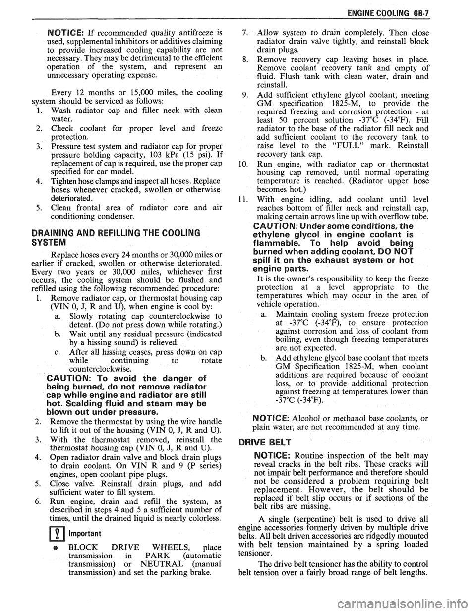
Every 12 months or 15,000 miles, the cooling
system should be serviced as follows;
1. Wash radiator cap and filler neck with clean
water.
2. Check coolant for proper level and freeze
protection.
3. Pressure test system and radiator cap for proper
pressure holding capacity, 103
kPa (15 psi). If
replacement of cap is required, use the proper cap
specified for car model.
4. Tighten hose clamps and inspect all hoses. Replace
hoses whenever cracked, swollen or otherwise
deteriorated.
5. Clean frontal area of radiator core and air
conditioning condenser.
DRAINING AND REFILLING THE COOLING
SYSTEM
Replace hoses every 24 months or 30,000 miles or
earlier if cracked, swollen or otherwise deteriorated.
Every two years or 30,000 miles, whichever first
occurs, the cooling system should be flushed and
refilled using the following recommended procedure:
1. Remove radiator cap, or thermostat housing cap
(VIN
0, J, R and U), when engine is cool by:
a. Slowly
rotating cap counterclockwise to
detent. (Do not press down while rotating.)
b. Wait until any
residual pressure (indicated
by a hissing sound) is relieved.
c. After all hissing ceases, press down on cap
while continuing to rotate
counterclockwise.
CAUTION: To avoid the danger of
being burned, do not remove radiator
cap while engine and radiator are still
hot. Scalding fluid and steam may be
blown out under pressure.
2. Remove the thermostat by using the wire handle
to lift it out of the housing (VIN
0, J, R and U).
3. With the thermostat removed, reinstall the
thermostat housing cap (VIN
0, J, R and U).
4. Open radiator drain valve and block drain plugs
to drain coolant. On VIN R and
9 (P series)
engines, open coolant pipe plugs.
5. Close valve. Reinstall drain plugs, and add
sufficient water to fill system.
6. Run engine, drain and refill the system, as
described in steps
4 and 5 a sufficient number of
times, until the drained liquid is nearly colorless.
Important
BLOCK DRIVE WHEELS, place
transmission in PARK (automatic
transmission) or NEUTRAL (manual
transmission) and set the parking brake. 7.
Allow system to drain completely. Then close
radiator drain valve tightly, and reinstall block
drain plugs.
8. Remove recovery cap leaving hoses in place.
Remove coolant recovery tank and empty of
fluid. Flush tank with clean water, drain and
reinstall.
9. Add sufficient ethylene glycol coolant, meeting
GM specification 1825-M, to provide the
required freezing and corrosion protection
- at
least 50 percent solution -37°C (-34°F). Fill
radiator to the base of the radiator fill neck and
add sufficient coolant to the recovery tank to
raise level to the "FULL" mark. Reinstall
recovery tank cap.
10. Run engine, with radiator cap or thermostat
housing cap removed, until normal operating
temperature is reached. (Radiator upper hose
becomes hot.)
11. With engine idling, add coolant until level
reaches bottom of filler neck and reinstall cap,
making certain arrows line up with overflow tube.
CAUTION: Under some conditions, the
ethylene glycol in engine coolant is
flammable. To help avoid being
burned when adding coolant, DO NOT
spill
it on the exhaust system or hat
engine parts.
It is the owner's responsibility to keep the freeze
protection at a level appropriate to the
temperatures which may occur in the area of
vehicle operation.
a. Maintain
cooling system freeze protection
at
-37°C (-34"F), to ensure protection
against corrosion and loss of coolant from
boiling, even though freezing temperatures
are not expected.
b. Add ethylene glycol base coolant that meets
GM Specification 1825-M, when coolant
additions are required because of coolant
loss, or to provide additional protection
against
freezing at temperatures lower than
-37°C (-34°F).
NOTICE: Alcohol or methanol base coolants, or
plain water, are not recommended at any time.
DRlVE BELT
NOTICE: Routine inspection of the belt may
reveal cracks in the belt ribs. These cracks will
not impair belt performance and therefore should
not be considered a problem requiring belt
replacement. However, the belt should be
replaced if belt slip occurs or if sections of the
belt ribs are missing.
A single (serpentine) belt is used to drive all
engine accessories formerly driven by multiple drive
belts. All belt driven accessories are ridgedly mounted
with belt tension maintained by a spring loaded
tensioner.
The drive belt tensioner has the ability to control
belt tension over a fairly broad range of belt lengths.
Page 419 of 1825
68-8 ENGINE COOLING
However, there are limits to the tensioner's ability to
The tensioner has rovisions for a visual check to
compensate for varying lengths of belts. With the
ten- verify that it is in t e "operating range" (see Figures
sioner outside of its operating range, poor tension
608 and 609). R
control andlor damage to the tensioner may result.
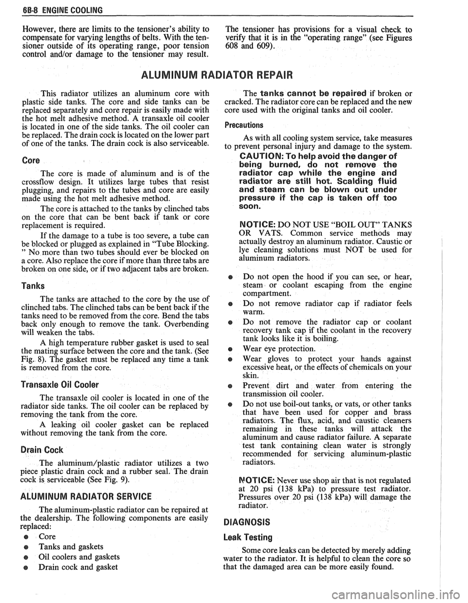
ALUMINUM RADIATOR REPAIR
This radiator utilizes an aluminum core with
plastic side tanks. The core and side tanks can be
replaced separately and core repair is easily made with
the hot melt adhesive method. A transaxle oil cooler
is located in one of the side tanks. The oil cooler can
be replaced. The drain cock is located on the lower part
of one of the tanks. The drain cock is also serviceable.
Core
The core is made of aluminum and is of the
crossflow design. It utilizes large tubes that resist
plugging, and repairs to the tubes and core are easily
made using the hot melt adhesive method.
The core is attached to the tanks by clinched tabs
on the core that can be bent back if tank or core
replacement is required.
If the damage to a tube is too severe, a tube can
be blocked or plugged as explained in "Tube Blocking.
" No more than two tubes should ever be blocked on
a core. Also replace the core if more than three tabs are
broken on one side, or if two adjacent tabs are broken.
Tanks
The tanks are attached to the core by the use of
clinched tabs. The clinched tabs can be bent back if the
tanks need to be removed from the core. Bend the tabs
back only enough to remove the tank. Overbending
will weaken the tabs.
A high temperature rubber gasket is used to seal
the mating surface between the core and the tank. (See
Fig. 8). The gasket must be replaced any time a tank
is removed from the core.
Transaxle Oil Cooler
The transaxle oil cooler is located in one of the
radiator side tanks. The oil cooler can be replaced by
removing the tank from the core.
A leaking oil cooler gasket can be replaced
without removing the tank from the core.
Drain Cock
The aluminum/plastic radiator utilizes a two
piece plastic drain cock and a rubber seal. The drain
cock is serviceable (See Fig.
9).
ALUMINUM RADIATOR SERVICE
The aluminum-plastic radiator can be repaired at
the dealership. The following components are easily
replaced:
e Core
e Tanks and gaskets
o Oil coolers and gaskets
e Drain cock and gasket The
tanks cannot be repaired if broken or
cracked. The radiator core can be replaced and the new
core used with the original tanks and oil cooler.
Precautions
As with all cooling system service, take measures
to prevent personal injury and damage to the system.
CAUTION: To help avoid the danger of
being burned, do not remove the
radiator cap while the engine and
radiator are
still hot. Scalding fluid
and steam can be blown out under
pressure if the
cap is taken off too
soon.
NOTICE: DO NOT USE "BOIL OUT" TANKS
OR VATS. Common service methods may
actually destroy an aluminum radiator. Caustic or
lye cleaning solutions must NOT be used for
aluminum radiators.
e Do not open the hood if you can see, or hear,
steam or coolant escaping from the engine
compartment.
e Do not remove radiator cap if radiator feels
warm.
e Do not remove the radiator cap or coolant
recovery tank cap if the coolant in the recovery
tank looks like it is boiling.
Wear eye protection.
e Wear gloves to protect your hands against
excessive heat, or the effects of chemicals on your
skin.
o Prevent dirt and water from entering the
transmission oil cooler.
e Do not use boil-out tanks, or vats, or other tanks
that have been used for copper and brass
radiators. The flux, acid, and caustic cleaners
remaining in these tanks will attack the
aluminum and cause radiator failure.
A separate
test tank containing clean water is strongly
recommended for servicing aluminum-plastic
radiators.
RIOTICE: Never use shop air that is not regulated
at
20 psi (138 kPa) to pressure test radiator.
Pressures over
20 psi (138 kPa) will damage the
radiator.
DIAGNOSIS
Leak Testing
Some core leaks can be detected by merely adding
water to the radiator. It is helpful to clean the core so
that the damaged area can be more easily found.
Page 420 of 1825
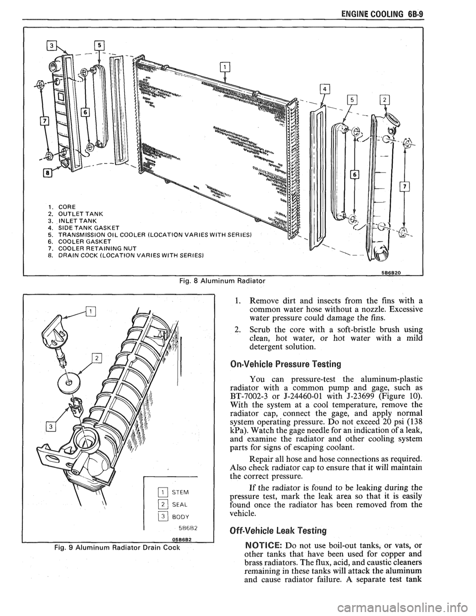
ENGINE COOLING 6B-9
Fig. 8 Aluminum Radiator
2 SEAL
3 BODY I
1. Remove
dirt and insects from the fins with a
common water hose without a nozzle. Excessive
water pressure could damage the fins.
2. Scrub the core with a soft-bristle brush using
clean, hot water, or hot water with a mild
detergent solution.
On-Vehicle Pressure Testing
You can pressure-test the aluminum-plastic
radiator with a common pump and gage, such as
BT-7002-3 or J-24460-01 with J-23699 (Figure 10).
With the system at a cool temperature, remove the
radiator cap, connect the gage, and apply normal
system operating pressure. Do not exceed 20 psi (138
kPa). Watch the gage needle for an indication of a leak,
and examine the radiator and other cooling system
parts for signs of escaping coolant.
Repair all hose and hose connections as required.
Also check radiator cap to ensure that it will maintain
the correct pressure.
If the radiator is found to be leaking during the
pressure test, mark the leak area so that it is easily
found once the radiator has been removed from the
vehicle.
Off-Vehicle beak Testing
Fig. 9 Aluminum Radiator Drain Cock NOTICE: Do not use boil-out tanks, or vats, or
other tanks that have been used for
couuer and
brass radiators. The flux, acid, and
caustiE cleaners
remaining in these tanks will attack the aluminum
and cause radiator failure. A separate test tank
Page 421 of 1825
6B-10 ENGINE COOLING
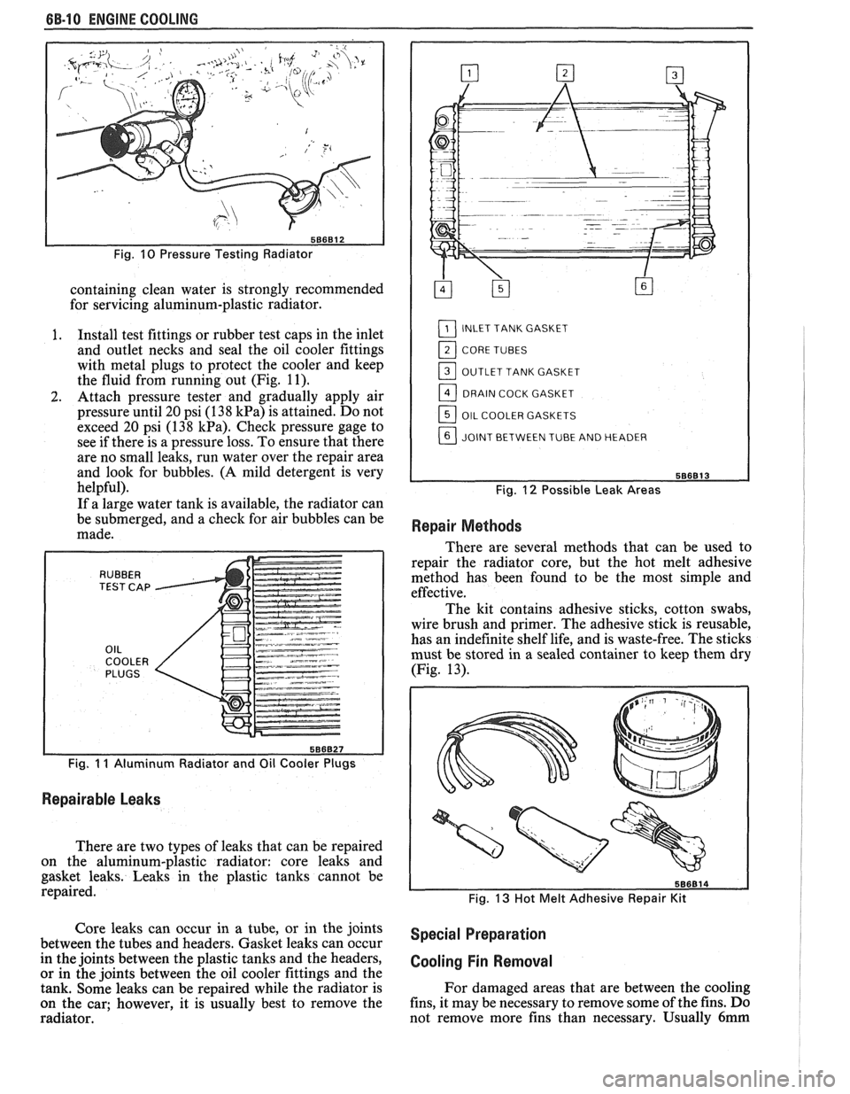
Fig. 10 Pressure Testing Radiator
containing clean water is strongly recommended
for servicing aluminum-plastic radiator.
I. Install test fittings or rubber test caps in the inlet
and outlet necks and seal the oil cooler fittings
with metal plugs to protect the cooler and keep
the fluid from running out (Fig.
11).
2. Attach pressure tester and gradually apply air
pressure until 20 psi (1
38 kPa) is attained. Do not
exceed 20 psi (138
kPa). Check pressure gage to
see if there is a pressure loss. To ensure that there
are no small leaks, run water over the repair area
and look for bubbles.
(A mild detergent is very
helpful).
If a large water tank is available, the radiator can
be submerged, and a check for air bubbles can be
made.
Fig. I I Aluminum Radiator and Oil Cooler Plugs
Repairable Leaks
There are two types of leaks that can be repaired
on the aluminum-plastic radiator: core leaks and
gasket leaks. Leaks in the plastic tanks cannot be
repaired.
L1_] INLET TANK GASKET
11_] CORE TUBES
OUTLET TANK GASKET
DRAIN COCK GASKET
OIL COOLER GASKETS
JOINT BETWEEN TUBE AND HEADER
Fig. 12 Possible Leak Areas
Repair Methods
There are several methods that can be used to
repair the radiator core, but the hot melt adhesive
method has been found to be the most simple and
effective.
The kit contains adhesive sticks, cotton swabs,
wire brush and primer. The adhesive stick is reusable,
has an indefinite shelf life, and is waste-free. The sticks
must be stored in a sealed container to keep them dry
(Fig. 13).
Fig. 13 Hot Melt Adhesive Repair Kit
Core leaks can occur in a tube, or in the joints special preparation between the tubes and headers. Gasket leaks can occur
in the joints between the plastic tanks and the headers,
cooling Fin Removal or in the joints between the oil cooler fittings and the
tank. Some leaks can be repaired while the radiator is For
damaged areas that are between the cooling
on the car; however, it is usually best to remove the fins,
it may be necessary to remove some of the fins. Do
radiator. not remove more fins
than necessary. Usually
6mm
Page 432 of 1825
ENGINE FUEL BC-1
SECTION 6C
NE FUEL
CONTENTS
General Description ..................................... 6C-1 Fuel
Cap ........................................................... 6C-3
.................................................. ............................................. Alcohol-In-Fuel 6C- 1 Fuel Filter Neck 6C-3
................... ............ Fuel Metering .................................................. 6C-2 Fuel Gage Sending Unit .. 6C-4
....................... ............................... Throttle Body Injection (TBI) .... 6C-2 Diagnosis ,. 6C-4 ................... Service
Procedures ............................................. 6C-4
Port Fuel Injection ...................................... 6C-2
Pressure Relief ........................................... 6C-4
Fuel Feed and Return Pipe
............................... 6C-2
Flow Test .................................................... 6C-4
Fuel Pipes (MPFI)
.......................................... 6C-3
Pressure Test - TBI ................................... 6C-4
Fuel and Vapor Hoses
....................................... 6C-3
Pressure Test - MPFI .................................... 6C-4
Fuel Pump ........................................................ 6C-3 ...................................................... Fuel Pump Relay .............................................. 6C-3 Fuel Tank 6C-4
Fuel Filter
......................................................... 6C-3 Accelerator Controls ...................................... 6C-5
Fuel Tank
....................................................... 6C-3
All new General Motors vehicles are certified by
the United States Environmental Protection Agency as
conforming to the requirements of the regulations for
the control of air pollution from new motor vehicles.
This certification is contingent on certain adjustments
being set to factory standards. In most cases, these
adjustment points either have been permanently
sealed and/or made inaccessible to prevent
indiscriminate or routine adjustment in the field. For
this reason, the factory procedure for temporarily
removing plugs, caps, etc., for purposes of servicing the
product must be strictly followed and, wherever
practicable, returned to the original intent of the
design.
GENERAL DESCRIPTION
All gasoline engines are designed to use only
unleaded gasoline. Unleaded gasoline must be used for
proper emission control system operation. Its use will
also minimize spark plug fouling and extend engine oil
life. Using leaded gasoline can damage the emission
control system and could result in loss of emission
warranty coverage.
All cars are equipped with an Evaporative
Emission System. The purpose of the system is to
minimize the escape of fuel vapors to the atmosphere.
Information on this system will be found in Section
6E2, or 6E3.
When working on the fuel system, there are
several things to keep in mind.
@ Any time fuel system is being worked on,
disconnect the negative battery cable
except for those tests where battery
Adhere to all Notices and Cautions.
Always keep a dry chemical (Class B) fire
extinguisher near the work area.
-
Always use a backup wrench when loosening or
tightening a screw couple fitting.
The torque on a screw fitting is
30 N-m (22 lb.
ft.).
Pipe is used on all MPFI, TPI, SFI, and TBI
applications. Fittings require the use of an
"0"
Ring. Replace all pipe with the same type of pipe
and fittings that were removed.
All fuel pipes must meet GM Specification
124-M, or its equivalent.
All fuel hoses must meet GM Specification
6163-M, or its equivalent.
Do not replace fuel pipe with fuel hose.
voltage is required.
@ On MPFI, TPI, SF1 and TBI systems, always A1cohol-ln-Fuel
relieve the line pressure before servicing any fuel Certain driveability complaints such as
system components. hesitation, lack of power, stall, no start, etc., may be
@ Do not repair the fuel system until you have read caused
by an excessive amount of alcohol-in-fuel. The
the copy and checked the illustrations relating to complaints
may be due to fuel system corrosion and
that repair. subsequent
fuel filter plugging, deterioration of rubber
Page 433 of 1825

6C-2 ENGINE FUEL
components such as the accelerator pumps and/or
air-fuel mixture leaning effects.
Various types and concentrations of alcohols are
used in commercial gasoline. Some alcohols are more
detrimental to fuel system components than others. If
an excessive amount of alcohol in the fuel is suspected
as the cause of a driveability condition, the following
procedure may be used to detect the presence of
alcohol in the fuel.
In this procedure, water is used to
extract the alcohol from the fuel. However, the specific
type of alcohol is not determined.
The fuel sample should be drawn from the
bottom part of the tank so that any water, if already
present, can be detected. The sample should be bright
and clear. If the sample appears cloudy or
contaminated with water as indicated by a water layer
in the bottom part of the sample, this procedure should
not be used. The fuel system should then be cleaned
(See Fuel System Cleaning).
Testing Procedure
1. Using a 100 ml cylinder with 1 ml graduation
marks, fill with fuel to the 90 ml mark.
2. Add 10 ml of water to bring the total fluid volume
to 100 ml and install a stopper.
3. Shake vigorously for 10 to 15 seconds.
4. Carefully loosen stopper to release pressure.
5. Close the stopper and shake vigorously again for
10 to 15 seconds.
6. Carefully loosen
stopper to release pressure.
7. Put the graduated cylinder on a level surface for
approximately 5 minutes to allow adequate liquid
separation.
If alcohol is present in the fuel, the volume of the
lower layer, which would now contain alcohol and
water will be greater than 10 ml. For example, if the
volume of the lower layer is increased to 15 ml, it
would indicate at least 5 percent alcohol in fuel. The
actual amount of alcohol may be somewhat greater
because this procedure does not extract all of the
alcohol from the fuel.
FUEL METERING
Throttle Body lnjection
(TBI)
With Throttle Body Injection (TBI), an injection
unit is placed on the intake manifold where the
carburetor is normally mounted. The TBI unit is
computer controlled and supplies the correct amount
of fuel during all engine operating conditions. See
Section 6E2 for information relative to operation and
diagnosis of TBI units.
Port Fuel lnjection
The ECM is in complete control of this fuel
delivery system during all driving conditions.
The intake manifold is used only to let air into the
engine. Fuel is injected by separate injectors that are
mounted over the intake valve.
With the Port Injection System, there is no need
for a Thermac, EFE, Map Sensor, Baro Sensor, A.I.R.
System, or Dual Bed Converter. This
system provides better cold driveability,
lower exhaust emissions and better throttle response.
In Sequential Fuel Injection systems (SFI),
injectors turn on at every crankshaft revolution. The
ECM controls the injector "on" time so that the
correct amount of fuel is metered, depending on
driving conditions.
Two interchangeable
"0" rings are used on the
injector that must be inspected when the injectors are
removed. Check
"0" rings for cuts or other type of
damage and replace as necessary.
The air cleaner is remotely mounted near the
radiator. It is connected to the intake manifold by air
intake ducting.
Also, mounted between the air cleaner and
intake, are the mass air flow sensor and throttle body.
Cold driveability characteristics are greatly
improved with the aid of an engine coolant supply to
the throttle body for rapid warm up.
The throttle body design uses an integral Idle Air
Control to govern idle speed and a Throttle Position
Sensor (TPS). The IAC and TPS are both controlled
by the ECM.
A large diameter fuel rail is attached to the intake
manifold and supplies fuel to all the injectors.
A fuel pressure tap is located on the rail for quick
pressure checks.
Fuel is recirculated through the rail continually
while the engine is running. This removes air and
vapors from the fuel as well as keeping the fuel cool
during hot weather operation.
A fuel pressure regulator is mounted on the fuel
rail. It maintains a constant 36 psi pressure across the
injectors under all operating conditions. It is
accomplished by controlling the amount of fuel that is
recirculated back to the fuel tank, based on engine
demand.
The pressure regulator also uses an
"0" ring for
attachment. The
"0" ring used is the same one that is
used for the injectors.
Some engines also have an accumulator that is
located in the fuel feed line near the cowl area. It is used
to dampen the vibration that is caused by the
pressurized fuel and the pulsing of the injector.
See Section 6E3 for more information and
diagnosis.
Fuel Feed and Return Pipe
When replacing fuel feed and return pipes, always
replace them with welded steel tubing meeting GM
Specification
124M, or its equivalent. The replacement
pipe must use the same type of fittings as the original
pipes to ensure the integrity of the connection.
NOTICE: Do not replace fuel pipe with fuel hose
or any other type of tubing such as copper or
aluminum. Only tubing meeting the 124M
specification is capable of meeting all the pressure
and vibration characteristics necessary to ensure
the durability standard required.
Always check and replace any
"0" rings or
washers that appear damaged.