1988 PONTIAC FIERO check engine
[x] Cancel search: check enginePage 387 of 1825
6A3-8 V-8 ENGINE
10. Remove exhaust pipe nuts.
1 1. Lower vehicle.
12. Remove manifold bolts.
13. Remove manifold.
Installation
1. Clean mating surfaces on manifold and head,
then install manifold in position and install bolts
finger tight.
2. Torque bolts to specifications.
3. Reverse removal procedures.
4. Adjust necessary drive belts.
P
IN.)
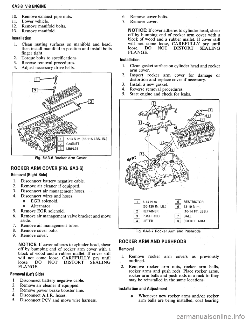
Fig. 6A3-6 Rocker Arm Cover
ROCKER ARM COVER (FIG. 6A3-6)
Removal (Right Side)
1. Disconnect battery negative cable.
2. Remove air cleaner if equipped.
3. Disconnect air management hoses.
4. Disconnect wires and hoses.
EGR solenoid.
e Alternator
5. Remove EGR solenoid.
6. Remove air management valve bracket and move
aside.
7. Remove air management tubes.
8. Remove cover bolts.
9. Remove cover.
N OTI G E: If cover adheres to cylinder head, shear
off by bumping end of rocker arm cover with a
block of wood and a rubber mallet. If cover still
will not come loose, CAREFULLY pry until
loose. DO NOT DISTORT SEALING
FLANGE.
Removal (Left Side)
1. Disconnect battery negative cable.
2. Remove air cleaner if equipped.
3. Remove Power brake booster line.
4. isc connect A.I.R. hoses.
5. Disconnect PCV and move wire harness.
6. Remove cover bolts.
7. Remove cover.
NOTICE: If cover adheres to cylinder head, shear
off by bumping end of rocker arm cover with a
block of wood and a rubber mallet. If cover still
will not come loose, CAREFULLY pry until
loose. DO NOT DISTORT SEALING
FLANGE.
lnstallation
1. Clean gasket surface on cylinder head and rocker
arm cover.
2. Inspect rocker arm cover for damage or
distortion and replace cover if necessary.
3. Install a new gasket.
4. Reverse removal procedures.
5. Start engine and check for leaks.
6-14 N.m RESTRICTOR
(55-125 IN.
LB.) 161 13-19 N,rn - 1 RETAINER (10-14 FT. LBS.)
/ PUSH ROD a BALL
a LIFTER 1 ROCKER ARM
Fig. 6A3-7 Rocker Arm and Pushrods
ROCKER ARM AND PUSHRODS
Removal
1. Remove rocker arm covers as previously
outlined.
2. Remove rocker arm nuts, rocker arm balls,
rocker arms and push rods. Place rocker arms,
rocker arm balls and push rods in a rack to they
may be reinstalled in the same locations.
Installation and Adjustment
e Whenever new rocker arms and/or rocker
arm balls are being installed, coat bearing
Page 389 of 1825
QA3-10 V-8 ENGINE
lnstallation
1. Install valve stem seal over valve stem and seat
against head.
2. Set
the valve spring and damper, oil shedder and
valve cap in place. Compress the spring with Tool
J-5892 and install oil seal in the lower groove of
the stem, making sure the seal is flat and not
twisted. A light coat of oil on the seal will help
prevent twisting.
3. Install
the valve locks and release the compressor
tool making sure the locks seat properly in the
upper groove of the valve stem. Grease may be
used to hold the locks in place while releasing the
compressor tool.
4. Using tool J-23994, apply vacuum to the valve
cap to make sure no air leaks past the seal.
5. Install spark plug and torque to 22 lb. ft.
(30N.m).
6. Install and adjust valve mechanism as previously
outlined.
VALVE LIFTERS
Hydraulic valve lifters very seldom require
attention. The lifters are extremely simple in design,
readjustments are not necessary, and servicing of the
lifters requires only that care and cleanliness be
exercised in the handling of parts.
Valve Lifter Diagnosis
1.
Momentarily Noisy When Car is Started:
This condition is normal. Oil drains from the
lifters which are holding the valves open when the
engine is not running. It will take a few seconds
for the lifter to fill after the engine is started.
2. Intermittently Noisy On Idle Only. Disappearing
When Engine Speed is Increased:
Intermittent clicking may be an indication of a
pitted check valve ball, or it may be caused by
dirt.
Correction: Clean the lifter and inspect. If check
valve ball is defective, replace lifter.
3. Noisy At Slow Idle Or With Hot Oil, Quiet With
Cold Oil Or As Engine Speed Is Increased:
High leak down rate. Replace suspect lifter.
4. Noisy At High Car Speeds And Quiet At Low
Speeds:
a. High oil level
- Oil level above the "Full"
mark allows crankshaft counterweights to
churn the oil into foam. When foam is
pumped into the lifters, they will become
noisy since a solid column of oil is required
for proper operation. Correction: Drain oil
inti1 proper level is obtained.
b. Low oil level - Oil level below the "Add"
mark allows the pump to pump air at high
speeds which results in noisy lifters.
Correction: Fill until proper oil level is
obtained.
c. Oil pan bent on bottom or pump screen
cocked or loose, replace or repair as
necessary. 5.
Noisy At Idle Becoming Louder As Engine Speed
Is Increased To 1500 rpm:
This noise is not connected with lifter
malfunction. It becomes most noticeable in the
car at 10 to 15 mph "1" (Low) range, or 30 to
35
mph "DM (Drive) range and is best described as
a
hashy sound. At slow idle, it may be entirely
gone or appear as a light ticking noise in one or
more valves. It is caused by one or more of the
following:
a. Badly worn or scuffed valve tip and rocker
arm pad.
b. Excessive valve stem to guide clearance.
c. Excessive valve seat
runout.
d. Off square valve spring.
e. Excessive valve face
runout.
f. Valve spring damper clicking on rotator.
Removal
1.
Remove intake manifold as previously outlined.
2. Remove valve mechanism as previously outlined.
3. Remove valve lifter retainer.
4. Remvoe valve lifter restrictor.
5. Remove valve lifters (Fig.
6A3-7). Place valve
lifters in a rack so that they may be reinstalled in
the same location.
Installation
1.
Coat roller of valve lifters with "Molykote" or its
equivalent and install valve lifters.
2. Install valve lifter restrictor.
3. Install valve lifter retainer.
4. Install intake manifold as previously outlined.
5. Install and adjust valve mechanism as outlined.
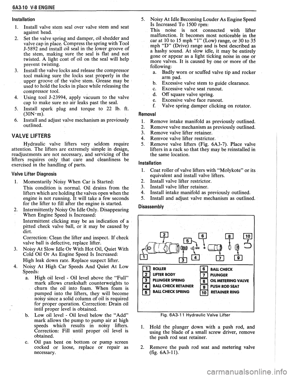
Disassembly
PLUNGER SPRING
Fig. 6A3-1 1 Hydraulic Valve Lifter
1. Hold the plunger down with a push rod, and
using the blade of a small screw driver, remove
the push rod seat retainer.
2. Remove the push rod seat and metering valve
(fig.
6A3- 1 1).
Page 390 of 1825
V-8 ENGINE BA3-11
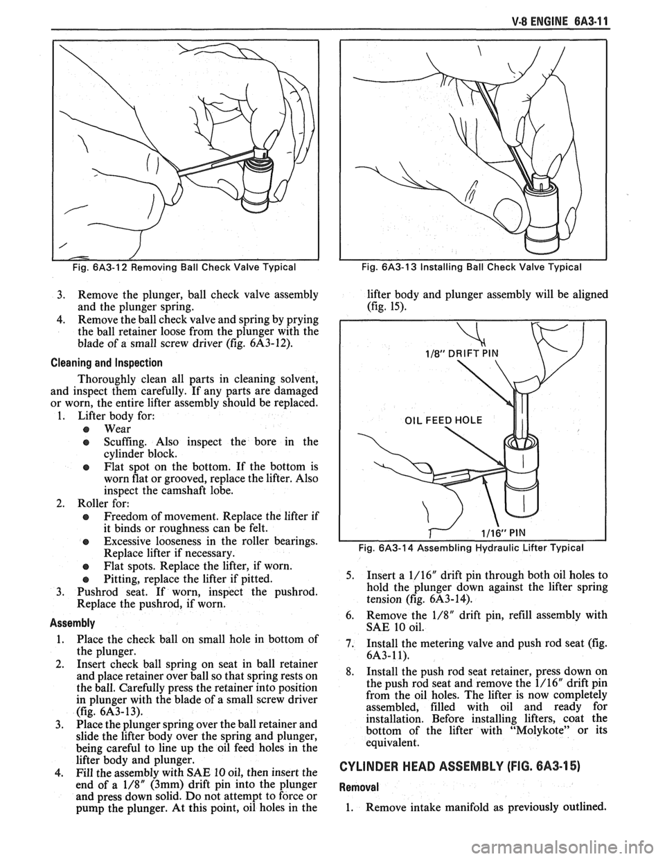
Fig. 6/43-12 Removing Ball Check Valve Typical
3. Remove the plunger, ball check valve assembly
and the plunger spring.
4. Remove
the ball check valve and spring by prying
the ball retainer loose from the plunger with the
blade of a small screw driver (fig.
6A3-12).
Cleaning and Inspection
Thoroughly clean all parts in cleaning solvent,
and inspect them carefully. If any parts are damaged
or worn, the entire lifter assembly should be replaced.
1. Lifter body for:
@ Wear
e Scuffing. Also inspect the bore in the
cylinder block.
@ Flat spot on the bottom. If the bottom is
worn flat or grooved, replace the lifter. Also
inspect the camshaft lobe.
2. Roller for:
@ Freedom of movement. Replace the lifter if
it binds or roughness can be felt.
@ Excessive looseness in the roller bearings.
Replace lifter if necessary.
e Flat spots. Replace the lifter, if worn.
e Pitting, replace the lifter if pitted.
3.
Pushrod seat. If worn, inspect the pushrod.
Replace the pushrod, if worn.
Assembly
1. Place the check ball on small hole in bottom of
the plunger.
2. Insert check ball spring on seat in ball retainer
and place retainer over ball so that spring rests on
the ball. Carefully press the retainer into position
in plunger with the blade of a small screw driver
(fig.
6A3- 13).
3. Place the
plunger spring over the ball retainer and
slide the lifter body over the spring and plunger,
being careful to line up the oil feed holes in the
lifter body and plunger.
4. Fill the assembly with SAE 10 oil, then insert the
end of a
1/8" (3mm) drift pin into the plunger
and press down solid. Do not attempt to force or
pump the plunger. At this point, oil holes in the
Fig. 6A3-13 Installing Ball Check Valve Typical
lifter body and plunger assembly will be aligned
(fig. 15).
Fig. 6A3-14 Assembling Hydraulic Lifter Typical
5. Insert a
1/16" drift pin through both oil holes to
hold the plunger down against the lifter spring
tension (fig.
6A3-14).
6. Remove
the 1/8" drift pin, refill assembly with
SAE 10 oil.
7. Install the metering valve and push rod seat (fig.
6A3-11).
8. Install the push rod seat retainer, press down on
the push rod seat and remove the 1/16" drift pin
from the oil holes. The lifter is now completely
assembled, filled with oil and ready for
installation. Before installing lifters, coat the
bottom of the lifter with "Molykote" or its
equivalent.
CYLINDER HEAD ASSEMBLY (FIG. 6A3-15)
Removal
1. Remove intake manifold as previously outlined.
Page 392 of 1825
V-8 ENGINE 6A3-13
reading. If clearance exceeds specifications,
it will be necessary to ream valve guides for
oversize valves.
e Service valves are available in standard,
.003", .015" and .030n oversize.
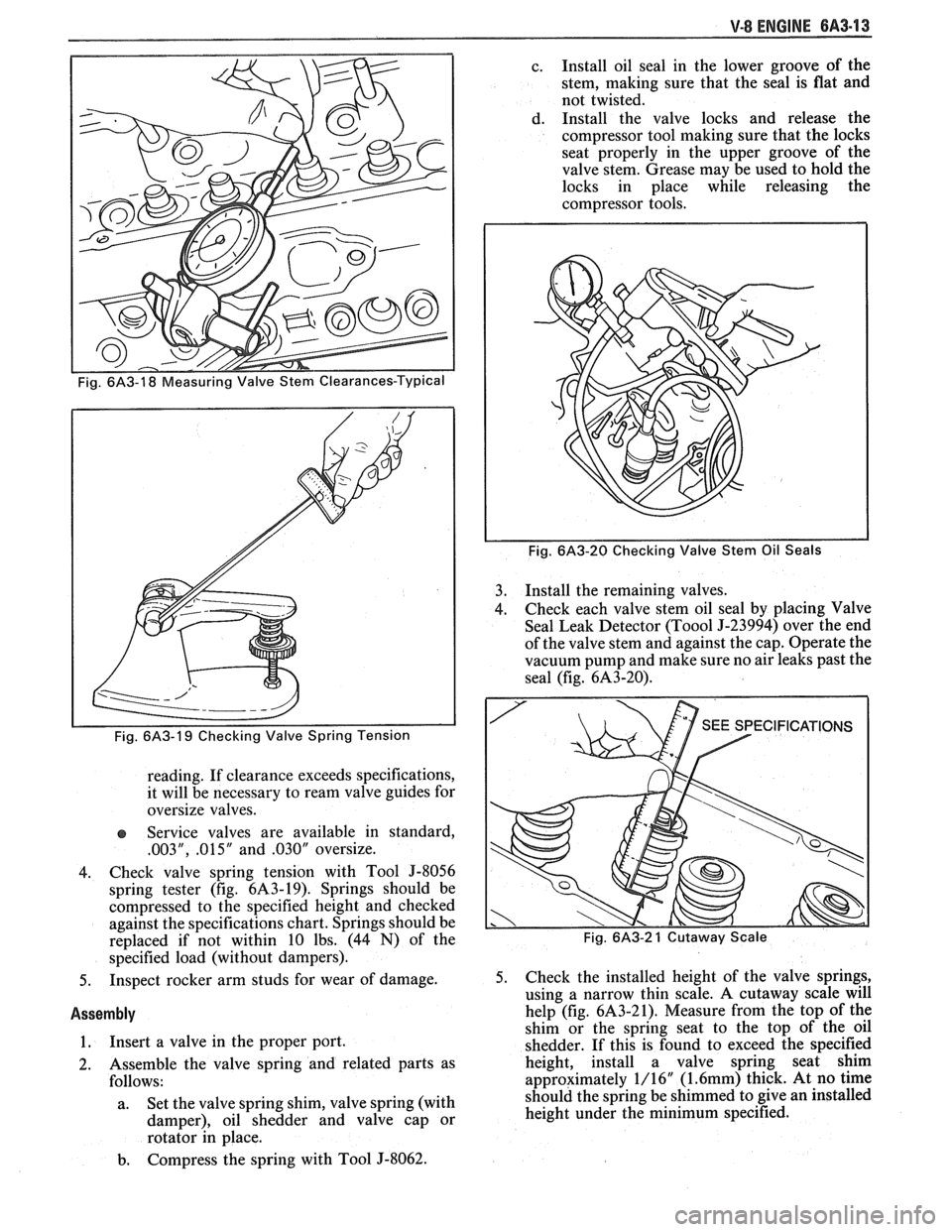
4. Check valve spring tension with Tool
5-8056
spring tester (fig. 6143-19). Springs should be
compressed to the specified height and checked
against the specifications chart. Springs should be
replaced if not within 10 lbs. (44
N) of the
specified load (without dampers).
5. Inspect rocker arm studs for wear of damage.
Assembly
1. Insert a
valve in the proper port.
2. Assemble the valve spring and related parts as
follows:
a. Set
the valve spring shim, valve spring (with
damper), oil shedder and valve cap or
rotator in place.
b. Compress the spring with Tool J-8062. c.
Install oil seal in the lower groove of the
stem, making sure that the seal is flat and
not twisted.
d. Install the valve locks and release the
compressor tool making sure that the locks
seat properly in the upper groove of the
valve stem. Grease may be used to hold the
locks in place while releasing the
compressor tools.
Fig. 6A3-20 Checking Valve Stem Oil Seals
3. Install the remaining valves.
4. Check each
valve stem oil seal by placing Valve
Seal Leak Detector
(Too01 9-23994) over the end
of the valve stem and against the cap. Operate the
vacuum pump and make sure no air leaks past the
seal (fig.
6A3-20).
Fig. 6A3-2 1 Cutaway Scale
5. Check the installed height of the valve springs,
using a narrow thin scale. A cutaway scale will
help (fig.
6A3-21). Measure from the top of the
shim or the spring seat to the top of the oil
shedder. If this is found to exceed the specified
height, install a valve spring seat shim
approximately 1/16"
(1.6mm) thick. At no time
should the spring be shimmed to give an installed
height under the minimum specified.
Page 397 of 1825
6A3-18 V-8 ENGINE
bore, remove remover and installer tool and
bearing from puller screw.
5. Remove remaining bearings (except front and
rear) in the same manner. It will be necessary to
index pilot in camshaft rear bearing to remove the
rear intermediate bearing.
6. Assemble remover
and installer tool on driver
handle and remove camshaft front and rear
bearings by driving towards center of cylinder
block.
lnstallation
The camshaft front and rear bearings should be
installed first. These bearings will act as guides for the
pilot and center the remaining bearings being pulled
into place.
1. Assemble remover
and installer tool on driver
handle and install camshaft front and rear
bearings by driving towards center of cylinder
block.
2. Using Tool Set J-6098, with nut then thrust
washer installed to end of threads, index pilot in
camshaft front bearing and install puller screw
through pilot.
3. Index camshaft bearing in bore (with oil hole
aligned as outlined below), then install remover
and installer tool on puller screw with shoulder
toward bearing.
e Number one cam bearing oil hole must be
positioned so that oil holes are equidistant
from 6 o'clock position.
e Number two through number four bearing
oil holes must be positioned at 5 o'clock
position (toward left side of engine and at a
position even with bottom of cylinder bore).
e Number five bearing oil hole must be in 12
o'clock position.
4. Using two wrenches, hold puller screw while
turning nut. After bearing has been pulled into
bore, remove the remover and installer tool from
puller screw and check alignment of oil hole in
camshaft bearing.
5. Install remaining bearings in the same manner. It
will be necessary to index pilot in the camshaft
rear bearing to install the rear intermediate
bearing.
6. Coat new camshaft rear plug O.D. with
# 1052080 sealant, or equivalent, and install
flush to 1/32"
(.80mm) deep.
OIL PAN
Removal
1. Disconnect battery negative cable.
2. Remove fan shroud.
3. Remove air cleaner and lay aside if equipped.
4. Remove distributor cap and lay aside.
5. Raise vehicle.
6. Drain crankcase.
7. Disconnect exhaust pipe at manifold.
8. Disconnect AIR pipe clamp.
9. Disconnect converter hanger bolts and allow
exhaust to hang down.
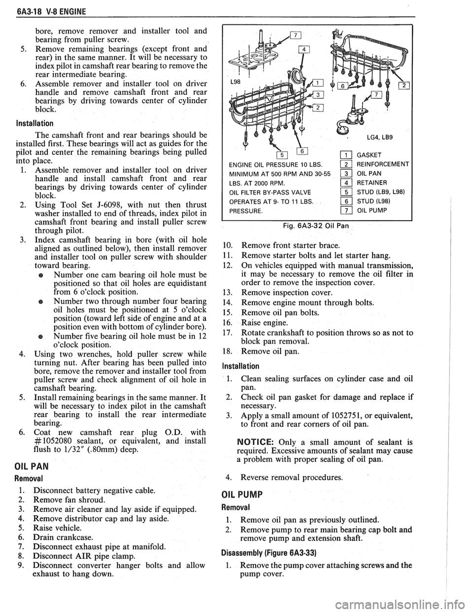
GASKET
ENGINE OIL PRESSURE 10 LBS.
1 REINFORCEMENT
MINIMUM AT 500 RPM AND 30-55
1 OIL PAN
LBS. AT 2000 RPM.
161 RETAINER
OIL FILTER BY-PASS VALVE STUD
(LB9, L98)
OPERATES
AT 9- TO 11 LBS. STUD (L98)
PRESSURE.
OIL PUMP
Fig. 6A3-32 Oil Pan
10. Remove front starter brace.
11. Remove starter bolts and let starter hang.
12. On vehicles equipped with manual transmission,
it may be necessary to remove the oil filter in
order to remove the inspection cover.
13. Remove inspection cover.
14. Remove engine mount through bolts.
15. Remove oil pan bolts.
16. Raise engine.
17. Rotate crankshaft to position throws so as not to
block pan removal.
18. Remove oil pan.
lnstallation
1.
Clean sealing surfaces on cylinder case and oil
pan.
2. Check oil pan gasket for damage and replace if
necessary.
3. Apply a small amount of 1052751, or equivalent,
to front and rear corners of oil pan.
NOTICE: Only a small amount of sealant is
required. Excessive amounts of sealant may cause
a problem with proper sealing of oil pan.
4. Reverse removal procedures.
OIL PUMP
Removal
1. Remove oil pan as previously outlined.
2. Remove pump to rear main bearing cap bolt and
remove pump and extension shaft.
Disassembly (Figure 6A3-33)
1. Remove the pump cover attaching screws and the
pump cover.
Page 398 of 1825
V-8 ENGINE 6A3-19
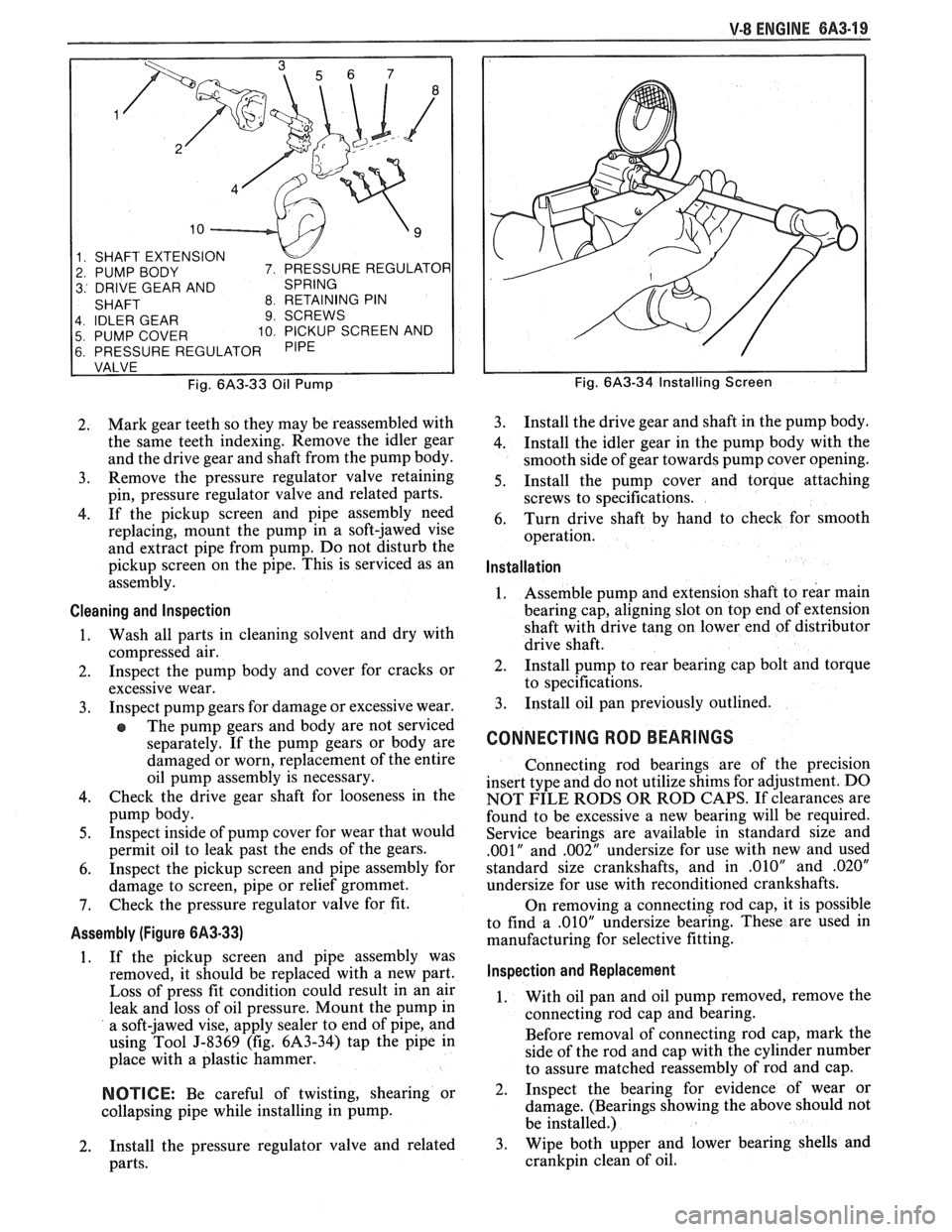
1 SHAFT EXTENSION
2 PUMP BODY
3 DRIVE GEAR AND
4 IDLER GEAR
9 SCREWS
5 PUMP COVER 10 PICKUP SCREEN AND
6 PRESSURE REGULATOR
Fig.
6A3-33 Oil Pump
2. Mark
gear teeth so they may be reassembled with
the same teeth indexing. Remove the idler gear
and the drive gear and shaft from the pump body.
3. Remove
the pressure regulator valve retaining
pin, pressure regulator valve and related parts.
4. If the pickup screen and pipe assembly need
replacing, mount the pump in a soft-jawed vise
and extract pipe from pump. Do not disturb the
pickup screen on the pipe. This is serviced as an
assembly.
Cleaning and lnspection
1. Wash all parts in cleaning solvent and dry with
compressed air.
2. Inspect the pump body and cover for cracks or
excessive wear.
3. Inspect
pump gears for damage or excessive wear.
The pump gears and body are not serviced
separately. If the pump gears or body are
damaged or worn, replacement of the entire
oil pump assembly is necessary.
4. Check the drive gear shaft for looseness in the
pump body.
5. Inspect inside of pump cover for wear that would
permit oil to leak past the ends of the gears.
6. Inspect the pickup screen and pipe assembly for
damage to screen, pipe or relief grommet.
7. Check the pressure regulator valve for fit.
Assembly (Figure 6A3-33)
1. If
the pickup screen and pipe assembly was
removed, it should be replaced with a new part.
Loss of press fit condition could result in an air
leak and loss of oil pressure. Mount the pump in
a soft-jawed vise, apply sealer to end of pipe, and
using Tool J-8369 (fig. 6A3-34) tap the pipe in
place with a plastic hammer.
NOTICE: Be careful of twisting, shearing or
collapsing pipe while installing in pump.
2. Install the
pressure regulator valve and related
parts.
Fig. 6A3-34 Installing Screen
3. Install the drive gear and shaft in the pump body.
4. Install
the idler gear in the pump body with the
smooth side of gear towards pump cover opening.
5. Install the pump cover and torque attaching
screws to specifications.
6. Turn
drive shaft by hand to check for smooth
operation.
Installation
1. Assemble
pump and extension shaft to rear main
bearing cap, aligning slot on top end of extension
shaft with drive tang on lower end of distributor
drive shaft.
2. Install
pump to rear bearing cap bolt and torque
to specifications.
3. Install
oil pan previously outlined.
CONNECTING ROD BEARINGS
Connecting rod bearings are of the precision
insert type and do not utilize shims for adjustment. DO
NOT FILE RODS OR ROD CAPS. If clearances are
found to be excessive a new bearing will be required.
Service bearings are available in standard size and
.001" and ,002" undersize for use with new and used
standard size crankshafts, and in
.010" and .020"
undersize for use with reconditioned crankshafts.
On removing a connecting rod cap, it is possible
to find a
.010" undersize bearing. These are used in
manufacturing for selective fitting.
lnspection and Replacement
1. With
oil pan and oil pump removed, remove the
connecting rod cap and bearing.
Before removal of connecting rod cap, mark the
side of the rod and cap with the cylinder number
to assure matched reassembly of rod and cap.
2. Inspect
the bearing for evidence of wear or
damage. (Bearings showing the above should not
be installed.)
3. Wipe both upper and lower bearing shells and
crankpin clean of oil.
Page 399 of 1825
6A3-20 V-8 ENGINE
PLASTIC GAGE
Fig. 6A3-35 Gaging Plastic On Crankpin-Typical
4. Measure the crankpin for out-of-round or taper
with a micrometer. If not within specifications
replace or recondition the crankshaft. If within
specifications and a new bearing is to be installed,
measure the maximum diameter of the
crankpin
to determine new bearing size required.
5. If within specifications measure new or used
bearing clearances with Plastigage or its
equivalent.
If a bearing is being fitted to an out-of-round
crankpin, be sure to fit to the maximum diameter
of the crankpin. If the bearing is fitted to the
minimum diameter and the
crankpin is
out-of-round .OO 1
" interference between the
bearing and
crankpin will result in rapid bearing
failure.
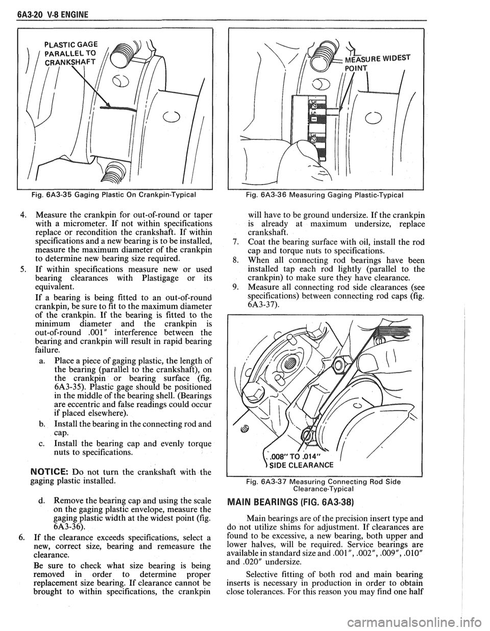
a. Place a piece of gaging plastic, the length of
the bearing (parallel to the crankshaft), on
the
crankpin or bearing surface (fig.
6A3-35). Plastic gage should be positioned
in the middle of the bearing shell. (Bearings
are eccentric and false readings could occur
if placed elsewhere).
b. Install the bearing in the connecting rod and
cap.
c. Install the bearing cap and evenly torque
nuts to specifications.
NOTICE: Do not turn the crankshaft with the
gaging plastic installed.
d. Remove the bearing cap and using the scale
on the gaging plastic envelope, measure the
gaging plastic width at the widest point (fig.
6A3-36).
6. If the clearance exceeds specifications, select a
new, correct size, bearing and remeasure the
clearance.
Be sure to check what size bearing is being
removed in order to determine proper
replacement size bearing. If clearance cannot be
brought to within specifications, the
crankpin
Fig. 6A3-36 Measuring Gaging Plastic-Typical
will have to be ground undersize. If the crankpin
is already at maximum undersize, replace
crankshaft.
7. Coat the bearing surface with oil, install the rod
cap and torque nuts to specifications.
8. When all connecting rod bearings have been
installed tap each rod lightly (parallel to the
crankpin) to make sure they have clearance.
9. Measure all connecting rod side clearances (see
specifications) between connecting rod caps (fig.
6A3-37).
..WS1'TQ.014" 1
s
/
SIDE CLEARANCE
Fig.
6A3-37 Measuring Connecting Rod Side
Clearance-Typical
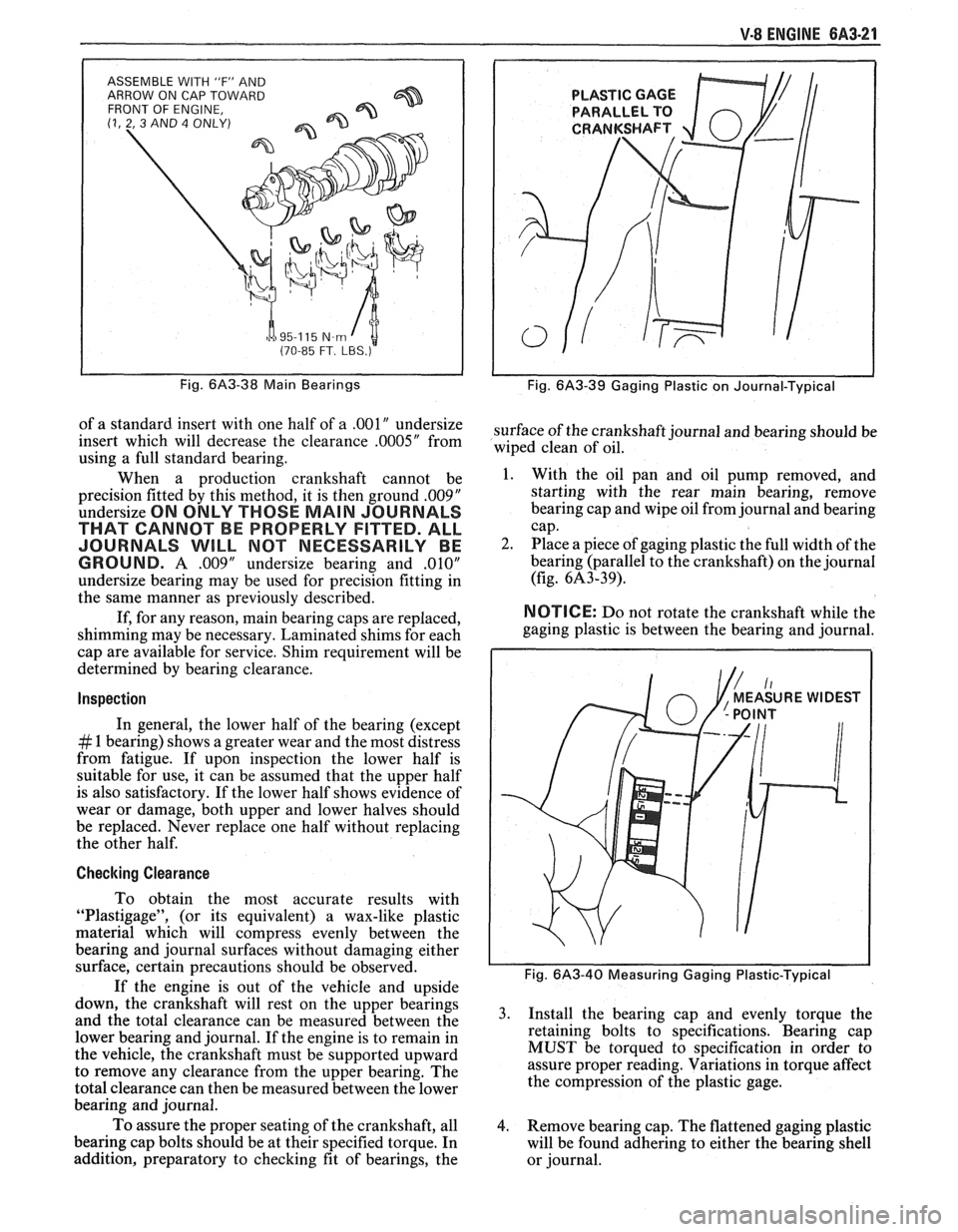
MAIN BEARINGS (FIG. 8A3-38)
Main bearings are of the precision insert type and
do not utilize shims for adjustment. If clearances are
found to be excessive, a new bearing, both upper and
lower halves, will be required. Service bearings are
available in standard size and
,001 ", .002", .009", .01OV
and .020" undersize.
Selective fitting of both rod and main bearing
inserts is necessary in production in order to obtain
close tolerances. For this reason you may find one half
Page 400 of 1825
V-8 ENGINE 6A3-21
ASSEMBLE WITH 'IF" AND
ARROW ON CAP TOWARD
FRONT OF ENGINE,
(1, 2, 3 AND 4 ONLY)
h a 95-1 15 N.m I t (70-85 FT. LBS.)
Fig. 6A3-38 Main Bearings
of a standard insert with one half of a .00lU undersize
insert which will decrease the clearance
.0005" from
using a full standard bearing.
When a production crankshaft cannot be
precision fitted by this method, it is then ground
.00$"
undersize ON ONLY THOSE MAIN JOURNALS
THAT CANNOT BE PROPERLY FITTED. ALL
JOURNALS
WILL MOT NECESSARILY BE
GROUND.
A .009" undersize bearing and ,010"
undersize bearing may be used for precision fitting in
the same manner as previously described.
If, for any reason, main bearing caps are replaced,
shimming may be necessary. Laminated shims for each
cap are available for service. Shim requirement will be
determined by bearing clearance.
Inspection
In general, the lower half of the bearing (except
# 1 bearing) shows a greater wear and the most distress
from fatigue. If upon inspection the lower half is
suitable for use, it can be assumed that the upper half
is also satisfactory. If the lower half shows evidence of
wear or damage, both upper and lower halves should
be replaced. Never replace one half without replacing
the other half.
Checking Clearance
To obtain the most accurate results with
"Plastigage", (or its equivalent) a wax-like plastic
material which will compress evenly between the
bearing and journal surfaces without damaging either
surface, certain precautions should be observed.
If the engine is out of the vehicle and upside
down, the crankshaft will rest on the upper bearings
and the total clearance can be measured between the
lower bearing and journal. If the engine is to remain in
the vehicle, the crankshaft must be supported upward
to remove any clearance from the upper bearing. The
total clearance can then be measured between the lower
bearing and journal.
To assure the proper seating of the crankshaft, all
bearing cap bolts should be at their specified torque. In
addition, preparatory to checking fit of bearings, the
Fig. 6A3-39 Gaging Plastic on Journal-Typical
surface of the crankshaft journal and bearing should be
wiped clean of oil.
1. With the oil pan and oil pump removed, and
starting with the rear main bearing, remove
bearing cap and wipe oil from journal and bearing
cap.
2. Place a piece of gaging plastic the full width of the
bearing (parallel to the crankshaft) on the journal
(fig. 6A3-39).
NOTICE: Do not rotate the crankshaft while the
gaging plastic is between the bearing and journal.
Fig. 6A3-40 Measuring Gaging Plastic-Typical
3. Install the bearing cap and evenly torque the
retaining bolts to specifications. Bearing cap
MUST be torqued to specification in order to
assure proper reading. Variations in torque affect
the compression of the plastic gage.
4. Remove bearing cap. The flattened gaging plastic
will be found adhering to either the bearing shell
or journal.