1988 PONTIAC FIERO check engine
[x] Cancel search: check enginePage 371 of 1825
4. Remove bearing cap. The flattened gaging plastic
will be found adhering to either the bearing shell
or journal.
5. On the edge of gaging plastic envelope, there is a
graduated scale which is correlated in
thousandths of a millimetre. Without removing
the gaging plastic, measure its compressed width
(at the widest point) with the graduations on the
gaging plastic envelope. Normally, main bearing
journals wear evenly and are not out-of-round.
However, if
a bearing is being fitted to an
out-of-round (.025mm max.), be sure to fit to the
maximum diameter of the journal: If the bearing
is fitted to the minimum diameter and the journal
is out-of-round
.025mm, interference between the
bearing and journal will result in rapid bearing
failure. If the flattened gaging plastic tapers
toward the middle or ends, there is a difference
in clearance indicating taper, low spot or other
irregularity of the bearing or journal. Be sure to
measure the journal with a micrometer if the
flattened gaging plastic indicates more than
,025mm difference.
6. If the bearing clearance is within specifications,
the bearing insert is satisfactory. If the clearance
is not within specifications, replace the insert.
Always replace both upper and lower inserts as
a unit.
7. A standard,
.016mm and .032mm undersize
bearing may produce the proper clearance. If not,
it will be necessary to regrind the crankshaft
journal for use with the next undersize bearing.
After selecting new bearing, recheck clearance.
8. Proceed to the next bearing. After all bearings
have been checked rotate the crankshaft to see
that there is no excessive drag.
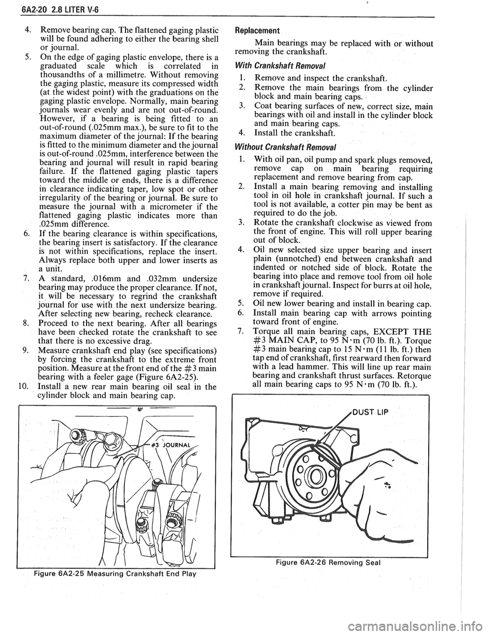
9. Measure crankshaft end play (see specifications)
by forcing the crankshaft to the extreme front
position. Measure at the front end of the
#3 main
bearing with a feeler gage (Figure 6A2-25).
10. Install a new rear main bearing oil seal in the
cylinder block and main bearing cap.
Figure 6A2-25 Measuring Crankshaft End Play
Replacement
Main bearings may be replaced with or without
removing the crankshaft.
With Crankshaft Removal
1. Remove and inspect the crankshaft.
2. Remove the main bearings from the cylinder
block and main bearing caps.
3. Coat bearing surfaces of new, correct size, main
bearings with oil and install in the cylinder block
and main bearing caps.
4. Install the crankshaft.
Without Crankshaft Removal
With oil pan, oil pump and spark plugs removed,
remove cap on main bearing requiring
replacement and remove bearing from cap.
Install a main bearing removing and installing
tool in oil hole in crankshaft journal. If such a
tool is not available, a cotter pin may be bent as
required to do the job.
Rotate the crankshaft clockwise as viewed from
the front of engine. This will roll upper bearing
out of block.
Oil new selected size upper bearing and insert
plain (unnotched) end between crankshaft and
indented or notched side of block. Rotate the
bearing into place and remove tool from oil hole
in crankshaft journal. Inspect for burrs at oil hole,
remove if required.
Oil new lower bearing and install in bearing cap.
Install main bearing cap with arrows pointing
toward front of engine.
Torque all main bearing caps, EXCEPT THE
#3 MAIN CAP, to 95 N.m (70 lb. ft.). Torque
# 3 main bearing cap to 15 N m (1 1 lb. ft.) then
tap end of crankshaft, first rearward then forward
with a lead hammer. This will line up rear main
bearing and crankshaft thrust surfaces.
Retorque
all main bearing caps to 95 N.m (70 Ib. ft.).
1 /DUST LIP
Figure 6A2-26 Removing Seal
Page 372 of 1825
2.8 LITER V-6 6A2-21
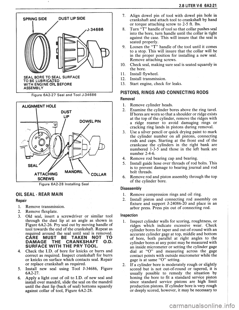
SEAL BORE TO SEAL SURFACE
TO BE LUBRICATED
WlTH ENGINE OK BEFORE I ASSEMBLY
Figure
6A2-27 Seal and Tool J-34686
ALIGNMENT HOLE
DUST
LIP
I SCREWS I
Figure 6A2-28 Installing Seal
OIL SEAL - REAR MAIN
Repair
1. Remove transmission.
2. Remove flexplate.
3. Old
seal, insert a screwdriver or similar tool
through the dust lip at an angle as shown in
Figure
6A2-26. Pry seal out by moving handle of
tool towards the end of the crankshaft. Repeat as
required around the seal until seal is removed.
CARE MUST BE TAKEN NOT TO
DAMAGE THE CRANKSHAFT O.D.
SURFACE
WlTH THE PRY TOOL.
4. Check
the I.D. of bore for knicks or burrs and
correct as required. Inspect crankshaft for burrs
or knicks on surface which contacts seal. Repair
or replace crankshaft as required.
5. Install new seal using Tool J-34686, Figure
6A2-27.
6. Apply a
light coat of oil to I.D. of new seal and
install over mandril, slide the seal on the mandril
until the dust lip (back of seal) bottoms squarely
against collar of tool, Figure
6A2-28.
7. Align dowel pin of tool with dowel pin hole in
crankshaft and attach tool to crankshaft by hand
or torque attaching screw to 2-5 ft. lbs.
8. Turn
"T" handle of tool so that collar pushes seal
into the bore, turn handle until the collar is tight
against the case. This will insure that the seal is
seated properly.
9. Loosen the "T" handle of the tool until it comes
to a stop. This will insure that the collar will be
in the proper position for installing a new seal.
Remove attaching screws.
10. Check seal,
making sure seal is seated squarely in
the bore.
1
1. Install flywheel.
12. Install transmission.
13. Start
engine, check for leaks.
PISTONS, RINGS AND CONNECTING RODS
Removal
1. Remove cylinder heads.
2. Examine the cylinder bores above the ring tavel.
If bores are worn so that a shoulder or ridge exists
at the top of the cylinder, remove the ridges with
a ridge reamer to avoid damaging rings or
cracking ring lands in pistons during removal.
3. Use a silver pencil or quick drying paint to mark
the cylinder number on all pistons, connecting
rods and caps. Starting at the front end of the
crankcase the cylinders in the right bank are
numbered 1-3-5 and those in the left bank are
number 2-4-6.
4. Remove rod bearing
cap and bearing.
5. Install
guide hose over threads of rod bolts. This
is to prevent damage to bearing journal and rod
bolt threads.
6. Remove rod
and piston assembly through the top
of the cylinder bore.
Disassembly
1. Remove compression rings
and oil ring.
2. Install piston and connecting rod assembly on
fixture and support J-24086-20 and place in an
arbor press. Press pin out of connecting rod.
Inspection
1. Inspect cylinder walls for scoring, roughtness, or
ridges which indicate excessive wear. Check
cylinder bores for taper and out-of-round with an
accurate cylinder gage at top, middle and bottom
of bore, both parallel at right angles to the
cylinder bores at any point may be measured with
an inside micrometer or setting the cylinder gage
dial at
"0" and measuring across the gage
contact points with outside micrometer while the
gage is at same
"0" setting.
2. If a cylinder bore is moderately rough or slightly
scored but is not out-of-round or tapered, it is
usually possible to remedy the situation by
honing the bore to fit a standard service piston
since standard service pistons are high limit
production pistons. If cylinder bore is very rough
or deeply scored, however, it may be necessary to
Page 373 of 1825
rebore the cylinder to fit an oversize piston in
order to insure satisfactory results.
3. If cylinder bore is tapered 0. lmm or more or is
out-of-round
O.lmm or more, it is advisable to
rebore for the smallest possible oversize piston
and rings. Below these limits, the cylinder bore
can be trued up with honing.
4. Clean carbon from piston surfaces and under side
of piston heads. Clean carbon from ring grooves
with suitable tool and remove any gum or varnish
from piston skirts with suitable solvent.
5. Carefully examine pistons for
rough or scored
surfaces; cracks in skirt or head; cracked or
broken ring lands; chipped or uneven wearing
pistons would cause rings to seat improperly or
have excessive clearance in ring grooves.
Damaged or faulty pistons should be replaced.
The pistons are cam ground, which means that
the diameter at a right angle to the wrist pin is
greater than the diameter parallel to the wrist pin.
When a piston is checked for size, it must be done
at points 90" to the piston pin. The piston should
be checked (for fitting purposes) in a plane
through the piston pin centerline.
6. Inspect surfaces of wrist pins and check for wear
by measuring worn or unworn surfaces with
micrometers. Occasionally pins will be found
tight due to gum or varnish deposits. This may be
corrected by removing the deposit with a suitable
solvent. If piston bosses are worn out-of-round or
oversize, the piston and pin assembly must be
replaced. Oversize pins are not practical due to
the pin being a press fit in the connecting rod.
Piston pins must fit the piston with an easy finger
push at 70°F (21°C)
(.0065 to .0091mm
clearance).
7. Examine all piston rings for scores, chips or
cracks. Check compression rings for tension by
comparing with new rings. Check gap of
compression rings by placing rings in bore at
bottom of ring travel. Measure gap with feeler
gage. Gap should be between
0.25mm and 0.
50mm. If gaps are excessive (over 0.50mm) it
indicates the rings have worn considerably and
should be replaced. Bore wear should be checked
before rings are replaced,
. l25mm bore wear will
result in
.39mm increase in ring gap.
Assembly
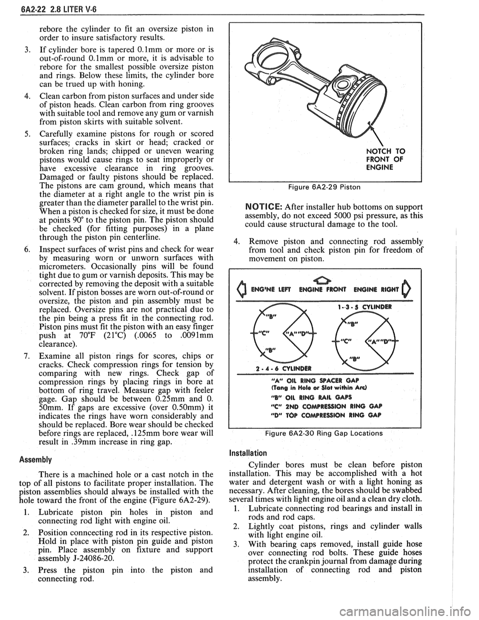
There is a machined hole or a cast notch in the
top of all pistons to facilitate proper installation. The
piston assemblies should always be installed with the
hole toward the front of the engine (Figure
6A2-29).
1. Lubricate piston pin holes in piston and
connecting rod light with engine oil.
2. Position
conncecting rod in its respective piston.
Hold in place with piston pin guide and piston
pin. Place assembly on fixture and support
assembly
J-24086-20.
3. Press the piston pin into the piston and
connecting rod.
NOTCH TO
FRONT OF
ENGINE
Figure 6A2-29 Piston
NOTICE: After installer hub bottoms on support
assembly, do not exceed 5000 psi pressure, as this
could cause structural damage to the tool.
4. Remove piston and connecting rod assembly
from tool and check piston pin for freedom of
movement on piston.
0 Emj@NE Lm ENGINE IRON1 EWINI llWl 0
2 - 1 - 6 CYLINDER
"A" OIL
RING SACER CAP (Tang in Hola w Slot wihin Ad
"B" 011 RING MIL GArs
"C" 1ND COMPRESSION RIM GAB
"DM TOP COAarRESSlON RING GAP
Figure 6A2-30 Ring Gap Locations I
I
Installation I
Cylinder bores must be clean before piston
installation. This may be accomplished with a hot
water and detergent wash or with a light honing as
necessary. After cleaning, the bores should be swabbed
several times with light engine oil and a clean dry cloth.
1. Lubricate connecting rod bearings and install in
rods and rod caps.
2. Lightly coat pistons, rings and cylinder walls
with light engine oil.
3. With bearing caps removed, install guide hose
over connecting rod bolts. These guide hoses
protect the
crankpin journal from damage during
installation of connecting rod and piston
assembly.
Page 376 of 1825
2.8 LITER V-6 6A2-25
Fitting
1. Select rings comparable in size to the piston being
used.
2. Slip
the compression ring in the cylinder bore;
then press the ring down into the cylinder bore
about 6mm above ring travel. Be sure ring is
square with cylinder wall.
3. Measure the space or gap between the ends of the
ring with a feeler gage (Figure
6A2-33).
4. If
the gap between the ends of the ring is below
specifications, remove the ring and try another
for fit.
5. Fit each compression ring to the cylinder in
which it is going to be used.
6. If the pistons have not been cleaned and inspected
as previously outlined, do so.
7. Slip the outer surface of the top and second
compression ring into the respective piston ring
groove and roll the ring entirely around the
groove (Figure
6A2-34). If binding occurs at any
point, the cause should be determined. If there is
a ring groove, remove by dressing with a fine cut
file. If the binding is caused by a distorted ring,
check a new ring.
Installation
1. Install oil ring spacer in groove being sure ends
are butted and not overlapped.
2. Hold
spacer ends butted and install lower steel oil
ring rail.
3. Install upper
steel oil ring rail with gap staggered.
4. Flex
the oil ring assembly to make sure ring is
free. If binding occurs, the cause should be
detemined. If caused by ring groove, remove by
dressing groove with a fine cut file. If binding is
caused by a distorted ring, check a new ring.
5. Install second compression ring. Stagger gap
from other rings.
6. Install top compression ring with gap properly
located.
ENGINE ASSEMBLY
Removal
Disconnect battery.
Remove air cleaner.
Remove hood. Drain radiator.
Remove lower radiator hose.
Remove upper fan shroud.
Remove upper radiator hose and coolant
recovery hose.
Remove transmission cooler lines. Remove radiator.
Remove fan assembly.
Remove heater hoses.
Disconnect carburetor linkage, includes cruise
control detent cable.
Remove vacuum brake booster line.
Remove distributor cap and lay wiring aside.
Disconnect necessary wires and hoses.
Remove power steering pump and lay aside. Raise
vehicle.
Remove exhaust pipes at exhaust manifold.
Remove dust cover.
Remove converter bolts.
Disconnect starter wires.
Remove bell housing bolts.
Remove motor mount through bolts.
Disconnect fuel lines at fuel pump.
Lower vehicle. Support transmission.
Remove
A.I.R./Converter pipes bracket.
Remove engine, include removing wire from
bracket at rear left of engine.
Installation
Position engine assembly in vehicle.
Attach motor mount to engine brackets and
lower engine in place.
Remove engine lifting device.
Remove transmission floor jack.
Raise vehicle on hoist.
Install mount "through" bolts. Torque to
specifications.
Install bell housing bolts. Torque to
specifications.
On vehicles with automatic transmission, install
converter to flywheel attaching bolts. Torque to
specifications.
Install flywheel splash shield of conveter housing
cover as applicable. Torque attaching bolts to
specifications.
Install starter wires.
Connect fuel lines.
Connect exhaust pipe at manifold.
Lower vehicle on hoist.
Reinstall power steering pump, if so equipped.
Connect necessary wires and hoses.
Install radiator and fan shroud and reconnect
radiator and heater hoses.
Fill cooling system.
Fill crankcase with oil. See owner's manual for
specifications.
Install air cleaner.
Install hood.
Connect battery cables.
NOTICE: To avoid possible arcing of battery,
connect positive battery cable first.
22. Start engine, check for leaks and check timing.
CRANKSHAFT
The crankshaft can be removed while the engine
is dissasembled for overhaul, as previously outlined or
without complete disassembly.
Removal
1. With the engine removed from the vehicle,
remove the clutch assembly (if equipped) and
flywheel. Mount engine in stand and clamp
securely.
Page 377 of 1825
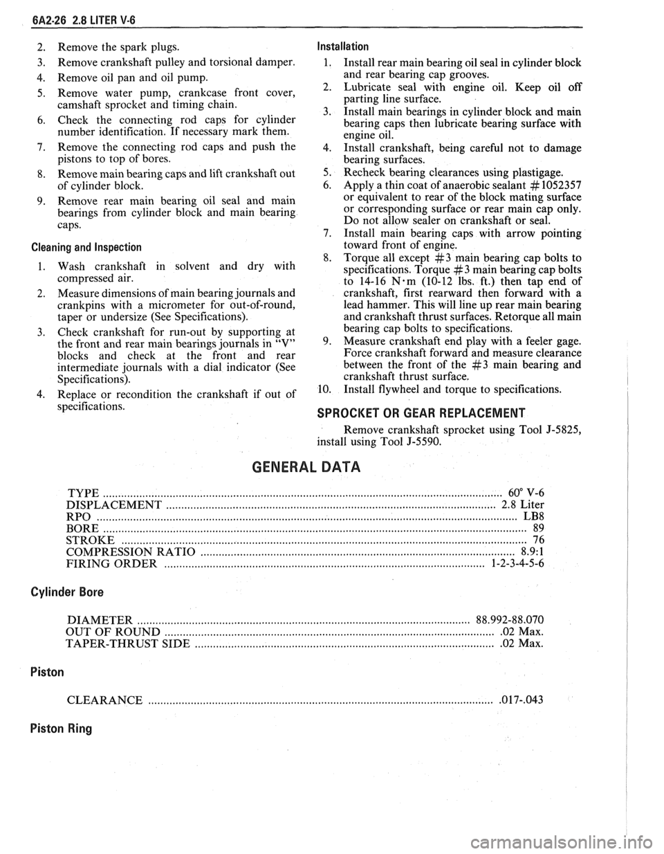
6A2-26 2.8 LITER V-6
2. Remove the spark plugs. Installation
3. Remove
crankshaft pulley and torsional damper. 1. Install rear main bearing oil seal in cylinder block
4. Remove oil pan and oil pump. and
rear bearing cap grooves.
5. Remove water pump, crankcase front cover, 2. Lubricate seal with engine oil. Keep oil off
camshaft sprocket and timing chain. parting
line surface.
3. Install main bearings in cylinder block and main
6. Check the connecting rod caps for cylinder
bearing caps then lubricate bearing surface with
number identification. If necessary mark them.
engine oil.
7. Remove the connecting rod caps and
push the
4. 1n;tall crankshaft, being careful not to damage
pistons to top of bores.
bearing surfaces.
8. Remove main bearing caps and lift crankshaft out 5. Recheck bearing clearances using plastigage.
of cylinder block. 6.
Apply a thin coat of anaerobic sealant
# 1052357
9. Remove rear
main bearing oil seal and main or
equivalent to rear of the block mating surface
bearings from cylinder block and main bearing or corresponding
surface or rear main cap only.
caps. Do
not allow sealer on crankshaft or seal.
7. Install main bearing caps with arrow pointing
Cleaning and Inspection toward front of engine.
8. Torque all except
#3 main bearing cap bolts to
1. Wash crankshaft in solvent and dry with
specifications. Torque
#3 main bearing cap bolts
compressed air. to 14-16
N-m (10-12 lbs. ft.) then tap end of
2. Measure
dimensions of main bearing journals and crankshaft, first rearward then forward with a
crankpins with a micrometer for out-of-round, lead
hammer. This will line up rear main bearing
taper or undersize (See Specifications). and crankshaft
thrust surfaces.
Retorque all main
3. Check
crankshaft for run-out by supporting at bearing
cap bolts to specifications.
the front and rear main bearings journals in "V" 9. Measure crankshaft
end play with a feeler gage.
blocks and check at the front and rear Force crankshaft forward and measure clearance
intermediate journals with a dial indicator (See between the front of the
#3 main bearing and
Specifications). crankshaft thrust surface.
4. Replace or recondition the crankshaft if out of 10.
Install flywheel and torque to specifications.
specifications.
SPROCKET OR GEAR REPLACEMENT
Remove crankshaft sprocket using Tool J-5825,
install using Tool J-5590.
GENERAL DATA
TYPE .................................................................................................................................... 60" V-6
DISPLACEMENT
............................................................................................................. 2.8 Liter
RPO
........................................................................................................................................... LB8
BORE ......................................................................................................................................... 89
STROKE
................................... .... ............................................................................................... 76
COMPRESSION RATIO
....................................................................................................... 8.9: 1
FIRING ORDER
.......................................................................................................... 1-2-3-4-5-6
Cylinder Bore
DIAMETER .............................................................................................................. 88.992-88.070
OUT OF ROUND
............................................................................................................. .02 Max.
TAPER-THRUST SIDE
................................................................................................. .02 Max.
Piston
CLEARANCE .................................................................................................................. .O 17-,043
Piston Ring
Page 381 of 1825
6A3-2 V-8 ENGINE
VALVE TRAIN
A very simple ball pivot-type train is used.
Motion is transmitted from the camshaft through the
hydraulic lifter and push rod to the rocker arm. The
rocker arm pivots on its ball and transmits the
camshaft motion to the valve. The rocker-arm ball is
retained by a nut.
HYDRAULIC VALVE LIFTERS
Hydraulic Valve Lifters are used to keep all parts
of the valve train in constant contact.
The hydraulic lifter assembly consists of: a roller,
the lifter body, which rides in the cylinder block boss,
a plunger, a push rod seat, a metering valve, a plunger
spring, a check ball and spring, a check ball retainer
and a push rod seat retainer.
When the lifter is riding on the low point of the
cam, the plunger spring keeps the plunger and push rod
seat in contact with the push rod.
When the lifter body begins to ride up the cam
lobe, the check ball cuts off the transfer of oil from the
reservoir below the plunger. The plunger and lifter
body then rise as a unit, pushing up the push rod and
opening the valve.
As the lifter body rides down the other side of the
cam, the plunger follows with it until the valve closes.
The lifter body continues to follow the cam to its low
point, but the plunger spring keeps the plunger in
contact with the push rod. The ball check valve will then
move off its seat and the lifter reservoir will
remain full.
INTAKE MANIFOLD
The intake manifold for those engines with
carburetors are made of cast iron or aluminum double
level design for efficient fuel distribution. An Exhaust
Gas Recirculation (EGR) port is also cast into the
manifold for the mixture of exhaust gases with the fuel
air mixture.
The intake manifold for those vehicles equipped
with
PFI is a cast aluminum unit. It centrally supports
a fuel rail with
8 fuel injectors.
EXHAUST MANIFOLDS
Two cast iron exhaust manifolds are used to
direct exhaust gases from the combustion chambers to
the exhaust system. The left hand side manifold
receives a heat shield that is used to route heated air
to the air cleaner. for better fuel vaporization during
warm-up.
COMBUSTION CHAMBERS
Combustion Chambers are cast to insure uniform
shape for all cylinders. Spark plugs are located between
the intake and exhaust valves. The contoured wedge
shape of the combustion chamber minimizes the
possibility of detonation, facilitates breathing and
provides swirling turbulence for smooth, complete
combustion.
ENGINE LUBRICATION
Full pressure lubrication through a full flow oil through drilled passages, to the camshaft and
filter, is furnished by a gear-type oil pump. The crankshaft to lubricate the bearings. The valve lifter oil
distributor, driven by a helical gear on the camshaft,
gallery feeds the valve lifters which, through hollow
drives the oil pump. The main oil gallery feeds oil,
push rods, feed the individually mounted rocker arms.
Page 384 of 1825
V-8 ENGINE BA3-5
ON-VEHICLE SERVICE
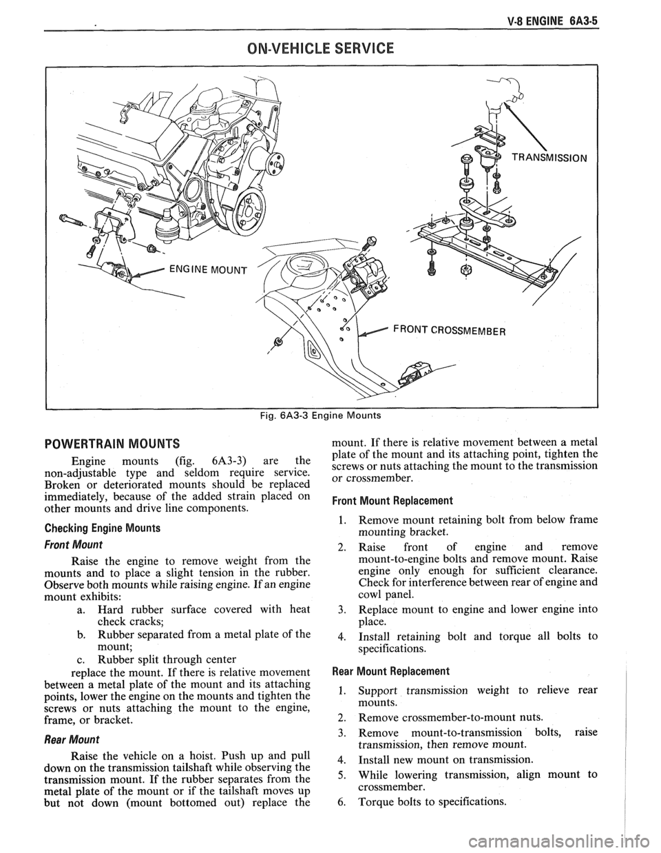
Fig. 6A3-3 Engine Mounts
POWERTRAIN MOUNTS
Engine mounts (fig. 6A3-3) are the
non-adjustable type and seldom require service.
Broken or deteriorated mounts should be replaced
immediately, because of the added strain placed on
other mounts and drive line components.
Checking Engine Mounts
Front Mount
Raise the engine to remove weight from the
mounts and to place a slight tension in the rubber.
Observe both mounts while raising engine. If an engine
mount exhibits:
a. Hard rubber surface covered with heat
check cracks;
b. Rubber separated from a metal plate of the
mount;
c. Rubber split through center
replace the mount. If there is relative movement
between a metal plate of the mount and its attaching
points, lower the engine on the mounts and tighten the
screws or nuts attaching the mount to the engine,
frame, or bracket.
Rear Mount
Raise the vehicle on a hoist. Push up and pull
down on the transmission tailshaft while observing the
transmission mount. If the rubber separates from the
metal plate of the mount or if the tailshaft moves up
but not down (mount bottomed out) replace the mount.
If there is relative movement between a metal
plate of the mount and its attaching point, tighten the
screws or nuts attaching the mount to the transmission
or crossmember.
Front Mount Replacement
1. Remove mount retaining bolt from below frame
mounting bracket.
2. Raise front of engine and remove
mount-to-engine bolts and remove mount. Raise
engine only enough for sufficient clearance.
Check for interference between rear of engine and
cowl panel.
3. Replace mount to engine and lower engine into
place.
4. Install retaining bolt and torque all bolts to
specifications.
Rear Mount Replacement I
1. Support transmission weight to relieve rear
mounts.
2. Remove crossmember-to-mount nuts.
3. Remove mount-to-transmission bolts, raise
transmission, then remove mount.
4. Install new mount on transmission.
5. While lowering transmission, align mount to
crossmember.
6. Torque bolts to specifications.
Page 385 of 1825
6A3-6 V-8 ENGINE
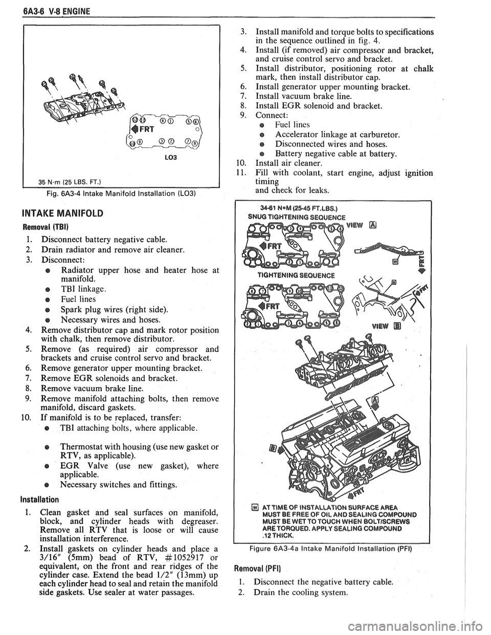
Fig. 6A3-4 Intake Manifold Installation (LO31
INTAKE MANIFOLD
Removal (TBI)
1. Disconnect battery negative cable.
2. Drain radiator and remove air cleaner.
3. Disconnect:
e Radiator upper hose and heater hose at
manifold.
e TBI linkage.
e Fuel lines
Spark plug wires (right side).
e Necessary wires and hoses.
4. Remove distributor cap and mark rotor position
with chalk, then remove distributor.
5. Remove (as required) air compressor and
brackets and cruise control servo and bracket.
6. Remove generator upper mounting bracket.
7. Remove EGR solenoids and bracket.
8. Remove vacuum brake line.
9. Remove manifold attaching bolts, then remove
manifold, discard gaskets.
10. If manifold is to be replaced, transfer:
e TBI attaching bolts, where applicable.
Thermostat with housing (use new gasket or
RTV, as applicable).
EGR Valve (use new gasket), where
applicable.
e Necessary switches and fittings.
lnstallation
1. Clean gasket and seal surfaces on manifold,
block, and cylinder heads with degreaser.
Remove all RTV that is loose or will cause
installation interference.
2. Install gaskets on cylinder heads and place a
3/16" (5mm) bead of RTV, At1052917 or
equivalent, on the front and rear ridges of the
cylinder case. Extend the bead
1/2" (13mm) up
each cylinder head to seal and retain the manifold
side gaskets. Use sealer at water passages. 3.
Install manifold and torque bolts to specifications
in the sequence outlined in
fig. 4.
4. Install (if removed) air compressor and bracket,
and cruise control servo and bracket.
5. Install distributor, positioning rotor at chalk
mark, then install distributor cap.
6. Install generator upper mounting bracket.
7. Install vacuum brake line.
8. Install EGR solenoid and bracket.
9. Connect:
Fuel lines
s Accelerator linkage at carburetor.
@ Disconnected wires and hoses.
Battery negative cable at battery.
10. Install air cleaner.
11. Fill with coolant, start engine, adjust ignition
timing
and check for leaks.
SNUG TIGHTENING SEQUENCE
WEW @
AT TIME OF INSTALUVIBN SURFACE AR- MUST BE FREE OF OIL AND 8ULlNG CQMWUIJD MUST BE Wm TO TOUCH WHEN BBLTISCRWS ARE TORQUED. APPLY SULINO GOMPOLINB
Figure 6A3-4a Intake Manifold Installation (PFI)
Removal (PFI]
1. Disconnect the negative battery cable.
2. Drain the cooling system.