1988 PONTIAC FIERO check engine
[x] Cancel search: check enginePage 135 of 1825

3-10 STEERING, SUSPENSION, TIRES AND WHEELS DIAGNOSIS
Reminder Keeps Operating With Key In Lock
Cylinder, Driver's Door Open Or Closed; Ceases
When Key Is Removed
Inspect
s Door jamb switch on driver's side misadjusted or
inoperative.
e Wire from signal switch to door jamb switch
shorted.
A. This condition indicates the lock cylinder or
the reminder switch is at fault. To verify,
check for continuity at the
"E" and "F"
male column connector contacts, with the
key removed from the lock cylinder. If
continuity exists, the fault is in the column.
B. Insert the key into the lock, then turn the
lock toward the "Start" position. If the
reminder stops when the key is in the
"Run" position or when it is turned past
"Run" toward "Start," the problem is a
sticky lock cylinder actuator.
COLUMN-MOUNTED DIMMER SWITCH
No "Low" or "High" Beam
Inspect
e Loose connector at dimmer switch
e Improper adjustment
e Internally damaged or worn switch. Check the
continuity on the switch at the It. green and at the
tan switch terminals by pushing in the plunger all
the way.
A click should be heard. If there is no
continuity, replace the dimmer switch. If there is
continuity, refer
to'section 8A for electricaldiag-
nosis.
PIVOT AND SWITCH ASSEMBLY
Switch Inoperative: No "Low," "High" and/or
"Wash"
e Loose body-to-switch connector
a Broken or damaged switch
Internally damaged or worn switch. Connect a
new switch without removing the old one. If the
system functions, replace the switch. If the
system doesn't function, refer to Section
8A for
electrical diagnosis.
STEERING GEAR AND PUMP LEAKS
General Procedure
Inspect
s Overfilled reservoir
s Fluid aeration and overflow
e , Hose connections
Verify exact point of leakage Example:
Torsion bar, stub shaft and
adjuster seals are close together; the exact
spot where the system is leaking may not be
clear.
Example: The point from which the fluid is
dripping is not necessarily the point where
the system is leaking; fluid overflowing from
the reservoir, for instance.
e When service is required:
A. Clean leakage area upon disassembly.
B. Replace leaking seal.
C. Check component sealing surfaces for
damage.
D. Reset bolt torque to specifications, where
required.
Some complaints about the power steering system
may be reported as:
A. Fluid leakage on garage floor
B. Fluid leaks visible on steering gear or pump
C. Growling noise, especially when parking or
when engine is cold
D. Loss of power steering when parking
E. Heavy steering effort
When troubleshooting these kinds of complaints,
check for an external leak in the power steering system.
For further diagnosis of leaks, refer to External
Leakage Check in this section.
External Leakage Check
Fig. 12
The purpose of this procedure is to pinpoint the
location of the leak.
In some cases, the leak can easily be located. But,
seepage-type leaks may be more difficult to isolate. To
locate seepage leaks, use the following method.
1. With the engine off, wipe dry the complete power
steering system.
2. Check the fluid level in the pump's reservoir. Add
fluid if necessary.
3. Start the engine, then turn the steering wheel
from stop to stop several times. Do not hold it at
a stop for any length of time, as this can damage
the power steering pump. It is easier if someone
else operates the steering wheel while you search
for the seepage.
4. Find the exact area of the leak and repair leak.
SEAL REPLACEMENT
RECOMMENDATIONS
Lip seals, which seal rotating shafts, require
special treatment. This type of seal is used on the
steering gear and on the drive shaft of the pump. When
there is a leak in one of these areas, always replace the
seal(s), after inspecting and thoroughly cleaning the
sealing surfaces. Replace the shaft only if very severe
pitting is found. If the corrosion in the lip seal contact
zone is slight, clean the surface of the shaft with crocus
cloth. Replace the shaft only if the leakage cannot be
stopped by first smoothing with crocus cloth.
Page 137 of 1825
3-1 2 STEERING, SUSPENSION, TIRES AND WHEELS DIAGNOSIS
POWER STEERlNG SYSTEM "TEST
PROCEDURE
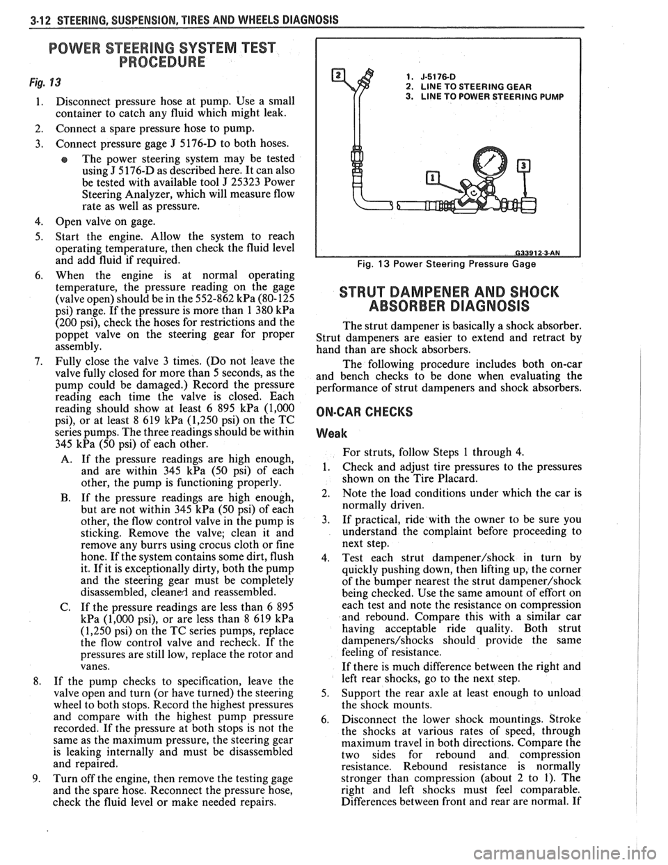
Fig. 13 1. J-5176-D 2. LlNE TO STEERING GEAR
1. Disconnect pressure hose at pump. Use a small 3. LINE TO POWER STEERING PUMP
container to catch any fluid which might leak.
2. Connect a spare pressure hose to pump.
3. Connect pressure gage
J 5176-D
to both hoses.
e The power steering system may be tested
using
J 5 176-D as described here. It can also
be tested with available tool
J 25323 Power
Steering Analyzer, which will measure flow
rate as well as pressure.
4. Open valve on gage.
5. Start the engine. Allow the system to reach
operating temperature, then check the fluid level
and add fluid if required.
6. When the engine is at normal operating
temperature, the pressure reading on the gage
(valve open) should be in the 552-862
kPa (80-125
psi) range. If the pressure is more than 1 380
kPa
(200 psi), check the hoses for restrictions and the
poppet valve on the steering gear for proper
assembly.
7. Fully close the valve 3 times. (Do not leave the
valve fully closed for more than 5 seconds, as the
pump could be damaged.) Record the pressure
reading each time the valve is closed. Each
reading should show at least 6 895
kPa (1,000
psi), or at least 8 619 kPa (1,250 psi) on the TC
series pumps. The three readings should be within
345
kPa (50 psi) of each other.
A. If the pressure readings are high enough,
and are within 345
kPa (50 psi) of each
other, the pump is functioning properly.
B. If the pressure readings are high enough,
but are not within 345
kPa (50 psi) of each
other, the flow control valve in the pump is
sticking. Remove the valve; clean it and
remove any burrs using crocus cloth or fine
hone. If the system contains some dirt, flush
it. If it is exceptionally dirty, both the pump
and the steering gear must be completely
disassembled, cleaned and reassembled.
C. If the pressure readings are less than
6 895
kPa (1,000 psi), or are less than 8 619 kPa
(1,250 psi) on the TC series pumps, replace
the flow control valve and recheck. If the
pressures are still low, replace the rotor and
vanes.
8. If the pump checks to specification, leave the
valve open and turn (or have turned) the steering
wheel to both stops. Record the highest pressures
and compare with the highest pump pressure
recorded. If the pressure at both stops is not the
same as the maximum pressure, the steering gear
is leaking internally and must be disassembled
and repaired.
9. Turn off the engine, then remove the testing gage
and the spare hose. Reconnect the pressure hose,
check the fluid level or make needed repairs.
Fig. 13 Power Steering Pressure Gage
STRUT DAMPENER AND SHOCK
ABSORBER DIAGNOSIS
The strut dampener is basically a shock absorber.
Strut dampeners are easier to extend and retract by
hand than are shock absorbers.
The following procedure includes both on-car
and bench checks to be done when evaluating the
performance of strut dampeners and shock absorbers.
ON-CAR CHECKS
Weak
For struts, follow Steps 1 through 4.
1. Check
and adjust tire pressures to the pressures
shown on the Tire Placard.
2. Note the load conditions under which the car is
normally driven.
3. If practical, ride with the owner to be sure you
understand the complaint before proceeding to
next step.
4. Test each strut
dampener/shock in turn by
quickly pushing down, then lifting up, the corner
of the bumper nearest the strut
dampener/shock
being checked. Use the same amount of effort on
each test and note the resistance on compression
and rebound. Compare this with a similar car
having acceptable ride quality. Both strut
dampeners/shocks should provide the same
feeling of resistance.
If there is much difference between the right and
left rear shocks, go to the next step.
5. Support the rear axle at least enough to unload
the shock mounts.
6. Disconnect the lower shock mountings. Stroke
the shocks at various rates of speed, through
maximum travel in both directions. Compare the
two sides for rebound and compression
resistance. Rebound resistance is normally
stronger than compression (about 2 to 1). The
right and left shocks must feel comparable.
Differences between front and rear are normal. If
Page 194 of 1825
POWER Sf EERING 387-1
SECTION 3B7
POWER STEER NG GEAR AND PUMP
The following notice applies to one or more steps in the assembly procedure of components in this portion
of the manual as indicated at appropriate locations. "See Notice on Page
1 of this Section".
NOTICE: Steering column fasteners are important attaching parts in that they may affect the performance
of vital components and systems, and/or could result in major repair expense. They must be replaced with one
of the same part number or with an equivalent part if replacement becomes necessary. Do not use a replacement
part of lesser quality or substitute design. Torque values must be used as specified during reassembly to assure
proper retention of these parts. For prevailing torque
nut(s) and bolt(s), refer to the "Reuse of Prevailing Torque
Nut(s) and Bolt(s)" chart in Section 10.
CONTENTS
MAINTENANCE AND ADJUSTMENTS
Bleeding Hydraulic System
................................................................................................. 3B7- 1
Fluid Level ......................................................................................................................... 3B7- 1
Power Steering Gear Adj. ..................................................................................................... 3B7- 1
Drive Belt Tension .............................................................................................................. 3B7-2
Hydraulic System Checks .................................................................................................. 3B7-2
Hydraulic System Test ......................................................................................................... 3B7-2
ON-VEHICLE SERVICE
Steering Gear Removal
...................................................................................................... 3B7-3
Pitman Shaft Seal .................................................................................................................. 3B7-3
Pump Removal ..... , ................................................................................................................ 3B7-4
................................................................................................................... Hoses and Pipes 3B7-4
Pump Pulley ....................................................................................................................... 3B7-4
.................................................................................. Pump Brackets/Hoses/Cooling Pipes 3B7-5
........................................................................................ Pump Overhaul .................... ..... 3B7- 12
Gear Overhaul .................................................................................................................... 3B7- 13
SPECIAL TOOLS ............................................................................................................ 3B7-17 ......................... .......................................................... GENERAL SPECIFICATIONS .. 3B7- 18
MAlNKNANGE AND ADJUSTMENTS
BLEEDING HYDRAULIC SYSTEM
Fill fluid reservoir to proper level and let remain
undisturbed for at least two minutes.
Start engine and run momentarily.
Shut engine off to add fluid.
Repeat above procedure until fluid level remains
constant after running engine.
Raise front end of vehicle so that wheels are off
the ground.
Start engine and increase engine speed to
approximately
1500 rpm.
Turn the wheels (off ground) right and left,
lightly contacting the wheel stops.
Lower the car and turn wheels right and left on
the ground.
Shut engine off, check fluid level and refill as
required.
If fluid is extremely foamy, allow vehicle to stand
a few minutes with engine off while you run
through the following:
a. Check belt
tightness and check for a bent or
loose pulley. (Pulley should not wobble with
engine running.) b.
Check
to make sure hoses are not touching
any other parts of the car, particularly sheet
metal and exhaust manifold.
c. Check fluid
level, filling to proper level if
necessary. Air in the fluid is the most
frequent cause of objectionable pump noise.
d. When air is present, bleed system as
described in operations 1 through 10. If the
pump will not bleed after a few trials,
proceed as outlined under Hydraulic
System Checks. FLUID LEVEL
1. Check fluid level in the reservoir by checking the
dip stick when fluid is at operating temperature.
2. Fill, if necessary, to proper level with GM Power
Steering Fluid, or equivalent.
POWER STEERING GEAR ADJUSTMENTS
Adjustment of the power steering gear in the
vehicle is discouraged because of the difficulty involved
in adjusting the worm thrust bearing preload and the
confusing effects of the hydraulic fluid in the gear. The
steering gear adjustment is made only as a correction
and not as a required periodic adjustment.
Page 195 of 1825
387-2 POWER STEERING
The effect of improperly adjusted worm thrust
bearings or an improperly adjusted over-center preload
could cause a handling stability complaint.
To properly adjust the power steering gear, the
assembly MUST be removed from the vehicle and
adjustments performed as outlined.
For removal of the power steering gear assembly
see "Power Steering Gear".
DRIVE BELT TENSION
All drive belt tension specifications can be found
in the Engine Cooling Section 6B.
When adjusting a power steering pump belt,
never pry against the pump reservoir or pull against the
filler neck. Two systems are used for belt adjustment.
On some
models, the pump is loosened from the
bracket and moved outward to increase the tension. On
other models, a half-inch square drive hole is located
in the bracket, and this hole is used to rotate the
pump-and-bracket assembly outward to increase belt
tension.
Place belt tension gage, J-23600 or equivalent
midway between the pulleys on drive belt being
checked.
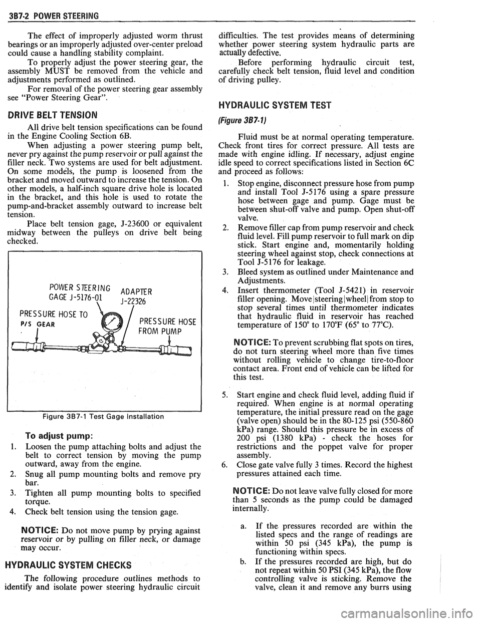
POWER SKERING ADAPER GAGE J-5176-01 J-22326
PRESSURE HOSE TO
P/S GEAR PRESSURE HOSE
Figure 387-1 Test Gage Installation
To adjust pump:
1.
Loosen the pump attaching bolts and adjust the
belt to correct tension by moving the pump
outward, away from the engine.
2. Snug all pump mounting bolts and remove pry
bar.
3. Tighten all pump mounting bolts to specified
torque.
4. Check belt tension using the tension gage.
NOTICE: Do not move pump by prying against
reservoir or by pulling on filler neck, or damage
may occur.
HYDRAULIC SYSTEM CHECKS
The following procedure outlines methods to
identify and isolate power steering hydraulic circuit difficulties.
The test provides means of determining
whether power steering system hydraulic parts are
actually
defective.
Before performing hydraulic circuit test,
carefully check belt tension, fluid level and condition
of driving pulley.
HYDRAULIC SYSTEM TEST
(Figure 387- lj
Fluid must be at normal operating temperature.
Check front tires for correct pressure. All tests are
made with engine idling. If necessary, adjust engine
idle speed to correct specifications listed in Section 6C
and proceed as follows:
1. Stop engine, disconnect pressure hose from pump
and install Tool
5-5176 using a spare pressure
hose between gage and pump. Gage must be
between shut-off valve and pump. Open shut-off
valve.
2. Remove filler cap from pump reservoir and check
fluid level. Fill pump reservoir to full mark on dip
stick. Start engine and, momentarily holding
steering wheel against stop, check connections at
Tool J-5 176 for leakage.
3. Bleed system as outlined under Maintenance and
Adjustments.
4. Insert thermometer (Tool J-5421) in reservoir
filler opening. Move
/steering (wheel/ from stop to
stop several times until thermometer indicates
that hydraulic fluid in reservoir has reached
temperature of
150" to 170°F (65" to 77°C).
N OTI G E: To prevent scrubbing flat spots on tires,
do not turn steering wheel more than five times
without rolling vehicle to change tire-to-floor
contact area. Front end of vehicle can be lifted for
this test.
5. Start engine and check fluid level, adding fluid if
required. When engine is at normal operating
temperature, the initial pressure read on the gage
(valve open) should be in the 80-125 psi (550-860
kPa) range. Should this pressure be in excess of
200 psi (1380
kPa) - check the hoses for
restrictions and the poppet valve for proper
assembly.
6. Close gate valve fully
3 times. Record the highest
pressures attained each time.
N OTI C E: Do not leave valve fully closed for more
than
5 seconds as the pump could be damaged
internally.
a. If
the pressures recorded are within the
listed specs and the range of readings are
within 50 psi (345
kPa), the pump is
functioning within specs.
b. If the pressures recorded are high, but do
not repeat within 50 PSI (345
kPa), the flow
controlling valve is sticking. Remove the
valve, clean it and remove any burrs using
Page 196 of 1825
POWER STEERING 387-3
crocus cloth or fine hone. If the system 4. If the pump checks within specifications, leave
contains some dirt, flush it. If it is the valve open and turn (or have turned) the
exceptionally dirty, both the pump and the steering wheel into both corners. Record the
gear must be completely disassembled, highest pressures and compare with the
cleaned, flushed and reassembled before maximum pump pressure recorded. If this
further usage. pressure cannot be built in either (or one) side of
- the gear, the gear is leaking internally and must
c. If
the pressures recorded are constant, but
be disassembled and repaired. See "Unit Repair"
more than
100 PSI (690 kPa), below the
at the end of this section.
spec.9 rep1ace the flow 8. Shut off engine, remove testing gage, spare hose,
valve and recheck. If the pressures are still
low, replace the rotating group in the pump. reconnect pressure hose, check fluid
level and/or
make needed repairs.
ON-VEHICLE SERVICE
POWER STEERING GEAR
(Figure 387-2)
Removal
Place drain pan below, then disconnect pressure
and return hoses from the steering gear housing. Cap
both hoses and steering gear outlets to prevent foreign
material from entering the system. After service is
performed and steering gear is installed, connect the
pressure and return hoses to the steering gear housing.
Install coupling shield. Bleed system as outlined under
"Maintenance and Adjustments".
1. Disconnect battery ground cable and remove
coupling shield.
2. Remove retaining nuts, lock washers, and bolts
at steering coupling to steering shaft flange.
3. Remove pitman arm nut and washer from
pitman shaft and mark relation of arm position to
shaft.
4. Remove pitman arm with Tool J-6632.
5.
Remove screws securing steering gear to frame
and remove gear from vehicle.
Installation
NOTICE: See NOTICE on page 1 of this section
regarding the fasteners referred to in steps 1,2 and
3.
1. Place gear into position so that steering coupling
mounts properly to flanged end of steering shaft.
Secure gear to frame with washers and bolts.
Torque all gear to frame fasteners.
NOTICE: Be sure the coupling is bottomed on the
wormshaft so that the coupling bolt passes
through the undercut on the wormshaft, or
damage may occur.
2. Secure steering coupling to flanged end of
steering column with lock washers, and nuts.
Maintain coupling adjustments shown in Section
3B5, under "Installation of Steering Column".
Torque nuts.
3. Install pitman arm, aligning marks made during
removal. Install washer and retaining nut.
Torque nut.
4. Install coupling shield and connect battery
ground cable.
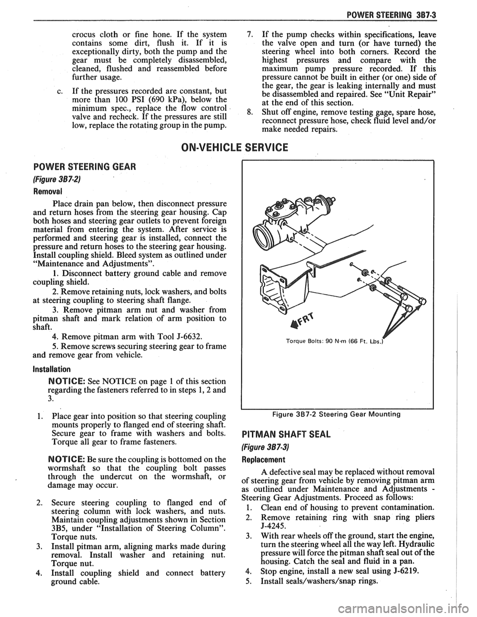
Torque Bolts: 90 Nm (66 Ft. ~bs.r
Figure 3B7-2 Steering Gear Mounting
PITMAN SHAFT SEAL
(Figure 387-3)
Replacement
A defective seal may be replaced without removal
of steering gear from vehicle by removing
pitman arm
as outlined under Maintenance and Adjustments
-
Steering Gear Adjustments. Proceed as follows:
1. Clean end of housing to prevent contamination.
2. Remove retaining
ring with snap ring pliers
J-4245.
3. With rear wheels off the ground, start the engine,
turn the steering wheel all the way left. Hydraulic
pressure will force the
pitman shaft seal out of the
housing. Catch the seal and fluid in a pan.
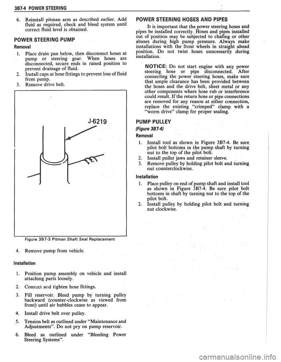
4. Stop engine, install a new seal using 5-6219.
5. Install seals/washers/snap rings.
Page 197 of 1825
3B7-4 POWER STEERING
6. Reinstall pitman arm as described earlier, Add
fluid as required, check and bleed system until
correct fluid level is obtained.
POWER STEERING PUMP
Removal
1. Place drain pan below, then disconnect hoses at
pump or steering gear. When hoses are
disconnected, secure ends in raised position to
prevent drainage of fluid.
2. Install caps at hose fittings to prevent loss of fluid
from pump.
3. Remove drive belt.
Figure 3B7-3 Pitman Shaft Seal Replacement
4. Remove pump from vehicle.
Installation
1. Position pump assembly on vehicle and install
attaching parts loosely.
2. Gonl7.zct and tighten hose fittings.
3. Fill reservoir. Bleed pump by turning pulley
backward (counter-clockwise as viewed from
front) until air bubbles cease to appear.
4. Install drive belt over pulley.
5. Tension belt as outlined under "Maintenance and
Adjustments". Do not pry on pump reservoir.
6. Bleed as outlined under "Bleeding Power
Steering Systems".
POWER STEERING HOSES AND PIPES
It is important that the power steering hoses and
pipes be installed correctly. Hoses and pipes installed
out of position may be subjected to chafing or other
abuses during high pump pressure. Always make
installations with the front wheels in straight ahead
position. Do not twist hoses unncessarily during
installation.
NOTICE: Do not start engine with any power
steering hose or pipe disconnected. After
connecting the power steering hoses, make sure
that ample clearance has been provided between
the hoses and the drive belt, sheet metal or any
other components where hose rub or interference
could result. If the return hose or pipe connections
are removed for any reason at either connection,
replace the existing "crimped" clamp with a
"worm drive" clamp for proper sealing.
PUMP PULLEY
(Figure 38 7-41
Removal
1. Install tool as shown in Figure 3B7-4. Be sure
pilot bolt bottoms in the pump shaft by turning
nut to the top of the pilot bolt.
2. Install puller jaws and retainer sleeve.
3. Remove pulley by holding pilot bolt and turning
nut counterclockwise.
Installation
1. Place
pulley on end of pump shaft and install tool
as shown in Figure 3B7-4. Be sure pilot bolt
bottoms in shaft by turning nut to the top of the
pilot bolt.
2. Install pulley by holding pilot bolt and turning
nut clockwise.
Page 239 of 1825
3E-8 TIRES AND WHEELS
nearest the valve stem, and a 1/2 ounce balance weight
should be added 180" opposite the locking nut on the
wheel's inboard side.
When rotating tires, always re-install the locking
nut nearest the tire valve stem so that it remains
opposite the 1/2 ounce balance weight. This procedure
will improve the on-car wheel balance by compensating
for the heavy locking wheel nut.
Off-Car Balancing
Most electronic off-car balancers are more
accurate than the on-car spin balancers. They are easy
to use and give a dynamic (two plane) balance.
Although they do not correct for drum or rotor
unbalance as does on-car spin balancing, this is
overcome by their accuracy (usually to within 1/8
ounce). When balancing off-car, the wheel should
locate on the balancer with a cone through the back
side of the center pilot hole (not by the wheel stud
holes).
On-Car Balancing
When needed, on-car balancing will help correct
vibrations due to brake drum, rotor, and wheel cover
imbalance.
When balancing on car, do not remove the
balance weights from the off-car dynamic balance. If
more than one ounce of additional weight is required,
it should be split between the inner and outer rim
flange.
NOTICE: The driven tire and wheel assemblies
should be spun using the engine. Limit speed as
stated in the following Caution.
CAUTION: Do not spin the drive
wheels faster than
35 mph (55 km/h)
as indicated by the speedometer. This
limit is necessary because the
speedometer indicates only one-half
of the actual wheel speed when one
drive wheel is spinning and the other
drive wheel is stopped. Personal injury
and damage may result from high
speed spinning.
CAUTION: On cars equipped with
limited slip rear axles, do not attempt
to balance a tire on a
drive wheel with
the other drive wheel on the ground.
The car may drive through this wheel
and cause the car to move
unexpectedly, resulting in personal
injury and property damage.
To distinguish between standard rear axle and
limited slip, raise rear of car so both tires are clear of
ground. With the transmission in park (in gear with
manual transmission), attempt to turn one wheel by
hand. If the wheel can be turned, it is a standard rear
axle; if the wheel cannot be turned, it is a limited slip
rear axle. Also, check for Limited Slip
(G80) on Service
Parts Identification label.
Wheel Weights
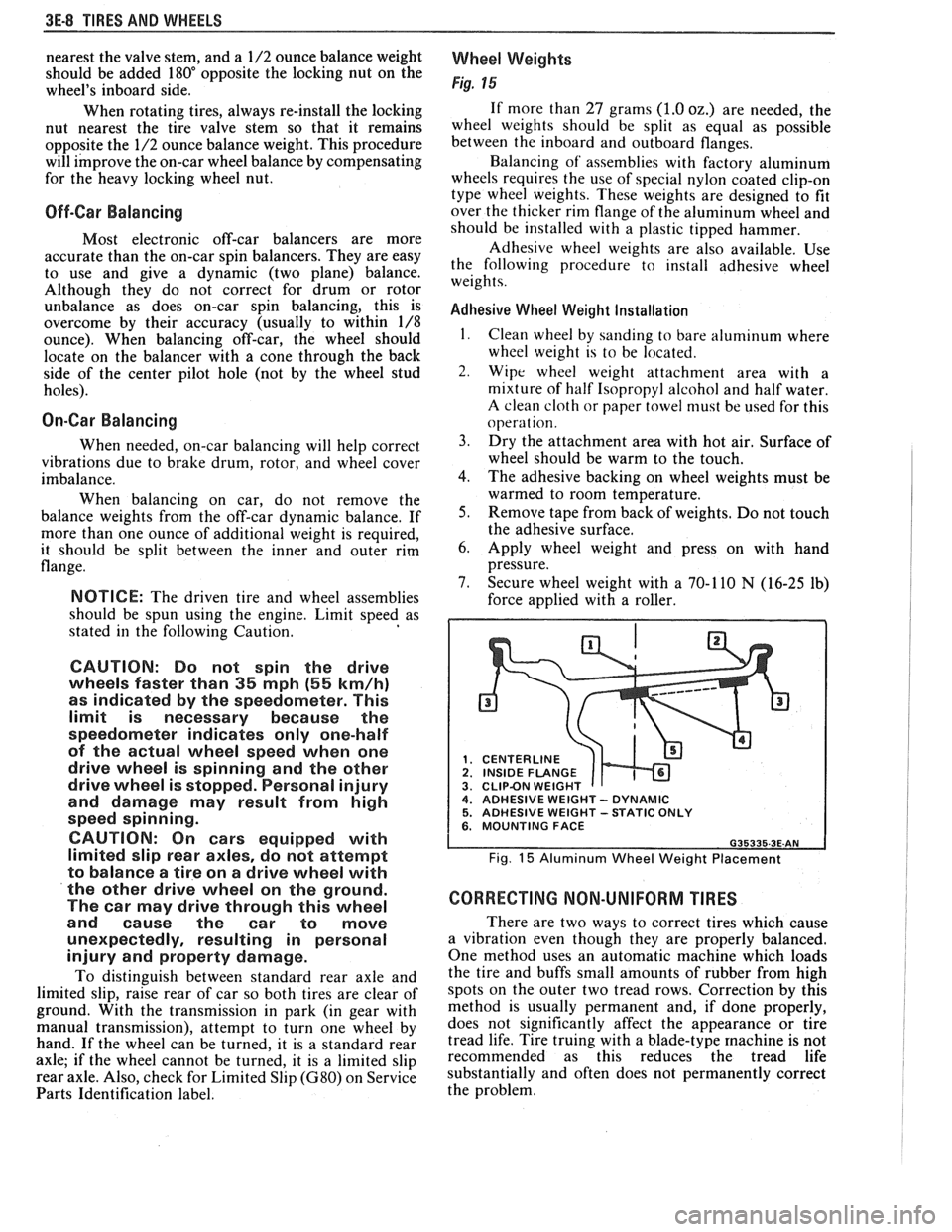
Fig. 15
If more than 27 grams (1.0 oz.) are needed, the
wheel weights should be split as equal as possible
between the inboard and outboard flanges.
Balancing of' assemblies with factory aluminum
wheels requires the use of special nylon coated clip-on
type wheel weights. These weights are designed to fit
over the thicker rim flange of the aluminum wheel and
should be installed with a plastic tipped hammer.
Adhesive wheel weights are also available. Use
the following procedure to install adhesive wheel
weights.
Adhesive Wheel Weight Installation
1. Clean wheel by sanding to bare aluminum where
wheel weight is to be located.
2. Wipe wheel weight attachment area with a
mixture of half Isopropyl alcohol and half water.
A clean cloth or paper towel niust be used for this
operat ion.
3. Dry the attachment area with hot air. Surface of
wheel should be warm to the touch.
4. The adhesive backing on wheel weights must be
warmed to room temperature.
5. Remove tape from back of weights. Do not touch
the adhesive surface.
6. Apply wheel weight and press on with hand
pressure.
7. Secure wheel weight with a 70-1 10
N (16-25 lb)
force applied with a roller.
CENTERLINE
1 INSIDE FLANGE CLIPBN WEIGHT 4. ADHESIVE WEIGHT - DYNAMIC 5. ADHESIVE WEIGHT -STATIC ONLY 6. MOUNTING FACE
Fig. 15 Aluminum Wheel Weight Placement
CORRECTING NON-UNIFORM TIRES
There are two ways to correct tires which cause
a vibration even though they are properly balanced.
One method uses an automatic machine which loads
the tire and buffs small amounts of rubber from high
spots on the outer two tread rows. Correction by this
method is usually permanent and, if done properly,
does not significantly affect the appearance or tire
tread life. Tire truing with a blade-type
machine is not
recommended as this reduces the tread life
substantially and often does not permanently correct
the problem.
Page 244 of 1825
PROPELLER SHAFT $A-3
B. If companion flange run-out is over 0.15mm (.006
in.) but less than 0.28mm (.011 in.) and balance
weight is at or near low point of companion flange
run-out, no further action is required.
If balance weight is not at or near low point of
companion flange run-out, remove weight.
6. If companion flange run-out is over 0.28mm (.011
in.), but no greater than 0.38mm (.015 in.) and
balance weight is at or near low point of
companion flange run-out, no further action is
required.
If balance weight is not at or near low point of
companion flange
runout, remove weight and
reindex companion flange until run-out is 0.25
mm
(.010 in.) or less.
If impossible to achieve
0.25mm (.010 in.) or less
run-out, install a new companion flange and
recheck for
0.25mm (.010 in.) or less run-out.
Service replacement companion flanges are not
equipped with balance weights and no weights
should be added.
UNIVERSAL JOINT ANGLE MEASUREMENT
When torque is transmitted through any ordinary
universal joint, the driven yoke fluctuates slightly in
speed. In other words, although the driving yoke
rotates at a constant speed, the driven yoke speeds up
and slows down twice per revolution. This flucutation
of the driven yoke is in direct proportion to the angle
through which the universal joint is operating; the
greater the angle, the greater the fluctuation.
Whenever two universal joints are used, this
fluctuation effect can be eliminated by staggering the
joints so that the two driving yokes are 90 degrees apart
provided the two joints are transmitting torque
through the same angle.
Therefore, when two universal joints are used, the
angles through which they operate must be very nearly the
same. This allows the alternate acceleration and decelera-
tion of one joint to be offset by the alternate acceleration
and deceleration of the second joint. When the two joints
do not run at approximately the same angle, operation is
rough and an objectionable vibration is produced.
The actual optimum angles desired must take into
consideration the effects of various passenger loadings
and rear axle windup during acceleration; therefore, it
is unlikely that the front and rear universal joint angles
will be found to be the same in actual practice.
In addition, universal joints are designed to
operate safely and efficiently within certain angles. If
the designed angle is exceeded, the joint may be broken
or otherwise damaged.
The front universal joint angle is actually the
angle between the engine-transmission centerline and
the propeller shaft centerline. This angle is determined
by the design of the frame assembly and may be altered
by adding or removing shims between the transmission
and the transmission mount.
Adding one shim at the transmission mount will
decrease the transmission universal joint angle by
1/2"
and increase differential universal joint angle by 1/4".
If one shim is removed the tranmission angle will
increase
1/2" and decrease differential angle I/@. The
production transmission mount bolt is an
M10-1.5 x 35
mm. When installing two or more shims, an
M10-1.5
x 50 mm bolt must be used.
All complaints of propeller shaft vibrations
should be accompanied by rear trim height
measurements at curb weight. An incorrect trim height
may cause some vibration. If vibration is severe
enough, removal or installation of spring shims may be
required. If any irregular roughness or vibration is
detectable in the drive line, the front and rear universal
joint angles should be checked. Should the vehicle
become involved in a severe rear end collision, or
should the rear axle carrier be replaced, the rear
universal joint angle should be checked and control
arms should be replaced if necessary.
Figure 4A-6
This method can be used with the vehicle over a
pit or on a drive-on platform hoist, as long as the
vehicle is at curb weight with a full tank of gasoline.
Bounce vehicle up and down to assure curb height.
Before universal joint angles can be checked, the
measurements specified (the distance between the top
of the axle tube and the bottom of the frame) must be
met. To insure an accurate measurement, weight may
have to be added to the vehicle to reach these
specifications.
Readings should be taken at the following
locations in the following manner.
Angle Measurement at Rear Universal Joint
Figures 4A-7 and 4A-8
1. Place inclinometer J 23498-A on rear propeller
shaft bearing cap. Center bubble in sight glass and
record measurement. Bearing cap must be straight
up and down and free of dirt or other foreign mate-
rial to obtain an accurate measurement.
2. Rotate propeller shaft 90 degrees and place
inclinometer on the companion flange bearing
cap. Center bubble in sight glass and record
measurement.
3. Subtract smaller figure from larger figure to
obtain existing rear universal joint angle.
Angle Measurement at Front Universal Joint
Figures 4A.9 and 4A- 10
1. Place inclinometer on front propeller shaft
bearing cap. Center bubble in sight and record
measurement.
2. Rotate propeller shaft 90 degrees and place
inclinometer on the slip yoke bearing cap. Center
bubble on sight glass and record measurement.
3. Substract smaller figure from larger figure
lo
obtain existing front universal joint angle.