1988 PONTIAC FIERO brake
[x] Cancel search: brakePage 942 of 1825
DWlVEABlLlTV AND EMISSIONS 5.01, QVIN F) & 5.71 (VIN 8) 6E3-C8-1
TRANSMISSION CONVERTER CLUTCH (KC) SYSTEM
AND MANUAL "TRANSMISSION SHlFT LBGH"O"=Ob ONLY
CONTENTS
................ GENERAL DESCRIPTION C8-1 DIAGNOSIS ....................... .. C8-1
........ PURPOSE ......................... CS-1 SHIFT LIGHT (MIT) DESCRIPTION C8-1
....................... OPERATION C8-1 DIAGNOSIS ......................... CS-1
OM-CAR SERVICE ..................... C8-1
GENERAL DESCRIPTION
PURPOSE
The transmission converter clutch (TCC) system
uses
a solenoid operated valve in the automatic
transmission to couple the engine flywheel to the
output shaft of the transmission thru the torque
converter. This reduces the slippage losses in the
converter, which increases fuel economy.
OPERATION
For the converter clutch to apply, two conditions
must be met:
e Internal transmission fluid pressure must be
correct. For information on internal transmission
operation, see Section
"7A". This section will
cover only the electrical operation of the TCC
system.
@ The ECM grounds a switch internally to turn
"ON" a solenoid in the transmission. This moves a
check ball, which will allow the converter clutch
to apply, if the hydraulic pressure is correct, as
described above.
The ECM controls the TCC apply solenoid by
looking at several sensors:
@ Speedo Buffer Sensor (also called Vehicle Speed
Sensor
(VSS) Speed must be above a certain value
before the clutch can apply.
@ Coolant Temperature Sensor Engine must be
warmed
LIP before clutch can apply about 65" C
(149°F).
Throttle Position Sensor (TPS) After the
converter clutch applies, the ECM uses the
information
from the TPS to release the clutch
when the car is accelerating or decelerating at
a
certain rate.
The brake switch
is also part of the 'I'CC circuit as
it will remove battery voltage to the
'FCC solenoid
when the brake pedal is depressed.
@ Gear Select Switch The 4th gear switch is used to
send a signal to the ECM telling it when the
transmission is in 4th
gear
The ECM uses this information to vary the conditions
under which the clutch applies or releases. However,
the transmission does not have to be in fourth gear in
order for the ECM to turn the clutch "ON".
If the converter clutch is applied at all times, the
engine will stall immediately, just as in a manual
transmission with the clutch applied.
If the converter
clutch does not apply, fuel
ecomony may be lower than expected. If the vehicle
speed sensor fails, the TCC will not apply. If the 4th
gear switch does not operate, the TCC may not apply
at the right time.
DIAGNOSIS
The diagnosis of the TCC system is covered in
CHART C-$A. If the ECM detects a problem in the
system, a Code 24 should set. In this case, see Code 24
CHART.
SHIFT LIGHT (MR) DESCRIPTION
The purpose of the shift light is to provide a
display which indicates the optimum fuel economy
point for up shifting the manual transmission based
on engine speed and load. The display is
a lamp on the
instrument panel. Activation
of the ECM driver turns
the lamp "ON".
DIAGNOSIS
The shift light circuit can be checked using
CEIAR'I' C-8B.
ON-CAR SERVICE
See Section "8B" if the shift light bulb needs
replacement.
See Section
"GE" to repair wiring problem.
@ See Section "C- 1" if ECM is to be replaced.
Page 964 of 1825
DRIVEABILITY AND EMISSIONS - FUEL INJECTION 6E-3
VEHICLE EMISSION CONTROL INFORMATION
MBEL
The Vehicle Emission Control Information label
(Figure
1) contains important emission specifications
and setting procedures. In the upper left corner is
exhaust emission information which identifies the
year, the manufacturing division of the engine, the
displacement in liters of the engine, the class of
vehicle and type of fuel metering. Also there is an
illustrated emission component and vacuum hose
schematic. A similar label is located in the engine
compartment of every General Motors Corporation
vehicle. If the label has been removed, it can be
ordered from the parts division.
(WDDGM)
INTRODUCTION
Electronic Engine Control
Each engine has an electronic engine control
module
(ECM) to control the fuel system. The ECM
varies the
airlfuel ratio by controlling the fuel flow
through the
injectorb).
In addition, the ECM controls the ignition timing
as well as the fuel pump and other systems.
It is important to review the component sections
and wiring diagrams in Section
"6E2" and "6E3" for a
specific engine, to determine what is controlled by the
ECM and what systems are
non-ECM controlled.
What This Section Contains
Each General Motors engine has system controls
to reduce exhaust emissions while maintaining good
driveability and fuel economy. This section explains:
@ Wow to use the Driveability and Emission
Sections
"6E2" for TBI, and "6E3" for Port
Fuel engines.
A brief description of systems used to control
fuel and emissions.
@ Abbreviations that are used in "Driveability
and Emissions".
@ Wiring harness service information for
harnesses used with the ECM.
@ Special tools used to diagnosis and repair a
system. Before
checking the system, observe the following:
Blocking Drive Wheels
The vehicle drive wheels always should be
blocked, and parking brake firmly set, while checking
the system.
Cold Oxygen Sensor
On some engines, the oxygen sensor will cool off
after only a short period of operation at idle. This will
put the system into "Open Loop". To restore "Closed
Loop" operation, run the engine at part throttle and
accelerate from idle to part throttle a few times until
the system goes "Closed Loop".
VlSUAUPHYSlCAL UNDERHOOD
INSPE6"rON
This can often lead to fixing a problem without further
steps. Inspect all vacuum hoses for correct routing,
pinches, cuts, or disconnects. Be sure to inspect hoses
that are difficult to see beneath the air cleaner,
compressor, generator, etc. Inspect all the wires in the
engine compartment for correct and good connections,
burned or chafed spots, pinched wires, or contact with
sharp edges or hot exhaust manifolds. This
visual/physical inspection is very important. It must ,
be done carefully and thoroughly.
BASIC KNOWLEDGE REQUIRED
Before using this section of the service manual,
there are some areas that you should be familiar with.
Without this basic knowledge, you will have trouble
using the diagnostic procedures contained in this
section.
Basic Electric Circuits
You should understand the basic theory of
electricity, and know the meaning of voltage, amps,
ALL NEW GENERAL MOTORS VEHICLES ARE CERTIFIED BY THE UNITED STATES
ENVIRONMENTAL PROTECTION
AGENCY AS CONFORMING TO THE REQUIREMENTS OF THE
REGULATIONS
FOR THE CONTROL OF AIR POLLUTION FROM NEW MOTOR VEHICLES. THlS
CERTIFICATION IS CONTINGENT OM CERTAIN ADJUSTMENTS BEING SET TO FACTORY
STANDARDS. IN MOST CASES, THESE ADJUSTMENT
POINTS EITHER HAVE BEEN
PERMANENTLY SEALED
AND/OR MADE INACCESSIBLE TO PREVENT INDISCRIMINATE OR
ROUTINE ADJUSTMENT IN THE FIELD. FOR
THlS REASON, "TI- FACTORY PROCEDURE FOR
TEMPORARILY REMOVING PLUGS, CAPS, ETC., FOR PURPOSES OF SERVICING THE PRODUCT,
MUST BE STRICTLY FOLLOWED AND, WHEREVER PRACTICABLE, RETURNED
TO WE
ORIGINAL INTENWF THE DESIGN.
Page 990 of 1825
HYDRAULIC DIAGNOSIS 700.R4-1
SECTION 700-R4
AUTOMAT C TRANSM
CONTENTS
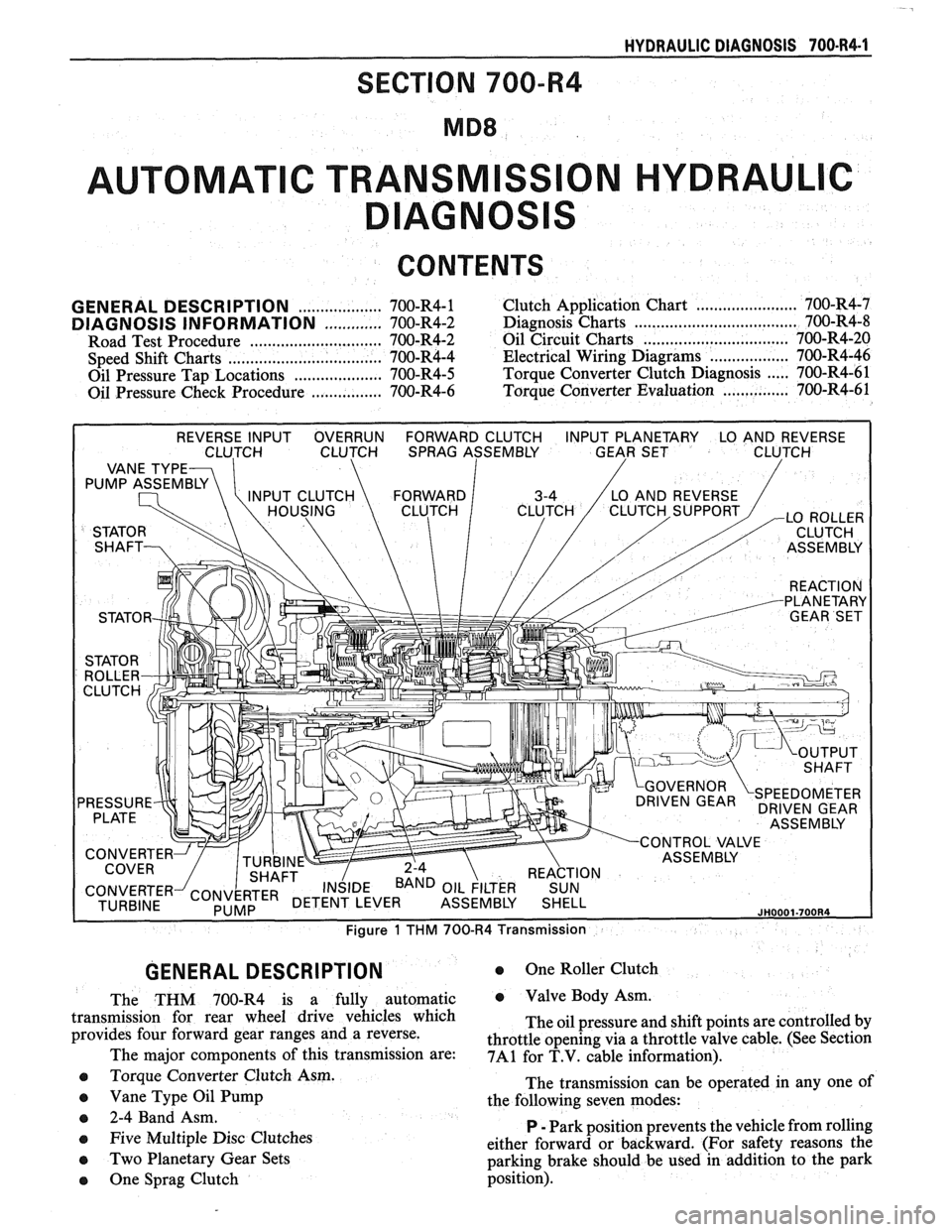
GENERAL DESCRIPTION
The THM 700-R4 is a fully automatic
transmission for rear wheel drive vehicles which
provides four forward gear ranges and a reverse.
The major components of this transmission are:
e Torque Converter Clutch Asm.
e Vane Type Oil Pump
e 2-4 Band Asm.
e Five Multiple Disc Clutches
0 Two Planetary Gear Sets
0 One Sprag Clutch
0 One Roller Clutch
e Valve Body Asm.
The oil pressure and shift points are controlled by
throttle opening via a throttle valve cable. (See Section
7A1 for T.V. cable information).
The transmission can be operated in any one of
the following seven modes:
P
- Park position prevents the vehicle from rolling
either forward or backward. (For safety reasons the
parking brake should be used in addition to the park
position).
Page 991 of 1825

700-R4-2 HYDRAULIC DIAGNOSIS
R - Reverse allows the vehicle to be operated in
a rearward direction.
N - Neutral allows the engine to be started and
operated without driving the vehicle. If necessary this
position may be selected if the engine must be restarted
with the vehicle moving.
D - Overdrive is used for all normal driving
conditions. It provides four gear ratios plus converter
clutch operation. Downshifts are available for safe
passing by depressing the accelerator.
D - Drive position is used for city traffic, hilly
terrain, and trailer towing. It provides three gear
ranges. Again, downshifts are available by depressing
the accelerator.
2 - Manual second is used to provide acceleration
and engine braking. This range may be selected at any
vehicle speed.
1 - Manual Lo is used to provide maximum
engine
brlking. This range may also be selected at any
vehicle speed.
DIAGNOSIS INFORMATION
ROAD TEST PROCEDURE
e Perform the road test following the sequence
given
e MPH (KPH) shift points will vary with actual
throttle position and driver habits
e Compare the results of the test with speed shift
chart information. Use these results with the
diagnosis information contained in this
Automatic Transmission Hydraulic Diagnosis
Section to evaluate the transmission.
e This test should only be performed when traffic
and road conditions permit
e Observe all traffic safety regulations
Drive and Reverse Engagement Shift Check
1. Start engine
2. Depress brake pedal
3. Move gear selector:
- "Park" (P) to "Reverse" (R)
- "Reverse" (R) to "Neutral"
(N) to "Drive" (D)
Gear selections should be immediate and
not harsh.
Upshifts and Torque Converter Clutch (TCC)
Apply (Figure
2)
With gear selector in "Overdrive" (D)
1. Accelerate using a steady increasing throttle
pressure
2. Note the shift speed point gear engagements for:
- 2nd gear
- 3rd gear
- Overdrive
3. Note the speed shift point for TCC apply. This
should occur while in third gear or overdrive. If
the apply is not noticed, refer to the Preliminary
Torque Converter Clutch Diagnosis information
contained in this section of the Service Manual.
Important
The torque converter clutch will not engage if
engine coolant has not reached a minimum
operating temperature of approximately 54°C
(1 30°F).
Part Throttle Downshift
At vehicle speeds of 40-55 MPH (64-88
KPH) quickly depressed the accelerator to
a half open position and observe:
- TCC releases
- Transmission downshift to 3rd gear
immediately
Full Throttle (Detent) Downshift
At vehicle speeds of 48-55 MPH (77-88
KPH) quickly depress the accelerator to a
wide open position and observe:
- TCC releases
- Transmission downshifts to 2nd gear
immediately
Manual Downshift
1. At vehicle speeds of 40-55 MPH (64 to 88 KPH)
release the accelerator pedal while moving the
gear selector to "Third" gear (D) and observe:
- TCC release
- Transmission downshift to 3rd gear should
be immediate
- Engine should slow vehicle down
2. Move gear selector to "Overdrive" and accelerate
to 40-45 MPH (64-72 KPH). Release the
accelerator pedal while moving the gear selector
to "Second" gear (2) and observe.
- TCC release
- Downshift to second gear should be
immediate
- Engine should slow vehicle down
3. Move gear selector to "Overdrive" (D) and
accelerate to 25 MPH (40 KPH). Release the
accelerator pedal while moving the gear selector
to "First" gear (1) and observe:
- TCC release
- Transmission downshift to 1st gear should
be immediate
- Engine should slow vehicle down
Coastdown Downshift
1. With the gear selector in "Overdrive" (D)
accelerate to 4th gear with TCC applied.
2. Release the accelerator pedal and lightly apply
the brakes to observe:
- TCC release
- Shift points for downshifts.
Manual Gear Range Selection
MANUAL THIRD (D)
1. With vehicle stopped, place gear selector in
"Third" (D) and accelerate to observe:
Page 995 of 1825
700-R4-6 HYDRAULIC DIAGNOSIS
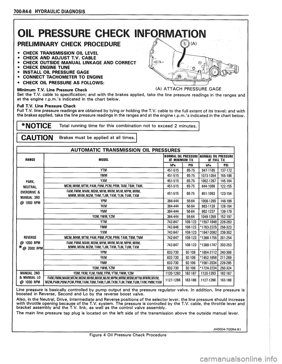
L PRESSURE CHECK NFORMAT
PRELIMINARY CHECK PROCEDURE
0 CHECK TRANSMISSION OIL LEVEL 0 CHECK AND ADJUST T.V. CABLE
0 CHECK OUTSIDE MANUAL LINKAGE AND CORRECT
@ CHECK ENGINE TUNE
0 INSTALL OIL PRESSURE GAGE
CONNECT TACHOMETER TO ENGINE
0 CHECK OIL PRESSURE AS FOLLOWS:
Minimum T.V. Line Pressure Check (A) ATTACH PRESSURE GAGE
Set the T.V. cable to specification; and with the brakes applied, take the line pressure readings in the ranges and
at the engine
r.p.m.'s indicated in the chart below.
Full T.V. Line Pressure Check Full T.V. line pressure readings are obtained by tying or holding the T.V. cable to the full extent of its travel; and with
the brakes applied, take the line pressure readings in the ranges and at the engine
r.p.m.'s indicated in the chart below.
MODEL
Line pressure is basically controlled by pump output and the pressure regulator valve. In addition, line pressure is
boosted in Reverse, Second and Lo by the reverse boost valve.
Also, in the Neutral, Drive, Intermediate and Reverse positions of the selector lever, the line pressure should increase
with throttle opening because of the T.V. system. The pressure is controlled by the T.V. cable, the throttle lever and
bracket assembly and the T.V. link, as well as the control valve assembly.
The main line pressure tap plug is located on the left side of the transmission above the outside manual lever.
Figure
4 Oil Pressure Check Procedure
Page 1050 of 1825
TORQUE CONVERTER CLUTCH (TCC)
DIAGNOSIS
To properly diagnose the Torque Converter
Clutch (TCC) system, perform all electrical
testing first and then the hydraulic testing. Refer
to the Torque Converter Section
6E2-C8 for
additional information.
The TCC is applied by fluid pressure which is
controlled by a solenoid located inside the Automatic
Transmission assembly. The solenoid is energized or
released by making or breaking an electrical circuit
through a combination of switches and sensors.
TCC Electrical Diagnosis
e For electrical diagnosis of TCC, refer to the
specific vehicle section in Section
8A, Electrical
Diagnosis.
e For diagnosis of emission control related
components of TCC, Refer to the specific section
of
6E, Driveability and Emissions.
e For the diagnosis of TCC Hydraulic Controls,
refer to the Procedure and Wiring Diagrams
provided in this section.
Functional Check Procedure
rn Inspect
1. Install a tachometer
2. Operate the vehicle until proper operating
temperature is reached
3. Drive vehicle at 50-55 mph (80-88 Km/h) with
light throttle (road load)
4. Maintaining throttle lightly touch the brake
pedal and check for a slight bump when the TCC
releases and a slight increase in engine RPM.
5. Release the brake, slowly accelerate and check for
a re-apply of the converter clutch and a slight
decrease in engine RPM.
Preliminary Checking Procedure
The purpose of the preliminary checking
procedure is to isolate external (electrical) problems
from internal (electrical or mechanical) ones.
Important
e Use only a scale type ohmmeter. High impedance
type ohmmeters and those with a digital readout
will not work.
e An ALCL scanner may be used to verify the
electrical circuit. Remember, a completed circuit
does not indicate that the solenoid will apply.
e Do not bench test using an automotive type
battery. Accidentally crossed wires will damage
the internal diodes of the TCC solenoid.
HYDRAULIC DIAGNOSIS 700-R4-61
External Controls
rn Inspect
e Connect voltmeter between transmission
connector and ground.
e Turn key "ON"
e If 0 or low voltage is found, refer to Sections 6E
and 8A for electrical diagnosis.
e If 12 volts are present at the connector, refer to
the TCC hydraulic diagnosis.
TORQUE CONVERTER EVALUATION
Torque Converter Stator
The Torque Converter Stator roller clutch can
have one of two different type malfunctions:
A. Stator Assembly freewheels in both
directions.
B. Stator Assembly remains locked up at all
times.
Condition A-Poor Acceleration Low Speed
The vehicle tends to have poor acceleration from
a standstill. At speeds above 30-35 mph (50-55
km/h),
the car may act normal. If poor acceleration is noted,
it should first be determined that the exhaust system
is not blocked, the engine timing is correct and the
transmission is in first
(1st) gear when starting out.
If the engine freely accelerates to high
r.p.m. in
"NEUTRAL" (N), it can be assumed that the engine
and exhaust system are normal. Checking for poor
performance in "Drive" and Reverse will help
determine if the stator is freewheeling at all times.
Condition B-Poor Acceleration High Speed
Engine r.p.m. and car speed limited or restricted
at high speeds. Performance when accelerating from a
standstill is normal. Engine may over-heat. Visual
examination of the converter may reveal a blue color
from over-heating.
If the converter has been removed, the stator
roller clutch can be checked by inserting a finger into
the splined inner race of the roller clutch and trying to
turn the race in both directions. The inner race should
turn freely clockwise, but not turn or be very difficult
to turn counterclockwise.
The Converter Should Be Replaced If:
e Leaks externally, such as at the hub weld area.
e Converter has an imbalance which cannot be
corrected. (Refer to Converter Vibration Test
Procedure).
e Converter is contaminated with engine coolant
containing antifreeze.
The Converter Should Not Be Replaced If:
e The oil has an odor, is discolored, and there is no
evidence of metal or clutch facing particles.
e The threads in one or more of the three converter
bolt holes are damaged.
- Correct with thread insert. (Refer to Section
6A).
Page 1066 of 1825
AUTOMATIC TRANSMISSION 700.84-1 5
(A) APPLY AIR PRESSURE WERE TO REMOVE
LO & REVERSE PISTON FROM THE CASE
Third Accumulator Retainer and Ball Assembly
(80) (Figure 99)
Ball
- missing
- sticking or leaking
Retainer
- missing
- loose
- not seated correctly
- feed slots restricted
Retainer and Ball Assembly Leak Check
Procedure
Important (Figure 99)
1. Install the servo assembly into the servo
bore.
2. Install the servo cover and retainer.
3. Pour a suitable solvent into the accumulator
bore.
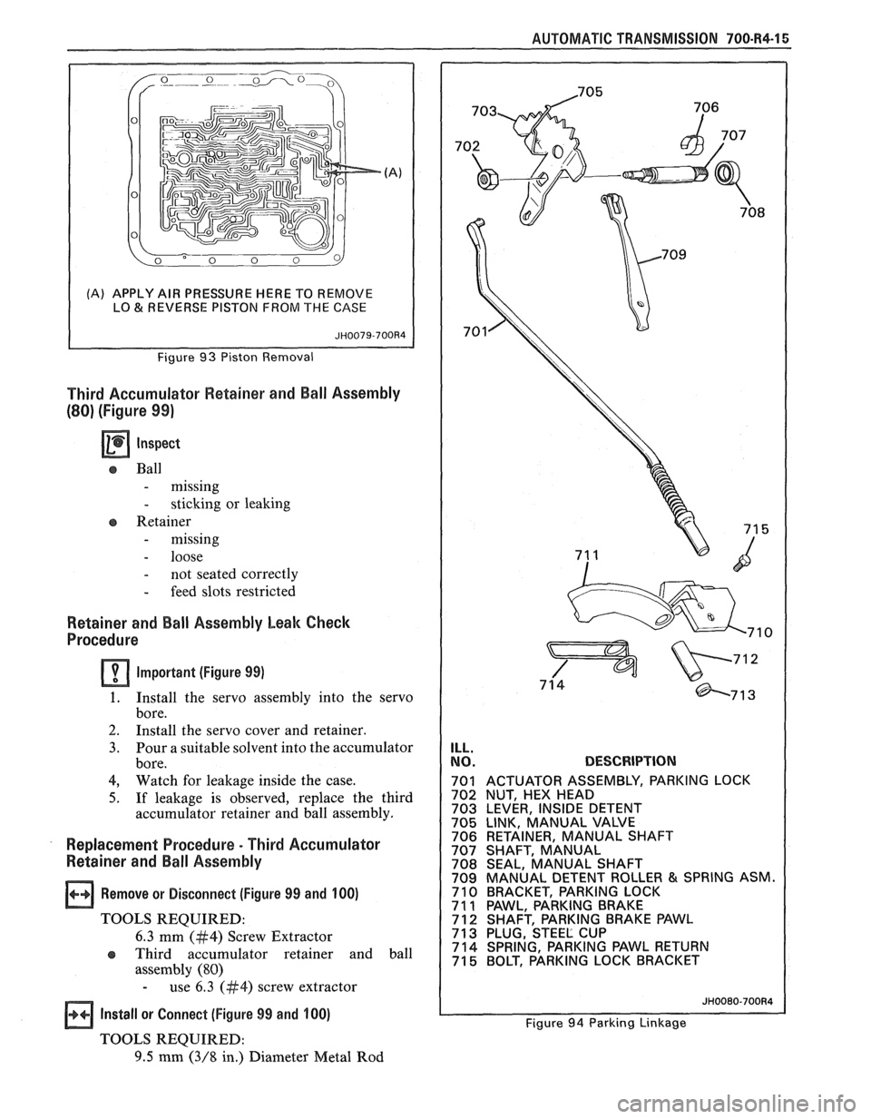
DESCRIPTION
701 ACTUATOR ASSEMBLY, PARKING LOCK
Replacement Procedure - Third Accumulator 706 RETAINER, MANUAL SHAFT
707 SHAFT, MANUAL Retainer and Ball Assembly 708 SEAL, MANUAL SHAFT 709 MANUAL DETENT ROLLER & SPRING ASM.
1 Remove or Disconnect (Figure 99 and 100) 710 BRACKET, PARKING LOCK 7 1 1 PAWL, PARKING BRAKE TOOLS REQUIRED: 7 12 SHAFT, PARKING BRAKE PAWL
6.3 mm (#4) Screw Extractor 71 3 PLUG, STEEL CUP
assembly (80)
- use 6.3 (#4) screw extractor
1 Install or Connect (Figure 99 and 100) Figure 94 Parking Linkage
TOOLS REQUIRED:
9.5 mm (3/8 in.) Diameter Metal Rod
Page 1069 of 1825
700-R4.18 AUTOMATIC TRANSMISSION
Case Assembly
a Clean
o Thoroughly with solvent
a Air dry
- do not wipe with cloth
Lo and Reverse Clutch Assembly
lnspect (Figure 101)
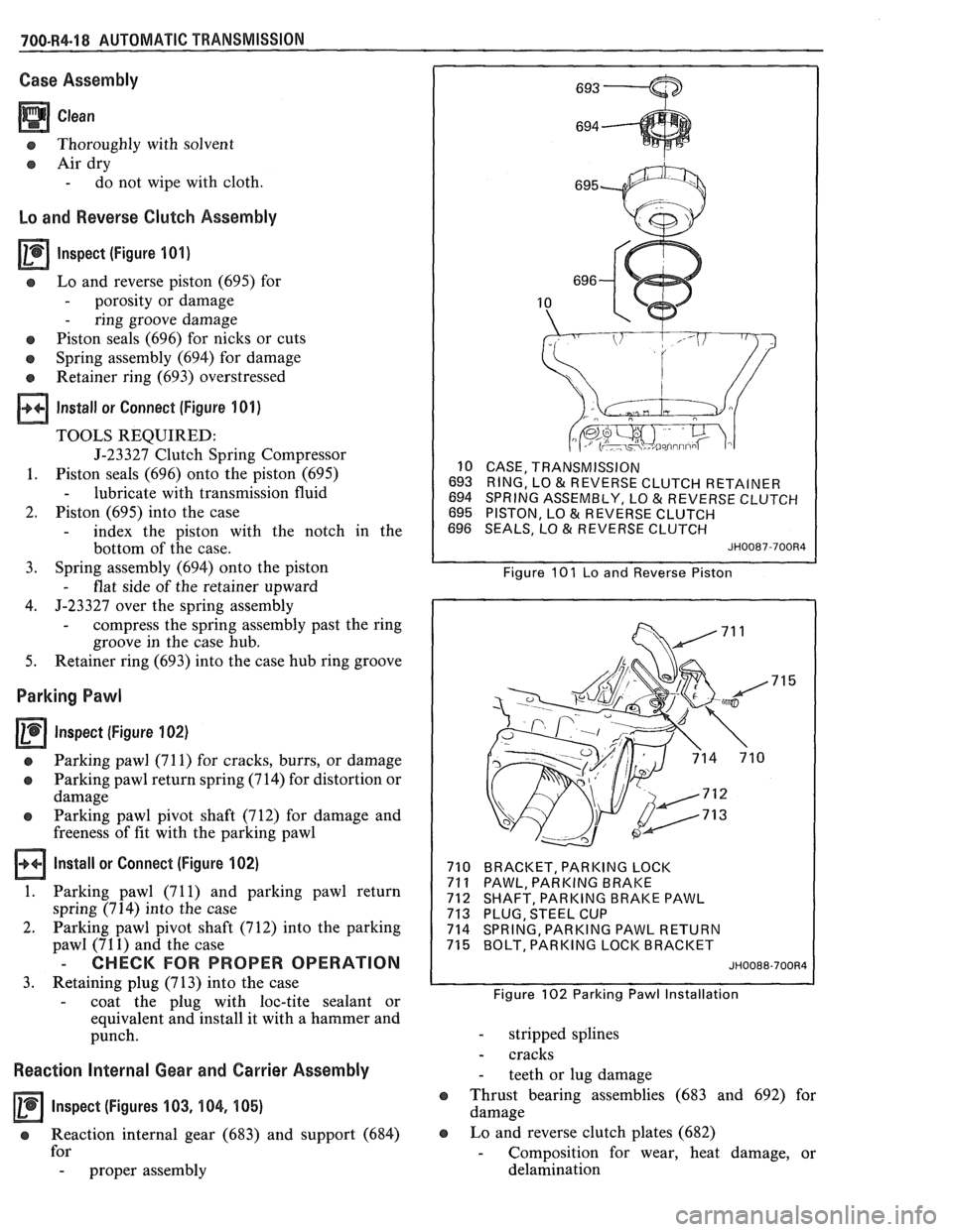
s Lo and reverse piston (695) for
- porosity or damage
- ring groove damage
e Piston seals (696) for nicks or cuts
o Spring assembly (694) for damage
Retainer ring (693) overstressed
Install or Connect (Figure 101)
TOOLS REQUIRED:
J-23327 Clutch Spring Compressor
1. Piston seals (696) onto the piston (695)
- lubricate with transmission fluid
2. Piston (695) into the case
- index the piston with the notch in the
bottom of the case.
3. Spring
assembly (694) onto the piston
- flat side of the retainer upward
4. J-23327 over
the spring assembly
- compress the spring assembly past the ring
groove in the case hub.
5. Retainer ring (693) into the case hub ring groove
Parking Pawl
Inspect (Figure 102)
a Parking pawl (71 1) for cracks, burrs, or damage
o Parking pawl return spring (714) for distortion or
damage
e Parking pawl pivot shaft (712) for damage and
freeness of fit with the parking pawl
Install or Connect (Figure 102)
1. Parking pawl (71 1) and parking pawl return
spring (714) into the case
2. Parking pawl pivot shaft (712) into the parking
pawl (71
1) and the case
- CHECK FOR PROPER OPERATION
3. Retaining plug (713) into the case
- coat the plug with loc-tite sealant or
equivalent and install it with a hammer and
punch.
Reaction Internal Gear and Carrier Assembly
Inspect (Figures 103, 104, 105)
e Reaction internal gear (683) and support (684)
for
- proper assembly
10 CASE, TRANSMISSION
693 RING, LO
& REVERSE CLUTCH RETAINER
694 SPRING ASSEMBLY, LO & REVERSE CLUTCH
695 PISTON, LO & REVERSE CLUTCH
696 SEALS, LO & REVERSE CLUTCH
JH0087-700R4
Figure 101 Lo and Reverse Piston
710 BRACKET, PARKING LOCK
71
1 PAWL, PARKING BRAKE
712 SHAFT, PARKING BRAKE PAWL
713 PLUG, STEEL CUP
714 SPRING, PARKING PAWL RETURN
715 BOLT, PARKING LOCK BRACKET
JH0088-700R4
Figure 102 Parking Pawl Installation
- stripped splines
- cracks
- teeth or lug damage
e Thrust bearing assemblies (683 and 692) for
damage
e Lo and reverse clutch plates (682)
- Composition for wear, heat damage, or
delamination