1988 PONTIAC FIERO brake
[x] Cancel search: brakePage 1278 of 1825
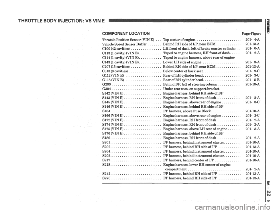
THROTTLE BODY INJECTION: V8 VIN E
COMPONENT LOCATION Page-Figure
........................ Throttle Position Sensor (VIN E) ... Top center of engine 201- 4-A
............. Vehicle Speed Sensor Buffer ....... Behind RN side of IIP. near ECM 201-13-A
.. el00 (42 cavities) ................ LH front of dash. left of brake master cylinder 201- 0-A
...... C113 (1 cavity) (VIN E) ............ Taped to engine harness. RH front of dash 201- 2-A
............ C114 (1 cavity) (VIN E) Taped
to engine harness. above rear of engine
C143 (1 cavity) (VIN E) ............ Lower LH side of engine .................... 201- 3-A
C207 (15
cavities) ................ Behind RN side of IIP. near ECM ............. 201-13-A
C313
(3 cavities) ................. Below center of back seat .................... 201- 9-6
6112 (VIN E) ................... Rear of LH cylinder head .................... 201- 3-C
. 6118 (VIN E) ................... Rear of RH cylinder head .................... 201- 5-B
6200
.......................... Behind IIP. left of steering colulm ............ 201-10-A
6304
.......................... Under rear seat. on support bracket
S142 (VIN E) .................... Engine harness. behind RN side of IIP
S143 (VINE) .................... Engine harness. RH front of dash ............. 201- 2-A
S145
(VIN E) .................... Engine harness. above rear of engine .......... 201- 3-C
S146 (VIN E) .................... Engine harness. behind RH side of IIP
S164 ........................... IIP harness. above Fuse Block ................ 201-10-A
S166 (VINE) .................... Engine harness. above rear of engine .......... 201- 3-C
S172 (VIN E) .................... Engine harness. RN front of dash ............. 201- 2-8
S174 (VIN E) .................... Engine harness. RH front of dash ............. 201- 2-8
S175 (VIM E) .................... Engine harness. above LH rear of engine ....... 201- 3-A
S176
(VIN E) .................... Engine harness. behind RH side of IIP
S186 ........................... Engine harness. R W. front of dash ............. 281- 2-A
S201
........................... IIP harness. behind instmmend cluster ......... 201-10-A
S202 ........................... IIP harness. behind RH side of IIP ............ 201-13-A
S204 ........................... IIP harness. be&d instnnment cluster ......... 201-10-A
S205
........................... IIP harness. behind instrument cluster ......... 201-10-A
S217 ........................... IIP harness. bebd center of IIP .............. 201-18-A
S218
........................... Engine harness. lower RH comer of engine
compartment
............................ 201- 2-8
S242 ........................... IIP harness. bebd RH side of IIP ............ 201-13-A
S276 ........................... IIP harness. behind RW side of Ill? ............ 201-13-A
Page 1289 of 1825
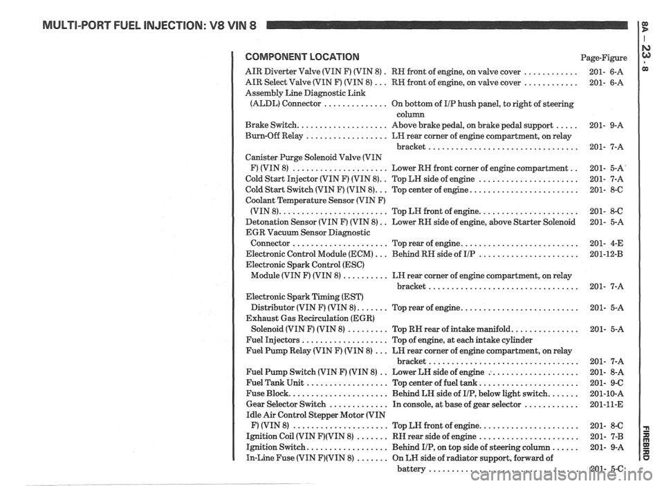
MULTI-PORT FUEL INJECTION: V8 VIN 8 It
COMPONENT LOCATION Page-Figure
. ............ AIR Diverter Valve (VIN F) (VIN 8)
RN front of engine. on valve cover 201- 6-A
............ AIR Select Valve (VIN F) (VIN 8) ... RW front of engine. on valve cover 201- 6-A
Assembly Line Diagnostic Link
(ALDL) Connector
.............. On bottom of I/P hush panel. to right of steering
column
..... Brake Switch .................... Above brake pedal. on brake pedal support 201- 9-A
Burn-Off Relay
.................. LH rear corner of engine compartment. on relay
bracket
................................. 201- 7-A
Canister Purge Solenoid Valve (VIN
.. F) (VIN 8) ..................... Lower RH front corner of engine compartment 201- 5-A'
.. ...................... Cold Start Injector (VIN F) (VIN 8) Top LH side of engine 201- 7-A
........................ Cold Start Switch (VIN F) (VIN 8) ... Top center of engine 201- 8-6
Coolant Temperature Sensor (VIN F)
...................... (VIN 8) ........................ Top LN front of engine 201- 8-C
Detonation Sensor (VIN F) (VIN 8)
. . Lower RN side of engine. above Starter Solenoid 201- 5-A
EGR Vacuum Sensor Diagnostic
.......................... Connector ..................... Top rear of engine 201- 4-E
...................... Electronic Control Module (ECM) ... Behind RH side of IIP 201-12-B
Electronic Spark Control (ESC)
Module (VIN F) (VIN 8)
.......... LH rear corner of engine compartment. on relay
bracket
................................. 201- 7-A
Electronic Spark Timing (EST)
.......................... Distributor (VIN F) (VIN 8) ....... Top rear of engine 201- 5-A
Exhaust Gas Recirculation (EGR)
............... Solenoid (VIN F) (VIN 8) ......... Top RN rear of intake manifold 201- 5-A
Fuel Injectors
................... Top of engine. at each intake cylinder
Fuel Pump Relay (VIN F) (VIN 8)
... LH rear corner of engine compartment. on relay
bracket
................................. 201- 7-A
.. ................... Fuel Pump Switch (VIN F) (VIN 8)
Lower LH side of engine : 201- 8-A
...................... Fuel Tank Unit .................. Top center of fuel tank 201- 9-C
....... Fuse Block ...................... Behind LH side of IIP. below light switch 201-10-A
............ Gear Selector Switch ............. In console. at base of gear selector 201-11-E
Idle Air Control Stepper Motor (VIN
...................... F) (VIN 8) ..................... Top LN front of engine 201- 8-C
...................... Ignition Coil (VIN F)(VIN 8) ....... RH rear side of engine 201- 7-B
...... Ignition Switch .................. Behind IIP. on top side of steering column 201- 9-A
In-Line Fuse (VIN F)(VIN 8) ....... On LH side of radiator support. forward of
battery
................................. 201- 5-C
Page 1290 of 1825
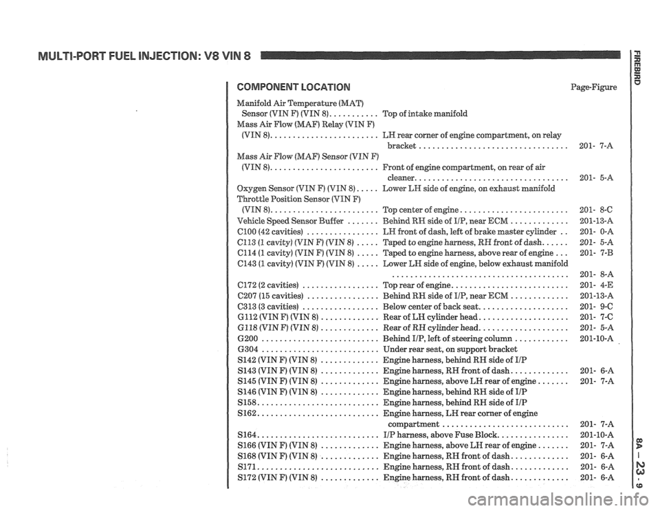
MULTI-PQRT FUEL INJECTION: V8 VIN 8
COMPONENT LOCATION Page-Figure
Manifold
Air amperatwe (MAT)
........... Sensor (VIN F) (VIN 8) Top of intake manifold
Mass
Air Flow (MAF) Relay (VIN F)
........................ (VIN 8) LH rear corner of engine compartment. on relay
bracket
.................................
Mass Air Flow (MAF) Sensor (VIN F)
........................ (VIN 8) Front of engine coqartment. on rear of air
.................................. cleaner
Oxygen Sensor (VIN F) (VIN 8) ..... Lower LW side of engine. on exhaust manifold
Throttle Position Sensor (VIN
F)
........................ (VIN 8)
Top center of engine ........................
....... ............. Vehicle Speed Sensor Buffer BeGnd RH side of IIP. near ECM
................ C100 (42 cavities) LH front of dash. left of brake master cylinder ..
6113 (1 cavity) (VIN F) (VIM 8) ..... Taped to engine harness. RH front of dash ......
C114 (1 cavity) (VIN F) (VIN 8) ..... Taped to engine harness. above rear of engine ...
C143 (1 cavity) (VIN F) (VIN 8) ..... Lower LH side of engine. below exhaust manifold
.......................................
.......................... ................. C172 (2 cavities)
Top rear of engine
................ C207 (15 cavities)
Behind RI-I side of IIP. near ECM .............
................. .................... C313 (3 cavities) Below center of back seat
............. GI12 (VIN F) (VIN 8)
Rear of LN cylinder head ....................
............. .................... 6118 (VIN F) (VIN 8) Rear of RH cylinder head
.......................... 6200
Behind IIP. left of steering column ............
.......................... 6304
Under rear seat. on support bracket
............. S142 (VIN F) (VIN 8)
Engine harness. behind RH side of IIP
............. ............. S143 (VIN F) (VIN 8) Engine harness. RH front of dash
............. S145 (VIN F) (VIN 8)
Engine harness. above LH rear of engine .......
............. S146 (VIN F) (VIN 8)
Engine harness. behind RH side of IIP
........................... S158
Engine harness. behind RN side of IIP
........................... S162 Engine harness. LK rear corner of engine
compartment
............................
........................... S164 I/P harness. above Fuse Block ................
............. S166 (VIN F) (VIN 8) Engine harness.
above LN rear of engine .......
............. ............. S168 (VIN F) (VIN 8) Engine harness. RH front
of dash
........................... ............. S171 Engine harness. RN front of dash
1 S172 (VIN F) (VIN 8) ............. ~n& harness. RH front of dash .............
Page 1296 of 1825
TROUBLESHOOTING HINTS
STARTER
Try the following checks before doing
the Sys-
tem Diagnosis
.
1 . Check the hydrometer eye that is built into
the vehicle Battery before troubleshooting
the Starter System
.
. Green eye . Battery is charged .
. Dark eye . Battery is discharged . Recharge
Battery
.
- Clear or yellow eye . Battery fluid is low .
Replace Battery .
2 . Check that the Starter Solenoid te
and B and battery
connections are clean and
tight
.
3 . Check that grounds 6100 and 6103 are
clean and tight
.
Go to System Diagnosis for diagnostic tests .
SYSTEM DIAGNOSIS
STARTER
NOTE:
The following tests are designed for
engines and batteries at normal operat-
ing temperatures and assumes that
there are no engine symptoms which
could cause a no start condition
. To use
the tests under other conditions could
result in misdiagnosis
.
Diagnostic steps for the symptorns listed in
the following table are listed after the table
.
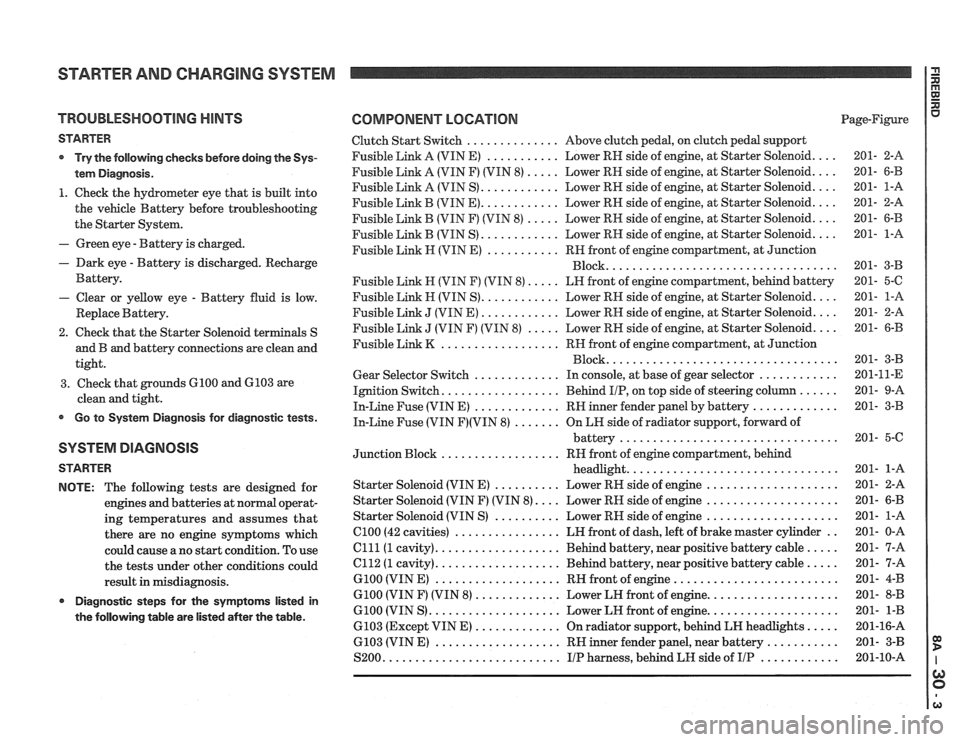
COMPONENT LOCATION Page-Figure
Clutch Start Switch
.............. Above clutch pedal. on clutch pedal support
Fusible Link A (VIN E)
........... Lower RH side of engine. at Starter Solenoid .... 201- 2-A
Fusible Link A (VIN F) (VIN
8) ..... Lower RH side of engine. at Starter Solenoid .... 201- 6-B
Fusible Link A (VIN S)
............ Lower RH side of engine. at Starter Solenoid .... 201- 1-A
Fusible Link B (VIN
E) ............ Lower RH side of engine. at Starter Solenoid .... 201- 2-A
Fusible Link
B (VIN F) (VIN 8) ..... Lower RH side of engine. at Starter Solenoid .... 201- 6-B
Fusible Link B (VIN S)
............ Lower RH side of engine. at Starter Solenoid .... 201- 1-A
Fusible Link
H (VIN E) ........... RN front of engine compartment. at Junction
................................... Block 201- 3-B
Fusible Link
H (VIN F) (VIN 8) ..... LH front of engine compartment. behind battery 201- 5-C
Fusible
Link H (VIN S) ............ Lower RH side of engine. at Starter Solenoid .... 201- 1-A
Fusible Link
J (VIN E) ............ Lower RH side of engine. at Starter Solenoid .... 201- 2-A
Fusible Link
J (VIN F) (VIN 8) ..... Lower RH side of engine. at Starter Solenoid .... 201- 6-B
Fusible Link
K .................. RH front of engine compartment. at Junction
................................... Block 201- 3-B
Gear Selector Switch
............. In console. at base of gear selector ............ 201-11-E
Ignition Switch
.................. Behind IIP. on top side of steering column ...... 201- 9-A
In-Line Fuse (VIN E)
............. RH inner fender panel by battery ............. 201- 3-B
In-Line Fuse (VIN F)(VIN 8) ....... On LN side of radiator support. forward of
battery
................................. 201- 5-C
Junction Block
.................. RH front of engine compartment. behind
headlight
................................ 201- 1-A
Starter Solenoid (VIN
E) .......... Lower RH side of engine .................... 201- 2-A
Starter Solenoid (VIN F) (VIN
8) .... Lower RH side of engine .................... 201- 6-B
Starter Solenoid (VIN S)
.......... Lower RH side of engine .................... 201- 1-A
el00 (42 cavities) ................ LH front of dash. left of brake master cylinder .. 201- 0-A
Clll(1 cavity) ................... Behind battery. near positive battery cable ..... 201- 7-A
el12 (1 cavity) ................... Behind battery. near positive battery cable ..... 201- 7-A
G100 (VIN E) ................... RH front of engine ......................... 201- 4-B
G100 (VIN F) (VIN 8) ............. Lower LH front of engine .................... 201- 8-B
6100 (VIN S) .................... Lower LH front of engine .................... 201- 1-B
6103 (Except VIN
E) ............. On radiator support. behind LH headlights ..... 201-16-A
6103 (VIN
E) ................... RH inner fender panel. near battery ........... 201- 3-B
S200
........................... IIP harness. behind LH side of IIP ............ 201-10-A
Page 1303 of 1825
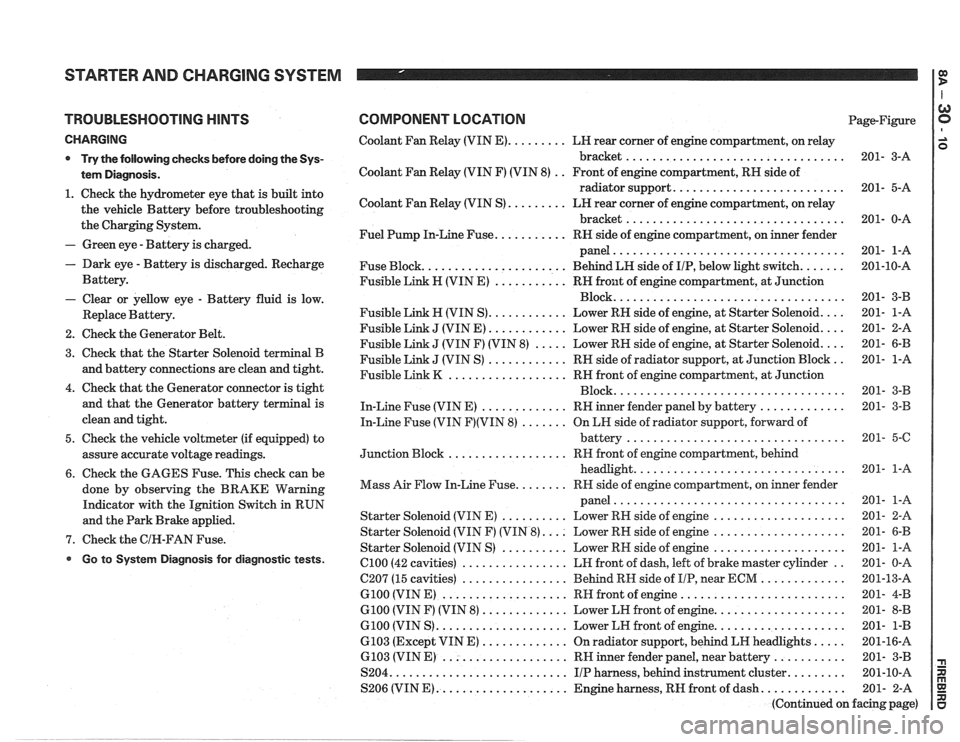
STARTER AND CHARGING SYSTEM
TROUBLESHOOTING HINTS
CHARGING
* Try the following checks before doing the Sys-
tem Diagnosis
.
1 . Check the hydrometer eye that is built into
the vehicle Battery before troubleshooting
the Charging System
.
- Green eye . Battery is charged .
. Dark eye . Battery is discharged . Recharge
Battery
.
- Clear or yellow eye . Battery fluid is low .
Replace Battery .
2 . Check the Generator Belt .
3 . Check that the Starter Solenoid terminal B
and battery connections are clean and tight
.
4 . Check that the Generator connector is tight
and that the Generator battery terminal is
clean and tight
.
5 . Check the vehicle voltmeter (if equipped) to
assure accurate voltage readings
.
6 . Check the GAGES Fuse . This check can be
done by observing the BRAKE Warning
Indicator with the Ignition Switch in RUN
and the Park Brake applied
.
7 . Check the GIN-FAN Fuse .
Go to System Diagnosis for diagnostic tests .
COMPONENT LOCATION Page-Figure
Coolant Fan Relay (VIN
E) ......... LH rear corner of engine compartment. on relay
bracket
................................. 201- 3-A
Coolant Fan Relay (VIN F) (VIN 8)
. . Front of engine compartment. RH side of
radiator support
.......................... 201- 5-A
Coolant Fan Relay (VIN S)
......... LN rear corner of engine compartment. on relay
bracket
................................. 201- 0-A
Fuel Pump In-Line Fuse
........... RH side of engine compartment. on inner fender
panel
................................... 201- 1-A
Fuse Block
...................... Behind LN side of IIP. below light switch ....... 201-10-A
Fusible Link H (VIN E)
........... RH front of engine compartment. at Junction
................................... Block 201- 3-B
Fusible Link
H (VIN S) ............ Lower RN side of engine. at Starter Solenoid .... 201- 1-A
Fusible Link
J (VIN E) ............ Lower RH side of engine. at Starter Solenoid .... 201- 2-A
Fusible Link
J (VIN F) (VIN 8) ..... Lower RH side of engine. at Starter Solenoid .... 201- 6-B
Fusible Link
J (VIN S) ............ RH side of radiator support. at Junction Block .. 201- 1-A
Fusible Link
K .................. RH front of engine compartment. at Junction
................................... Block 201- 3-B
In-Line Fuse (VIN E)
............. RH inner fender panel by battery ............. 201- 3-B
In-Line Fuse (VIN
F)(VIN 8) ....... On LH side of radiator support. forward of
................................. battery 201- 5-6
.................. Junction Block RH
front of engine compartment. behind
................................ headlight 201- 1-A
........ Mass Air Flow In-Line Fuse RR side of engine compartment. on inner fender
................................... panel 201- 1-A
Starter Solenoid (VIN E)
.......... Lower RH side of engine .................... 201- 2-A
Starter Solenoid (VIN F) (VIN
8) .... Lower RH side of engine .................... 201- 6-B
Starter Solenoid (VIN S)
.......... Lower RN side of engine .................... 201- 1-A
el00 (42 cavities) ................ LH front of dash. left of brake master cylinder .. 201- 0-A
C207 (15 cavities)
................ Behind RH side of IIP. near ECM ............. 201-13-A
G100 (VIN E) ................... RH front of engine ......................... 201- 4-B
G100 (VIN F) (VIN 8) ............. Lower LH front of engine .................... 201- 8-B
G100 (VIN S) .................... Lower LH front of engine .................... 201- 1-B
6103 (Except VIN E) ............. On radiator support. behind LH headlights ..... 201-16-A
6.103 (VIN E) ................... RH inner fender panel. near battery ........... 201- 3-B
S204
........................... IIP harness. behind instrument cluster ......... 201-10-A
S206 (VIN
E) .................... Engine harness. RH front of dash ............. 201- 2-A
(Continued on facing page)
Page 1318 of 1825
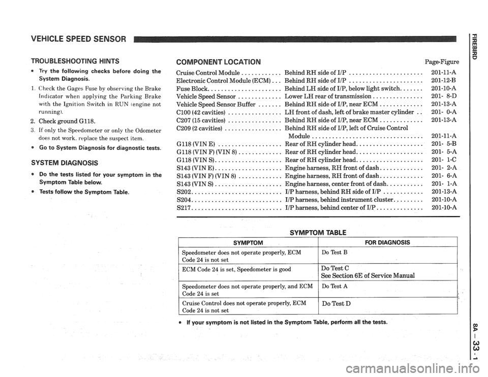
VEHICLE SPEED SENSOR
TROUBLESHOOTING HINTS
0 Try the following checks before doing the
System Diagnosis
.
1
. Check the Gages Fuse by observing the Brake
Indicator when applying the Parking Brake
wrth the Ignition Switch in RUN (engine not
running)
.
2 . Check ground 6118 .
3 . If only the Speedometer or only the Odometer
does not work. replace the suspect item
.
Go to System Diagnosis for diagnostic tests .
SYSTEM DlAGNOSlS
Do the tests listed for your symptom in the
Symptom Table below
.
Tests follow the Syrnptom Table .
COMPONENT LOCATION Page-Figure
Cruise Control Module
............ Behind RN side of IlP ...................... 201-11-A
Electronic Control Module (ECM)
... Behind RN side of IIP ...................... 201-12-B
Fuse Block
...................... Behind LN side of IIP. below light switch ....... 201-10-A
Vehicle Speed Sensor
............. Lower LEI rear of transmission ............... 201- 8-D
Vehicle Speed Sensor Buffer
....... Behind RH side of IIP. near ECM ............. 201-13-A
ClOO (42 cavities) ................ LN front of dash. left of brake master cylinder .. 201- 0-A
C207 (15 cavities) ................ Behind RH side of IIP. near ECM ............. 201-13-A
C209 (2 cavities)
................. Behind RN side of IIP. left of Cruise Control
................................. Module 201-11-A
6118 (VIN E)
................... Rear of RH cylinder head .................... 201- 5-B
6118 (VIN F) (VIN 8) ............. Rear of RN cylinder head .................... 201- 5-A
6118 (VIN S)
.................... Rear of RN cylinder head .................... 201- 1-C
S143 (VINE)
.................... Engine harness. RH front of dash ............. 201- 2-A
S143 (VIN F) (VIN
8) ............. Engine harness. RN front of dash ............. 201- 6-A
S143 (VIN S)
.................... Engine harness. center front of dash ........... 201- 1-A
S202
........................... IIP harness. behind RH side of IIP ............ 201-13-A
S204
........................... IIP harness. behind instrument cluster ......... 201-10-A
S217 ........................... IIP harness. behind center of IIP .............. 201-10-A
SYMPTOM TABLE
I SYMPTOM I FOR DIAGNOSIS I
=liter does not operate properly. ECM I Do Test B
code 24 is not set
ECM Code
24 is set. Speedometer is good
e If your symptom is not listed in the Symptom Table. pedorm all the tests .
Do Test C
See Section 6E of Service Manual
Speedometer does not operate properly. and ECM
Code
24 is set
Cruise Control does not operate properly. ECM
Code
24 is not set Do
Test
A
Do Test D
Page 1323 of 1825
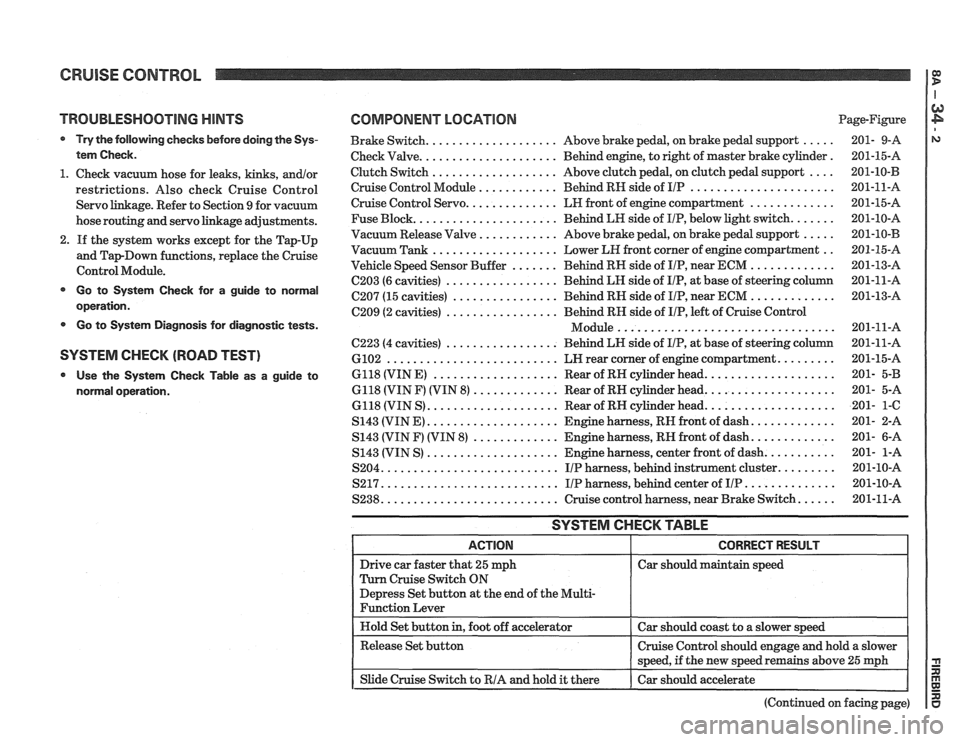
CRUISE CONTROL
TROUBLESHOOTING HINTS
Try the following checks before doing the Sys-
tem Check
.
1 . Check vacuum hose for leaks. kinks. andlor
restrictions . Also check Cruise Control
Servo linkage
. Refer to Section 9 for vacuum
hose routing and servo linkage adjustments
.
2 . If the system works except for the Tap-Up
and
TapDown functions. replace the Cruise
Control Module
.
Go to System Check for a guide to normal
operation
.
Go to System Diagnosis for diagnostic tests .
SYSTEM CHECK (ROAD TEST)
Use the System Check Table as a guide to
normal operation
.
COMPONENT LOCATION Page-Figure
Brake Switch
.................... Above brake pedal. on brake pedal support ..... 201- 9-A
Check Valve
..................... Behind engine. to right of master brake cylinder . 201-15-A
Clutch Switch
................... Above clutch pedal. on clutch pedal support .... 201-10-B
Cruise Control Module
............ Behind RH side of IIP ...................... 201-11-A
Cruise Control Servo .............. LH front of engine compartment ............. 201-15-A
Fuse Block
...................... Behind LH side of IIP. below light switch ....... 201-10-A
Vacuum Release Valve
............ Above brake pedal. on brake pedal support ..... 201-10-B
Vacuum Tank ................... Lower LH front corner of engine compartment .. 201-15-A
Vehicle Speed Sensor Buffer
....... Behind RH side of IIP. near ECM ............. 201-13-A
C203 (6 cavities) ................. Behind LH side of IIP. at base of steering column 201-11-A
C207 (15 cavities) ................ Behind RH side of IIP. near ECM ............. 201-13-A
C209 (2 cavities) ................. Behind RH side of IIP. left of Cruise Control
................................. Module 201-11-A
C223 (4 cavities) ................. Behind LH side of IIP. at base of steering column 201-11-A
6102 .......................... LN rear corner of engine compartment ......... 201-15-A
6118 (VIN E)
................... Rear of RH cylinder head .................... 201- 5-B
6118 (VIN F) (VIN 8)
............. Rear of RN cylinder head .................... 201- 5-A
6118 (VIN S)
.................... Rear of RN cylinder head .................... 201- 1-C
S143 (VIN E) .................... Engine harness. RH front of dash ............. 201- 2-A
S143 (VIN
F) (VIN 8) ............. Engine harness. RN front of dash ............. 201- 6-A
S143 (VIN S)
.................... Engine harness. center front of dash ........... 201- 1-A
S204
........................... IIP harness. behind instrument cluster ......... 201-10-A
S217
........................... IIP harness. behind center of IIP .............. 201-10-A
S238
........................... Cruise control harness. near Brake Switch ...... 201-11-A
SYSTEM CHECK TABLE
Car should maintain speed
(Continued on facing page)
Page 1324 of 1825
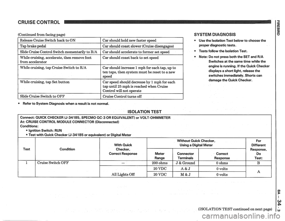
CRUISE CONTROL 2
I Slide Cruise Control Switch momentaril~ to RIA I Car should accelerate to former set s~eed I
(Continued from facing page)
--
While cruising, accelerate, then remove foot I car should coast back to set speed
from accelerator
Release Cruise Switch
back to ON
Tap brake pedal
I While cruising, tap Cruise Switch to RIA I Car should increase 1 mph for each tap, up to I
Car should hold new faster speed
Car should coast slower (Cruise disengages)
tap
until 25 mph is reached when cruise
Control will not o~erate I
While cruising, tap Set button
1 Slide Cruise Switch to OFF ten
taps, then system must be reset to a new
speed
Car speed should decrease by
1 mph for each
I Cruise Control turns off 1
0 Refer to System Diagnosis when a result is not normal.
SYSTEM DIAGNOSIS
@ Use the isolation Test below to choose the
proper diagnostic tests.
@ Tests follow the Isolation Test.
Note: Do not press both the SET and RIA
Switches at the same time while the
engine is running. If the Quick Checker
displays
a short light, release the
switches immediately. Shorts can
damage the Quick Checker.
lSOLATlON TEST
Connect: QUICK CHECKER (J-34185, SPECMO QC-3 OR EQUIVALENT) or VOLT-OHMMETER
At: CRUISE CONTROL MODULE CONNECTOR (Disconnected)
Conditions:
@ Ignition Switch: RUN
Test with Quick Checker
(J-34185 or equivalent) or Digital Meter
Test Condition
Cruise Switch OFF
(ISOLATION TEST continued on next page)
All Lights Off
With Quick
Checker,
Correct Response
-
20 VDC
20 VDC
For
Different
Response, Do
Test:
B
Without Quick Checker,
Using a Digital Meter
A&J
M&J
Meter
Range
200 ohms
0 volts
0 volts
Connector
Terminals
J & Ground
A
Correct
Response
0 ohms