1988 PONTIAC FIERO brake
[x] Cancel search: brakePage 727 of 1825
6E3-(31-8 2.8L (VIN S) DRIVEABILITY AND EMISSIONS
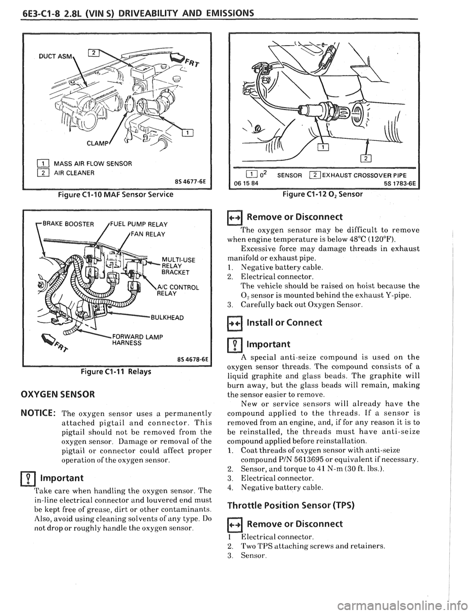
( MASS AIR FLOW SENSOR
Figure C1-10 MAF Sensor Service
BRAKE BOOSTER FUEL PUMP RELAY
/ /FAN RELAY
FORWARD LAMP
/ BULKHEAD
Figure C1-I I Relays
OXYGEN SENSOR
NOTICE:
The oxygen sensor uses a permanently
attached pigtail and connector. This
pigtail should not be removed from the
oxygen sensor. Damage or removal of the
pigtail or connector could affect proper
operation of the oxygen sensor.
Important
Take care when handling the oxygen sensor. The
in-line electrical connector and louvered end must
be kept free of grease, dirt or other contaminants.
Also, avoid using cleaning solvents of any type.
Do
not drop or roughly handle the oxygen sensor.
EXHAUST CROSSOVER PIPE
Figure C1-12 0, Sensor
Remove or Disconnect
The oxygen sensor may be difficult to remove
when engine temperature is below 48°C (120°F).
Excessive force may damage threads in exhaust
manifold or exhaust pipe.
~
1. Negative battery cable.
2. Electrical connector.
The vehicle should be raised on hoist because the
0, sensor is mounted behind the exhaust Y-pipe.
3. Carefully
back out Oxygen Sensor.
Install or Connect 1 i
Important I I
A special anti-seize compound is used on the
oxygen sensor threads. The compound consists
of a
liquid graphite and glass beads. The graphite will
burn away, but the glass beads will remain, making
the sensor easier to remove.
New or service sensors will already have the
compound applied to the threads. If a sensor is
removed from an engine, and, if for any reason it is to
be reinstalled, the threads must have anti-seize
compound applied before reinstallation.
1. Coat threads of oxygen sensor with anti-seize
compound
PIN 5613695 or equivalent if necessary.
2. Sensor, and torque to 41 N-m (30 ft. Ibs.).
3. Electrical connector.
4. Negative battery cable.
Throttle Position Sensor (TPS)
a Remove or Disconnect
1 Electrical connector.
2. Two 'I'PS attaching screws and retainers.
3. Sensor.
Page 729 of 1825
6E3-C1-10 2.8L (VIN 5) DRIVEABILITY AND EMISSIONS
- 959 DK GRN
BRAKE SWITCH
MANUALTRANS
TO FAN
CONTROL +-- DK GRNMIHT335 - COOLING FAN
RELAY
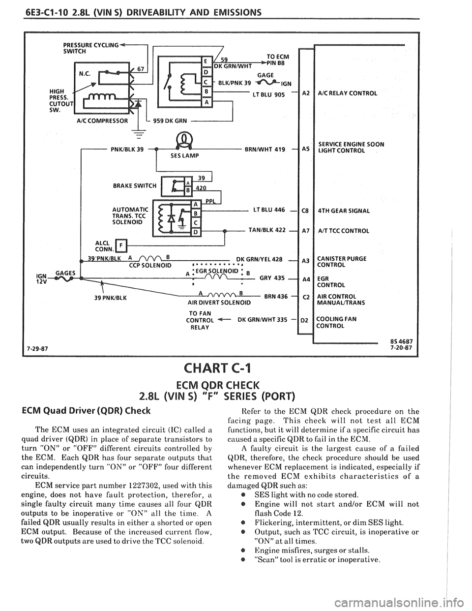
CHART C-I
ECM QDR CHECK
2.8% (VIN S) 'TI' SERIES (PORT)
ECM Quad Driwer (QDR) Check
The ECM uses an integrated circuit (IC) called a
quad driver
(QDR) in place of separate transistors to
turn "ON" or "OFF" different circuits controlled by
the ECM. Each
QDR has four separate outputs that
can independently turn "ON" or "OFF" four different
circuits.
ECM service part number 1227302, used with this
engine, does not have fault protection, therefor,
a
single faulty circuit many time causes all four QDR
outputs to be inoperative or "OX" all the time.
A
failed QDR usually results in either a shorted or open
ECM output. Because of the increased current
flow,
two QDR outputs are used to drive the TCC solenoid. Refer
to the ECM QDR check procedure on the
facing page. This
check will not test all ECM
functions, but it will determine if a specific circuit has
caused a specific
QDR to fail in the ECM.
A faulty circuit is the largest cause of a failed
QDR, therefore, the check procedure should be used
whenever ECM replacement is indicated, especially if
the removed ECM exhibits characteristics of a
damaged QDR such as:
@ SES light with no code stored.
@ Engine will not start and/or ECM will not
flash Code 12.
@ Flickering, intermittent, or dim SES light.
@ Output, such as TCC circuit, is inoperative or
"ON" at all times.
@ ISngine misfires, surges or stalls.
@ "Scan" tool is erratic or inoperative.
Page 752 of 1825
DRIVEABILITY AND EMISSIONS 2.8L (VIN 5) 6E3-C2-17
FUEL PUMP RELAY
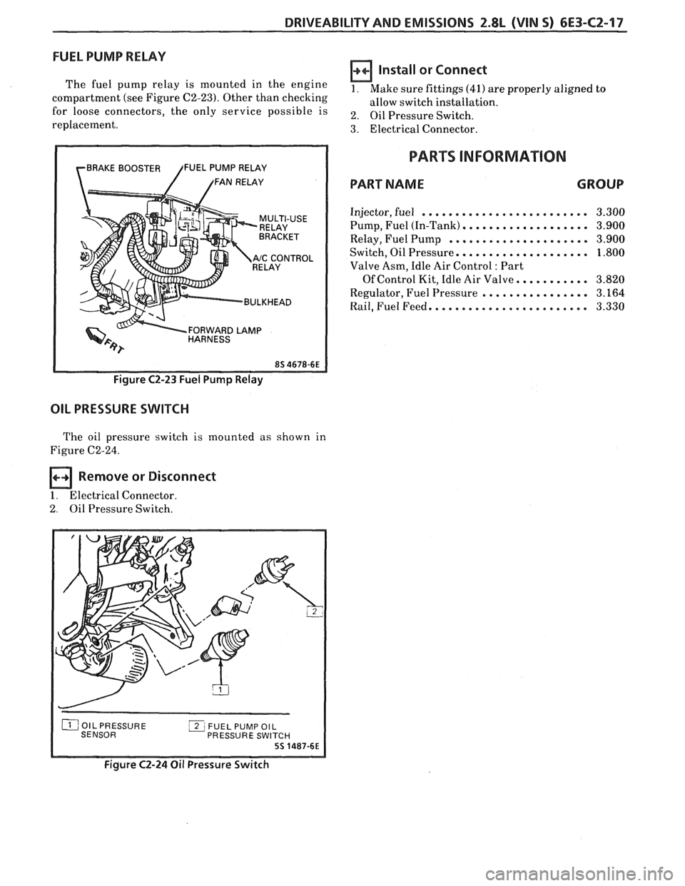
The fuel pump relay is mounted in the engine
compartment (see Figure C2-23). Other than checking
for loose connectors, the only service possible is
replacement.
rBRAKE BOOSTER /FUEL PUMP RELAY
/ /FAN RELAY
RELAY
Y '"ccONT"L
BULKHEAD
FORWARD
LAMP HARNESS
Figure C2-23 Fuel Pump Relay
OIL PRESSURE SWITCH
The oil pressure switch is mounted as shown in
Figure C2-24.
Remove or Disconnect
1. Electrical Connector.
2. Oil Pressure Switch.
Install or Connect
1. Make sure fittings (41) are properly aligned to
allow switch installation.
2. Oil Pressure Switch.
3. Electrical Connector.
PARTS INFORMATION
PART NAME GROUP
Injector, fuel ......................... 3.300
Pump, Fuel (In-Tank)
................... 3.900
Relay, Fuel Pump
..................... 3.900
Switch, Oil Pressure.
................... 1.800
Valve Asm, Idle Air Control
: Part
Of Control Kit, Idle Air Valve.
.......... 3.820
Regulator, Fuel Pressure
................ 3.164
Rail, Fuel Feed. ....................... 3.330
PRESSURE SWI
Figure C2-24 Oil Pressure Switch
Page 786 of 1825
DRIVEABILITY AND EMlSSlONS 2.8L (VIN %I 6E3-C8-1
TRANSMISSION CONVERTER CLUTCH (KC) SYSTEM
AND MANUAL
TRANSMISSION SHIFT LIGHT
CONTENTS
GENERAL DESCRIPTION ................ C8-1 DIAGNOSIS ..........ee...ee....e.e. C8-1
PURPOSE ......................... C8-1 SHIFT LIGHT (MIT) DESCRIPTION ........ C8-1
OPERATION ....................... C8-1 DIAGNOSIS ....................... .. C8-1
ON-CAR SERVICE ...................*. C8-1
GENERAL DESCRIPTION
PURPOSE
The transmission converter clutch (TCC) svstem
uses a solenoid operated valve in the automatic
transmission to couple the engine flywheel to the
output shaft of the transmission thru the torque
converter. This reduces the slippage losses in the
converter, which increases fuel economy.
OPERATION
For the converter clutch to apply, two conditions
must be met:
o Internal transmission fluid pressure must be
correct. For information on internal transmission
operation, see Section
"7A". This section will cover
only the electrical operation of the TCC system.
@ The ECM grounds a switch internally to turn on a
solenoid in the transmission. This moves a check
ball, which will allow the converter clutch to
apply, if the hydraulic pressure is correct, as
described above.
The ECM controls the TCC apply solenoid by
looking at several sensors:
@ Speedo Buffer Sensor (also called vehicle speed
sensor
(VSS). Speed must be above a certain value
before the clutch can apply.
@ Coolant Temperature Sensor. Engine must be
warmed up before clutch can apply about
65OC
(149°F').
Throttle position sensor ('I'PS). After the
converter clutch applies, the
HCM uses the
information from the TPS to release thc clutch
when the car is accelerating or decelerating at a
certain rate.
@ 'I'he brake switch is also part of the 'I'CC circuit as
it will remove battery voltage to the 'KC solenoid
when the brake pedal is depressed.
@ Gear Select Switch. The 4th gear switch is used to
send a signal to the
ECM telling it when the
transmission is in 4th gear. The ECM uses this
information to vary the conditions under which
the clutch applies or releases.
IIowever, the
transmission does not have to be in fourth gear in
order for the ECM to turn the clutch on.
If the converter clutch is applied at all times. the
engine will stall immediately, just as in
u manual
transmission with the clutch applied.
If the converter clutch does not apply, fuel
ecomony
may be lower than expected. If the vehicle
speed sensor fails, the TCC will not apply. If the 4th
gear switch does not operate, the TCC may not apply
at the right time.
DIAGNOSIS
The diagnosis of the TCC system is covered in
CHART C-8
. If the ECM detects a problem in the
system,
a Code 24 should set. In this case see Code 24
CHART.
SHIFT LIGHT (MiT) DESCRIPTION
'The purpose of the shift light is to provide a
display which indicates the optimum fuel economy
point for up
shifling the manual transmission based
on engine speed
and load. 'I'he display is a lamp on the
instrument panel. Activation of the ECM driver turns
the lamp
on.
'I'he shift light circuit can he checlted using
CHAR?' C-8C.
ON-CAR SERVICE
@ See Section "8B" if the shift light bulb needs
replacement.
@ See Section "6E" to repair wiring problem.
@ See Section "6C" if ECM is to be replaced.
Page 809 of 1825
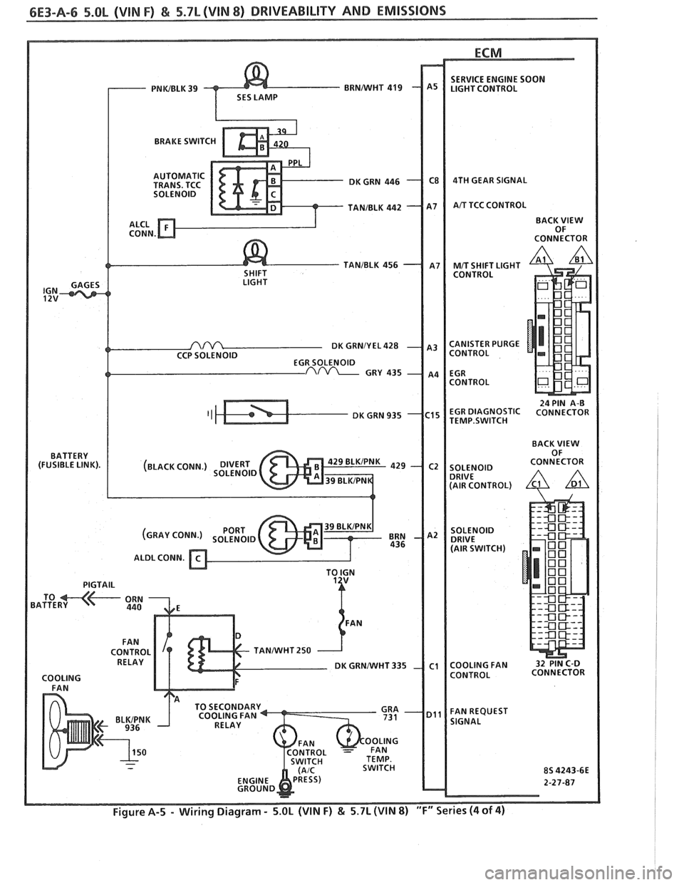
BRAKE SWITCH
TANIBLK 456
DK GRNIY EL 428
TEMP.SWITCH
TANNVHT 250
Page 894 of 1825
DRIVEABILITY AND EMISSIONS 5.OL (VIN F) & 5.7L (VIN 8) 6E3-C2-7
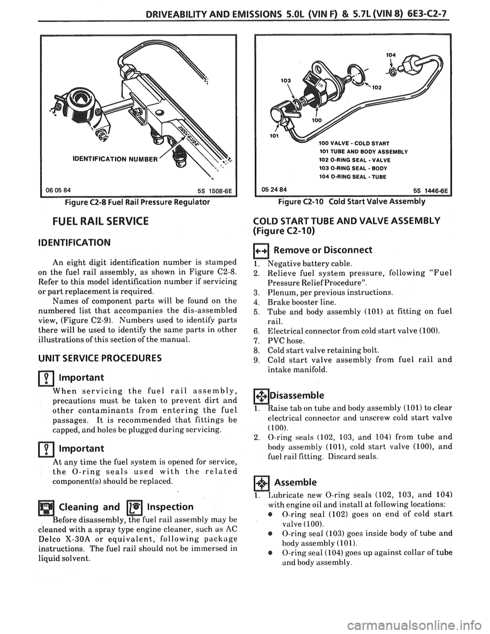
Figure C2-8 Fuel Rail Pressure Regulator
FUEL RAIL SERVICE
IDENTIFICATION
An eight digit identification number is stamped
on the fuel rail assembly, as shown in Figure C2-8.
Refer to this model identification number if servicing
or part replacement is required.
Names of component parts will be found on the
numbered list that accompanies the dis-assembled
view, (Figure C2-9). Numbers used to identify parts
there will be used to identify the same parts in other
illustrations of this section of the manual.
UNIT SERVICE PROCEDURES
lrnportant
When servicing the fuel rail assembly,
precautions must be taken to prevent dirt and
other contaminants from entering the fuel
passages. It is recommended that fittings be
capped, and holes
be plugged during servicing.
Important
At any time the fuel system is opened for service,
the
O-ring seals ised with the related
component(s) should be replaced.
Cleaning and Inspection
Before disassembly, the fuel rail assenlbly may be
cleaned with a spray type engine cleaner, such as
AC
Delco X-30A or equivalent, following
package
instructions. The fuel rail should not be immersed in
liquid solvent.
0 VALVE - COLD START
101 TUBE AND BODY ASSEMBLY
102 O-RING SEAL
- VALVE
103 O-RING SEAL
- BODY
104 O-RING SEAL -TUBE
Figure CZ-10 Cold Start Valve Assembly
COLD START TUBE AND VALVE ASSEMBLY
(Figure
CZ-I 0)
Remove or Disconnect
1. Negative battery cable. -
Relieve fuel system pressure, following "Fuel
Pressure Relief Procedure".
Plenum, per previous instructions.
Brake booster line.
Tube and body assembly (101) at fitting on fuel
rail.
Electrical connector from cold start valve (100).
PVC hose.
Cold start valve retaining bolt.
Cold start valve assembly from fuel rail and
intake manifold.
+$ Disassemble
1. Raise tab on tube and body assembly (101) to clear
electrical connector and unscrew cold start valve
(100).
2. O-ring seals (102, 103, and 104) from tube and
body assembly
(lOl), cold start valve (loo), and
fuel rail fitting. Discard seals.
1. Lubricate
new O-ring seals (102, 103, and 104)
with engine oil and install at following locations:
@ O-ring seal (102) goes on end of cold start
valve
(100).
@ O-ring seal (103) goes inside body of tube and
body assembly
(101).
@ O-ring seal (104) goes up against collar of tube
and body assembly.
Page 896 of 1825
DRIVEABILITY AND EMISSIONS 5.OL (VIN F) & 5.7L (VIN 8) 6E3-CZ-9
Cold start valve (100) onto tube and body
assembly
.
Screw in until valve bottoms. then back off
until hole in mounting lug on valve will be
aligned properly with hole in fuel rail when
mounted
.
@ Bend tang over cold start valve to lock it in
position
.
Clean
@ Areas around valve and connection with AC
Delco X-30A or equivalent
.
Install or Connect
1 . Cold start (100) valve in intake manifold .
2 . Cold start valve retaining bolt .
Tighten
@ Retaining bolt to 27 Nwm (20 ft . lbs.). .
3 . PVC hose .
4 . Tube and body assembly (101) at fitting on fuel
rail
.
Tighten
@ Nut on fitting to 27 N-m (20 ft . lbs.).
6 . Brake booster line .
6 . Electrical connector on cold start valve (100)
7 . Negative battery cable .
Inspect
@ Energize fuel pump and inspect for leaks .
8 . Intake manifold plenum. per previous
instructions
.
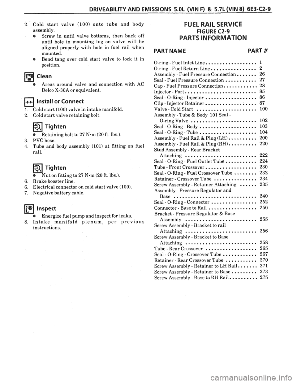
FUEL RAIL SERVICE
FIGURE CZ-9
PARTS INFORMAION
PART NAME PART #
. .................. O-ring Fuel Inlet Line 1
. ................ O-ring Fuel Return Line 2
Assembly
. Fuel Pressure Connection ....... 26
Seal
. Fuel Pressure Connection ........... 27
Cap
. Fuel Pressure Connection ............ 28
Injector
. Port ......................... 85
. . .................. Seal 0-Ring Injector 86
. .................. Clip Injector Retainer 87
. ..................... Valve Cold Start 100
Assembly
. Tube & Body 101 Seal .
....................... O-ring Valve 102
. . .................... Seal 0-Ring Body 103
. . .................... Seal 0-Ring Tube 104
. .......... Assembly Fuel Rail & Plug (LH) 200
. .......... Assembly Fuel Rail & Plug (RH) 220
Stud Assembly
. Rear Bracket
......................... Attaching 222
Seal
. 0-Ring . Fuel Outlet Tube ........... 224
. ................. Tube Front Crossover 230
. . ........ Seal 0-Ring Fuel Crossover Tube 232
. .*............. Retainer Crossover Tube 234
...... . Screw Assembly Retainer Attaching 235
Assembly
. Pressure Regulator and
............................. Base 240
. ................ . Seal 0-Ring Connector 252
. ................. Connector Base to Rail 250
Bracket
. Pressure Regulator & Base
......................... Assembly 255
Screw Assembly
. Bracket to rail
......................... Attaching 256
Screw Assetnhly
. Bracket to Base
......................... Attaching 258
. .................. Tube Rear Crossover 265
. . ............ Seal 0-Ring Crossover Tube 267
........... . Retainer Rear Crossover Tube 270
....... . Screw Assembly Retainer to LH Rail 271
......... . Screw Assembly Retainer to Base 273
.......... . Screw Assembly Base to RH Rail 275
Page 903 of 1825
6E3-CZ-16 5.OL (VIN F) & 5.7L(VIN 8) DRIVEABILITY AND EMISSIONS
Tighten
- @ Screw assemblies to 3.0 Nem (27.0 in. lbs.).
4. IAC valve assembly (70). (See "Idle Air Control
Valve and Gasket" instructions).
NOTICE: Before installing the IAC valve assembly,
the position of its pintle
MUST be checked.
If pintle is extended too far, damage to the
assembly may occur. (See
"Idle Air
Control Valve and Gasket" instructions.)
FUEL PUMP RELAY
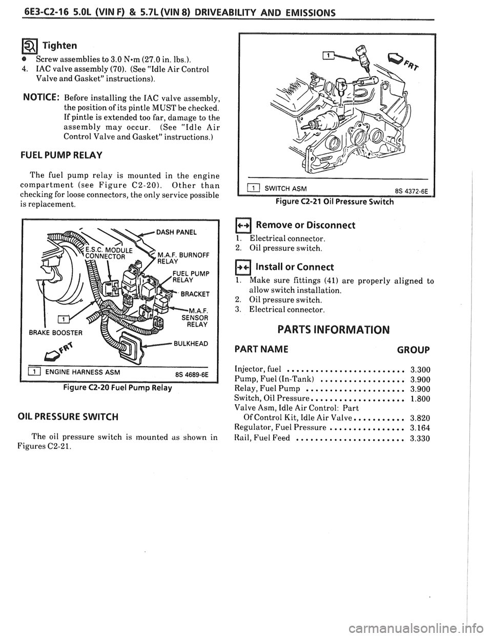
The fuel pump relay is mounted in the engine
compartment (see Figure
C2-20). Other than
checking for loose connectors, the only service possible
is replacement.
BRAKE BOOSTER
Figure C2-20 Fuel Pump Relay
OIL PRESSURE SWITCH
The oil pressure switch is mounted as shown in
Figures C2-2
1.
Figure C2-21 Oil Pressure Switch
a Remove or Disconnect
I. Electrical connector.
2. Oil pressure switch.
Install or Connect
1. Make sure fittings (41) are properly aligned to
allow switch installation.
2. Oil pressure switch.
3. Electrical connector.
PARTS INFORMATION
PART NAME GROUP
Injector, fuel ......................... 3.300
Pump, Fuel (In-Tank)
.................. 3.900
Relay, Fuel Pump
..................... 3.900
Switch, Oil Pressure,
................... 1.800
Valve Asm, Idle Air Control: Part
Of Control Kit, Idle Air Valve. .......... 3.820
Regulator, Fuel Pressure
................ 3.164
Itail, Fuel Feed ....................... 3.330