1988 PONTIAC FIERO brake
[x] Cancel search: brakePage 1118 of 1825
AUTOMATIC TRANSMISSION 7A-3
PRELIMARY CHECKING PROCEDURE
The condition of an automatic transmission not
operating properly may be influenced by one, or a
combination of the following items:
e Fluid level high/low
(Refer to Section 7A1)
e Engine performance
(Refer to Sections 6 and 6E)
T.V. cable adjustment
(Refer to Section
7A1)
e Manual linkage adjustment
(Refer to Section
7A1)
e Internal fluid leaks
(Refer to Transmission Unit Repair section)
e Electrical system
(Refer to Section 6E and 8A)
e Transmission or other mechanical component
(Refer to Transmission Unit Repair section)
e Vacuum modulator
(Refer to appropriate Hydraulic Diagnosis
Section)
NOISE AND VIBRATION ANALYSIS
A noise or vibration that is noticeable when the
vehicle is in motion, MAY NOT be the result of the
transmission.
If noise or vibration is noticeable in "Park"
(P)
and "Neutral" (N) with engine at idle, but is less
noticeable as
RPM's increase, the cause may be from
poor engine performance.
e Tires for
- Uneven wear
- Imbalance
- Mixed sizes
- Mixed radial and bias ply
(Refer to Section 3E)
e Suspension components for
- Alignment and wear
- Loose fasteners
(Refer to Section 3C)
e Engine/Transmission mounts for
- Damage
- Loose bolts
(Refer
to Sections 6A and 7A2)
e Transmission case mounting holes for:
- Missing bolts, nuts, studs
- Stripped threads
- Cracks
e Flywheel for:
- Missing or loose bolts
- Cracks
- Imbalance
(Refer to Section 6A)
e Torque converter for: - Missing or loose bolts or lugs - Missing or loose balance weights
- Imbalance
TRANSMISSION FLUID LEVEL INFORMATION
Checking fluid level, color and condition at
regular intervals will provide early diagnosis
information about the transmission. This information
may then be used to correct a condition that, if not
detected early, could result in major transmission
repairs.
When adding or changing fluid, use only
DEXRONO 11, or equivalent. Refer to Section OB of
this Service Manual for maintenance information and
servicing intervals.
Fluid level should be checked when it reaches
normal operating temperatures of
190-200°F.
(88-93°C). This temperature is reached after
approximately 15 miles (24 km) of highway
driving.
e Fluid color - Should be dark red (may be dark green)
NOTICE: Do not overfill. Overfilling will cause
foaming, loss of fluid and possible damage to the
transmission.
Inaccurate fluid level readings will result if
checked immediately after the vehicle has been
operated:
- In high abmient temperatures above 90°F
(32°C)
- At sustained high speeds
- In heavy city traffic during hot weather
- As a towing vehicle - In commercial service (taxi or police use)
TRANSMISSION FLUID CHECKING
PROCEDURE
(Refer to Figure 3)
1. Park vehicle on level ground.
2. Apply parking
brake and block wheels.
3. Start
engine and operate vehicle for 15 minutes or
until a normal operating temperature is reached.
4. Move gear
selector through all gear positions.
5. Move
gear selector to "Park" (P).
6. Check fluid level, color and condition.
Page 1122 of 1825
AUTOMATIC TMNSMISSION ON-VEHICLE SERVICE 7A1-3
e Propeller shaft oil seal worn or damaged
o Governor cover
e Line pressure pipe plug loose
@ Porous casting
3. Leak at converter end:
Converter seal damaged
- Seal lip cut. (Check converter hub for
damage.)
- Bushing moved forward and damaged
- Garter spring missing from seal
o Converter leak in weld area. (Refer to
Torque Converter.)
Porous casting (Case or pump)
4. Fluid comes out vent pipe or fill tube:
Over-filled
Water or coolant in fluid. Fluid will appear
milky.
e Case porous
e Incorrect fluid level indicator
e Plugged vent
e Drain back holes plugged
Mispositioned oil pump to case gasket (if
equipped)
Case Porosity Repair
1. Clean the leak area with solvent and air dry.
CAUTION: Epoxy adhesive may cause
skin irritations and eye damage. Read
and follow all information on the
container label as provided by the
manufacturer.
2. Mix a sufficient amount of epoxy adhesive,
# 1052533, or equivalent, following the
manufacturer's recommendations.
3. While the transmission case is hot, apply epoxy
adhesive with a clean, dry soldering acid brush.
4. Allow the epoxy adhesive to cure for three hours
before starting the engine.
5. Repeat fluid leak diagnosis procedures.
TORQUE CONVERTER CLUTCH ELECTRICAL
CONTROLS
The Torque Converter Clutch (TCC) system uses
controls that are internal as well as external to the
transmission. For internal control components of the
TCC system, refer to the I-Iydraulic Diagnosis Section
for for wiring diagrams and switch locations.
The external control components of the TCC
system include:
1. Brake Release Switch - To avoid stalling the
engine when braking, the converter clutch is
released any time the brakes are applied.
2. Electronic Control ModuOe - Receives input
signals and grounds TCC solenoid to apply clutch
when proper operating conditions are met.
3. Throttle Position Sensor - Sends throttle
position information to Electronic Control
Module.
4. Vacuum Sensor - Sends engine vacuum (load)
information to Electronic Control Module.
5. Vehicie Speed Sensor - Sends vehicle speed
information to Electronic Control Module.
6. Coolant Temperature Sensor - Sends engine
coolant temperature information to Electronic
Control Module.
TORQUE CONVERTER CLUTCH DIAGNOSIS
To properly diagnose the Torque Converter
Clutch (TCC) system perform all electrical testing first
and then the hydraulic testing. Refer to the appropriate
Driveability and Emissions Section (6E) for additional
Torque Converter Clutch Information
ON-VEHICLE SERVICE
SI-IIFT CONTROL CABLE
Remove or Disconnect (Fig. 1)
1. Negative battery cable.
2. Raise car, see Section OA.
3. Cable attachments at transmission.
4. Lower car.
5. Console, see Section
8C.
6. Cable at control lever and base.
7. Cable from floor.
install or Connect
1. Cable to floor.
2. Cable at base and control lever.
3. Console, see Section 8C.
4. Place control lever in "NEUTRAL"
5. Raise car.
6. Cable attachments at transmission.
7. Adjust cable.
8. Lower car.
9. Negative battery cable.
Adjust (Fig. 1)
1. Place control lever in "N" (Neutral).
2. Raise car, see Section 0.4.
3. Loosen cable
attachment at shift lever.
4. Rotate shift lever "clockwise" to park detent and
then back to neutral.
5. Tighten cable attachment.
15
N-m (11 lbs. ft.)
Important
Levg must be held out of "PARK" when
torquing nut.
6. Lower car.
7. Check cable adjustment by rotating control lever
thru the detents.
Remove or Disconnect (Fig. 2)
1. Negative battery cable.
2. Console, see Section 8C.
3. Cable at control lever and base.
Page 1125 of 1825
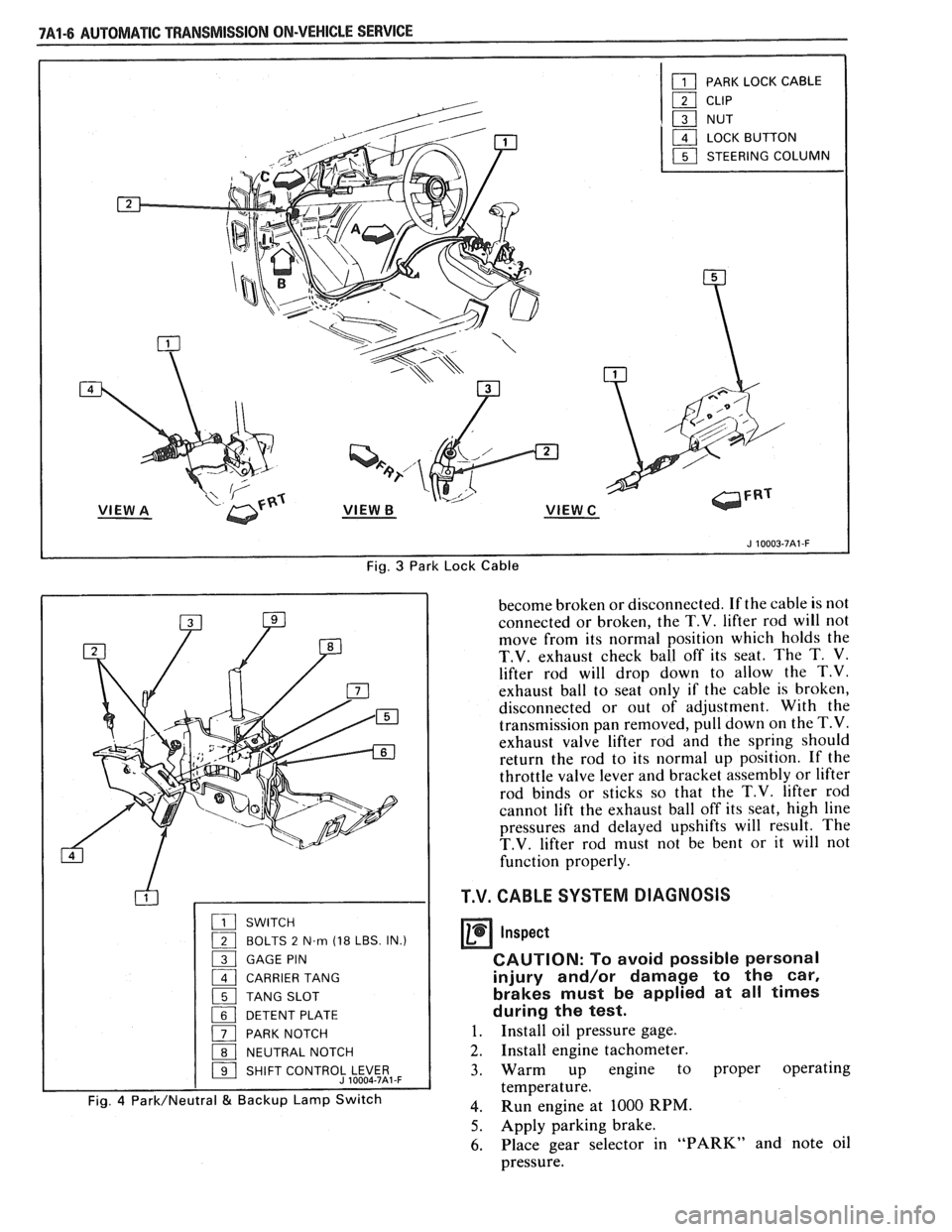
Fig. 3 Park Lock Cable
SWITCH
( BOLTS 2 N.m (18 LBS. IN.)
1 GAGE PIN
1 CARRIER TANG
1 TANG SLOT
1 DETENT PLATE
( PARK NOTCH
1 NEUTRAL NOTCH
1 SHIFT CONTROJLE$5t,-F
Fig. 4 Park/Neutral & Backup Lamp Switch
become broken or disconnected. If the cable is not
connected or broken, the
T.V. lifter rod will not
move from its normal position which holds the
T.V. exhaust check ball off its seat. The T. V.
lifter rod will drop down to allow the T.V.
exhaust ball to seat only if the cable is broken,
disconnected or out of adjustment. With the
transmission pan removed, pull down on the
T.V.
exhaust valve lifter rod and the spring should
return the rod to its normal up position. If the
throttle valve lever and bracket assembly or lifter
rod binds or sticks so that the
T.V. lifter rod
cannot lift the exhaust ball off its seat, high line
pressures and delayed upshifts will result. The
T.V. lifter rod must not be bent or it will not
function properly.
T.V. CABLE SYSTEM DIAGNOSIS
Inspect
CAUTION: To avoid possible personal
injury and/or damage to the car,
brakes must be applied at all times
during the test.
1. Install oil pressure gage.
2. Install engine tachometer.
3. Warm up engine to proper operating
temperature.
4. Run engine at 1000 RPM.
5. Apply parking brake.
6. Place gear selector in "PARK" and note oil
pressure.
Page 1158 of 1825
CLUTCH 7C-4
SECTION 76
CLUTCH
CONTENTS
GENERAL DESCRIPTION .......................... .. ............................................................. 7C-I
DIAGNOSIS ...................................................................................................................... 7C-3
Preliminary Checks ....................... ... ............................................................................ 7C-2
Bleeding Hydraulic Clutch System ................... .. .......................................................... 7C-2
ON-VEHICLE SERVICE ................................................................................................. 7C-5
Clutch Hydraulic System ................................................................................................. 7C-5
..................... Pressure Plate and Disc .. ........................................................................... 7C-6
Clutch Pedal ..................................................................................................................... 7C-6
Pilot Bearing .................................................................................................................. 7C-6
....................................................................................................... SPECIFICATIONS 7C-8
............................................................................................................ SPECIAL TOOLS 7C-8
GENERAL DESCRIPTION
COMPONENTS
The principal parts of a clutch system are: the
driving member and the operating members. Figure
7C-1 shows an exploded view of the clutch system.
DRIVEN MEMBERS (FIGURES 7C-1 AND 7C-2)
The driven member is the clutch disc with a
splined hub which is free to slide lengthwise along the
splines of the input shaft, but which drives the input
shaft through these same splines.
The driving and driven members are held in
contact by spring pressure. This pressure is exerted by
a diaphragm spring in the pressure plate assembly.
HYDRAULIC CLUTCH (FIGURE 7C-3)
A hydraulic clutch operating mechanism is used
on all models. The
mechanism consist of a remote
reservoir, clutch master cylinder and slave cylinder.
The remote reservoir is mounted to a bracket which
bolts to the power brake booster. The clutch master
cylinder is mounted on the cowl panel and the slave
cylinder is mounted on the bell housing. The clutch
master cylinder is operated directly off the clutch
pedal.
When the clutch pedal is pressed down, hydraulic
fluid under pressure from the clutch master cylinder
flows into the slave cylinder. Since the piston is also
connected to the clutch fork this lever moves the
release bearing into contact with the clutch cover
release fingers to disengage the clutch. The hydraulic
clutch system locates the clutch pedal height and
provides automatic clutch adjustment. No adjustment
of clutch linkage or pedal position is required.
OPERATING MEMBERS (FIGURE 7C-3)
HYDRAULIC CLUTCH FLUID
When adding fluid to or refilling the system after
The clutch release system is operated by service operations use GM Delco Supreme No. 11 hydraulic pressure and consists of the clutch pedal, brake fluid or an equivalent fluid that meets DOT 3 clutch master cylinder, clutch slave cylinder, clutch specifications. fork and clutch release bearing.
NOTICE: Do not use mineral or paraffin base oil in
the Clutch Hydraulic System. These fluids will
damage the rubber parts in the cylinders.
Page 1159 of 1825
7C-2 CLUTCH
PRELIMINARY CHECKS
Before attempting to repair the clutch,
transmission or related hydraulic components for any
reason other than
an obvious failure, the problem and
probable cause should be identified.
A large percentage
of clutch and manual transmission
problenls are
manifested by shifting difficulties such as high shift
effort, gear clash and grinding or transmission
blockout. When any of these problems occur, a careful
analysis of these difficulties should be accomplished
and the following checks and adjustments performed
in the presented sequence before removing the clutch
or transmission for repairs.
Before
removal of the clutch hydraulic system,
verify the malfunction by renloving the clutch housing
dust shield and
measure the travel of the clutch slave
cylinder push rod. With clutch pedal pushed fully to
the floor, the
slave cylinder push rod should extend
14.53mm (0.57 inch) minimum against the clutch
release lever. Do
not replace the hydraulic system if
push rod travel exceeds this distance.
If slave cylinder does not meet the travel require-
ments, check the reservoir fluid level. The slave cylinder
must be in place when checking the fluid level. The proper
level is indicated by a step on the reservoir. Fill to the
specified level with
GM Delco Supreme No. 11 Brake
Fluid or an equivalent fluid that meets DOT
3 specifica-
tions. Do not overfill. The upper portion of the reservoir
must accept fluid that is displaced from the slave cylinder
as the clutch wears.
NOTICE: Carefully clean the top and sides of the
reservoir before opening to prevent contamination of
the system with dirt, water or other foreign material.
Remove the reservoir diaphragm before adding fluid.
Carefully replace the diaphragm, cover gasket and
cover after filling.
If the reservoir requires any fluid, check the
hydraulic system components for leakage. Remove the
rubber boots from the cylinder and check for leakage
past the pistons. A slight wetting of the surfaces is
acceptable. Replace the system, if excessive leakage is
evident.
BLEEDING CLUTCH SYSTEM
allowed to fall so low that air has been drawn into the
master cylinder.
NOTICE: Never, under any circumstances, use
fluid which has been bled from a system to fill the
reservoir as it may be aerated, have too much
moisture content and possibly be contaminated.
Clean dirt and grease from the cap to ensure no
foreign substances enter the system.
Remove cap and diaphragm and
fill reservoir to
the top with approved brake fluid only. (Brake
fluid must be certified to DOT 3 specifications).
Fully loosen bleed screw which is in the slave
cylinder body next to the inlet connection.
Fluid will now begin to move from the master
cylinder down the tube to the slave. It is
important that for efficient gravity
fill, the
reservoir must be kept full at all times.
It will be noticeable at this point that bubbles will
appear at the bleed screw outlet. This means that
air is being expelled. When the slave is full, a
steady stream of fluid will come from the slave
outlet. At this point tighten bleed screw to a
torque of 2
N .m.
Assemble diaphragm and cap to the reservoir,
fluid in reservoir should be level with step.
Exert a light load (approximately 20 lbs.) to the
slave cylinder piston by pushing release lever
towards the cylinder and loosen bleed screw.
Maintain a constant light load, fluid and any air
that is left will be expelled through the bleed port.
Tighten bleed screw when a steady flow of fluid
and no air is being expelled.
Renew fluid level in reservoir, assemble
diaphragm and cap. If necessary, repeat Steps
7
and 8.
Exert light load to release lever as in Step 7 (do
not open bleed screw), piston in slave will move
slowly down bore. Repeat 2-3 times, fluid
n~oven~ent will force any air left in the system into
the reservoir.
The hydraulic system should now be fully bled
and should release the clutch. Check vehicle by
starting, pushing clutch pedal to the floor and
selecting reverse gear. There should be no grating
of gears, if there is, the hydraulic system could
still contain air. If this is the case, repeat bleed
The process of removing air from the
line and procedure.
cylinders is known as "bleeding" and is necessary Check push rod travel at the
slave cylinder to insure
whenever the level of fluid in the reservoir has been the minimum travel
of
14.53mm (0.57 inch) for V-8
and 1 lrnm (0.43 inch) for V-6.
Page 1162 of 1825
CLUTCH 7C-5
Grabbing (Chattering)
Rattling
- Transmission
Click
Release Bearing Noise
with Clutch Fully
Engaged
Noisy
Pedal Stays on Floor
When Disengaged heated.
a. Oil
on facing. Burned
or glazed facings.
b. Worn splines
on
clutch gear.
c. Warped pressure
plate or flywheel.
d. Burned or smeared
resin on flywheel or
pressure plate.
a. Weak retracting
springs.
b. Release fork loose
on ball stud or in bear-
ing groove.
c. Oil in driven plate
damper.
d. Driven plate damper
spring failure.
a. Release bearing bind-
ing on transmission
bearing retainer.
b. Fork improperly in-
stalled. a. Worn release bearing.
b. Fork off ball stud
(heavy clicking).
c. Pilot bearing loose
in crankshaft.
a. Bind in release
bearing.
b. Springs weak in
pressure plate. a.
Install new disc and
correct leak.
b. Replace transmission
clutch gear.
c. Replace pressure plate
or flywheel.
d. Sand off if superficial,
replace burned or heat
checked parts.
a. Replace pressure plate.
b. Check ball stud and
retaining.
c. Replace driven disc.
d. Replace driven disc.
a. Clean, relubricate,
check for burrs, nicks,
etc.
b. Install properly.
a. Replace bearing.
b. Install properly and
lubricate fork fingers
and bearing.
c. See Section
6 for
bearing fits.
Lubricate and free-up
release bearing.
b. Replace pressure
plate.
ON-VEHICLE SERVICE
CLUTCH HYDRAULIC SYSTEM 7. Remove the clutch fluid reservoir from bracket.
NOTICE: The clutch hydraul~c 4ystern is serviced 8. Pull brake niaster cylinder forward for access to
as a complete unit, it has been bled
of air and filled clutch master cylinder.
with fluid. Individual components of the system 9. Remove the clutch master cylinder from cowl.
are
not available separately. 10. Hoist vehicle.
1 1. Remove the slave cvlinder heat shield.
Prior to any vehicle service that requires removal of
the slave cylinder
(i.e., transmission and clutch housing
removal), the
master cylinder push rod must be
disconnected from the clutch pedal. If not discon-
nected, permanent damage to the slave cylinder will
occur if the clutch pedal is depressed while the slave
cylinder is disconnected.
Removal
1. Disconnect negative battery cable.
2. Remove the steering column trim cover.
3. Remove the hush panel.
4. Discoonect the master cylinder push rod from
clutch pedal.
5. Remove the clutch master cylinder to cowl nuts.
6. Remove the brake booster to cowl nuts.
12. Remove the slave cylinder from bell housing.
13. Lower vehicle.
14. Remove the clutch hydraulic system from engine
compartment.
Installation
1. Position
hydraulic clutch master cylinder at cowl
and feed slave cylinder drown to bell housing
area.
2. Pilot clutch master cylinder push rod through
cowl and position master cylinder to cowl with
U
bolt.
3. Connect brake booster to cowl.
4. Pilot clutch master cylinder
U bolt through
clutch braces and torque nuts.
5. Torque brake master cylinder to cowl nuts.
Page 1163 of 1825
7C-6 CLUTCH
6. Clutch master cylinder push rod to clutch pedal.
7. Install brake switch.
8. Install hush panel.
9. Install steering column trim cover.
10. Install clutch reservoir to bracket.
1 1. Hoist vehicle.
12. Pilot slave cylinder into clutch fork.
NOTICE: With a new system, the slave cylinder
contains a shipping strap that pre-positions the
push rod for installation, and also provides a
bearing insert.
Follojving installation of the slave
cylinder, the first actuation of the clutch pedal will
break the shipping strap and give
normal system
operation.
13. Install slave cylinder and heat shield to bell
housing.
14.
Lojver vehicle.
15. Connect negative battery cable.
CLUTCH ASSEMBLY
Removal
1. Remove the transmission as outlined in
transmission section.
2. Remove the slave cylinder heat shield and slave
cylinder
from flywheel housing.
3. Reniove the flywheel housing.
4. Slide clutch fork from ball stud and remove fork
from dust boot. Ball stud is threaded into clutch
housing and is easily replaced, if necessary.
5. Install Tool 5-33169 to support the clutch
assen~bly during removal. Look for mark or white
painted letter on clutch cover and
"X" mark on
flywheel. If
"Xu or letter is not evident, mark
flywheel and clutch cover for indexing purposes
during installation.
6. Loosen clutch-to-flywheel attaching bolts evenly
1 turn at a time until spring pressure is released.
7. Remove clutch and pressure plate assembly.
lnspection
Inspect the flywheel for cracks, heat checking or
other defects. Replace or repair as required.
Installation
Pressure plate and flywheel face, (They should be
free of oil, grease, metal deposits or burned spots.)
Installation
1. Position clutch disc and pressure plate in relative
installed position and support them with
alignment Tool J-33169 or a drive gear.
The driven disc is installed with the damper
springs to the transmission. The flywheel side is
marked.
2. Turn clutch assembly until "X" mark or white
painted letter on cover lines up with
"X" mark on flywheel,
then align cover bolt holes to nearest
flywheel holes.
3. Install a bolt in every hole and tighten down
evenly and gradually until tight to avoid possible
clutch distortion. (Cover loads are as high as
1- 1/4 tons).
4. Remove the pilot tool.
5. Unhook clutch fork and lubricate ball socket and
fork fingers at release bearing end with a high
melting point grease such as graphite and
reinstall fork on ball stud.
6. Lubricate recess on inside of release bearing
collar and the clutch fork groove with light coat
of graphite grease. Refer to Figure 7C-6.
7. Install the clutch fork and dust boot into clutch
housing and install release bearing to fork, then
install flywheel housing.
8. Install the transmission as outlined in
transmission section.
9. Install the clutch slave cylinder and bracket.
CLUTCH PEDAL
Removal
Disconnect the negative cable at battery.
Remove the steering column trim cover.
Remove the hush panel from under dash.
If equipped, disconnect cruise control switch at
clutch pedal.
Disconnect the neutral start switch at clutch
pedal.
Renlove the turn signal and hazard flasher
mounting bracket attaching screws.
Disconnect the clutch master cylinder push rod
from pedal.
Remove the nut from clutch pedal pivot bolt. Pull
bolt out far enough for pedal removal.
Inspection
Clean and inspect all components and replace as
necessary. Do not clean bushings with a cleaning
solvent, simply wipe with a clean cloth.
Relubricate all bushings and moving parts.
Installation
1. Reverse the removal procedure.
PILOT BEARING (FIGURE 7C-7)
Replacement
The clutch pilot bearing is an oil impregnated type
bearing pressed into the crankshaft. This bearing requires
attention when the clutch is removed from the vehicle, at
which time it should be cleaned and inspected for exces-
sive wear or damage and should be replaced if necessary.
To remove, install Tool
J 23907 and remove bearing
from crankshaft, as shown in Figure
7C-7. In replacing
this bearing, use Tool
J 1522. Place bearing on pilot of
tool with radius in bore of bearing next to shoulder on tool
and drive into crankshaft. Lubricate with several drops of
machine oil.
Page 1164 of 1825
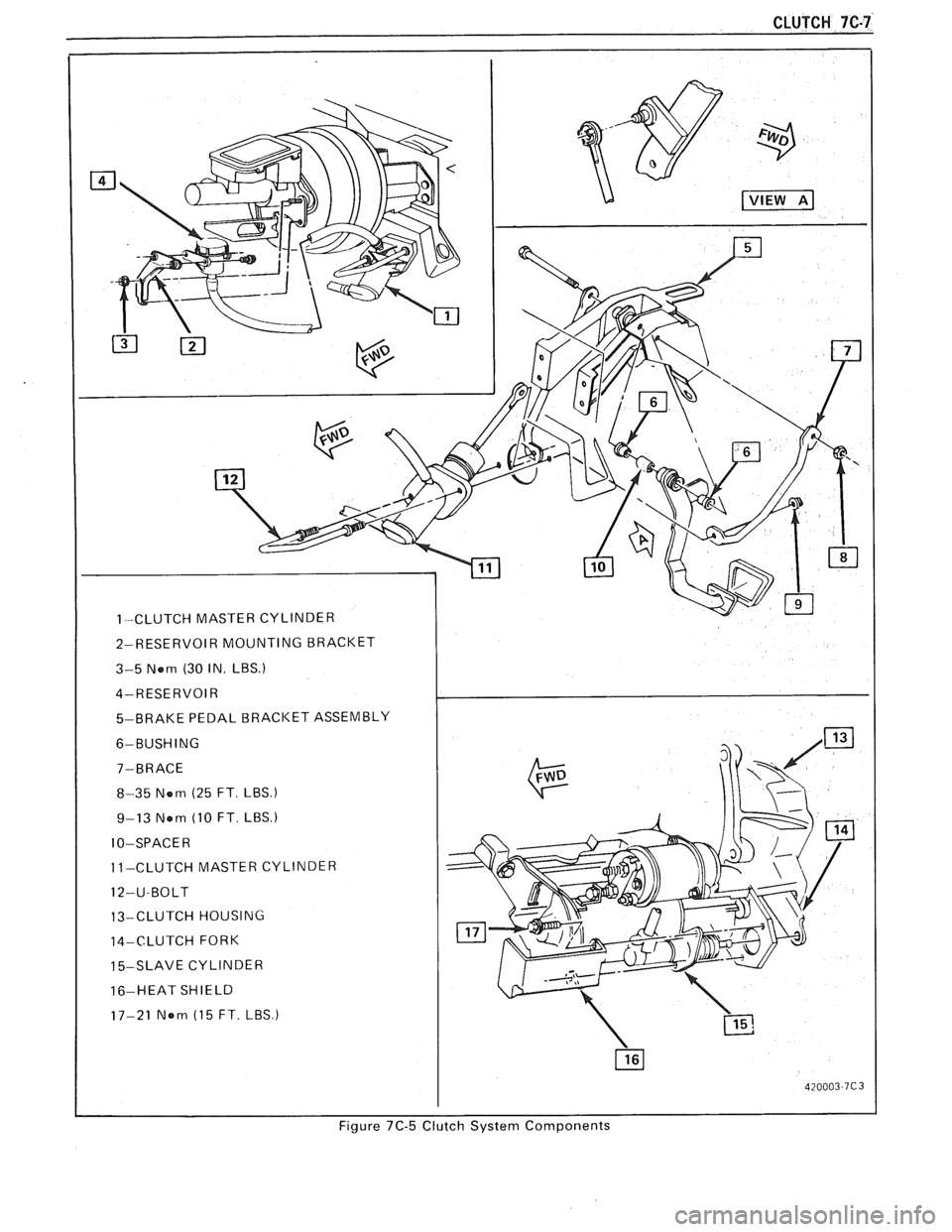
CLUTCH 7C-7
1-CLUTCH MASTER CYLINDER
2-RESERVOIR MOUNTING BRACKET
3-5 Nem (30 IN.
LBS.)
4-RESERVOIR
5-BRAKE PEDAL
BRACKET ASSEMBLY
6-BUSHING
8-35 Nem (25 FT
LBS.)
9-13 Nem (10 FT LBS.)
10-SPACE R
11-CLUTCH MASTER CYLINDER
12-U-BOLT
13-CLUTCH HOUSING
14-CLUTCH FORK
15-SLAVE CYLINDER
16-HEAT SHIELD
17-21
Nom (15 FT. LBS
Figure 7C-5 Clutch System Components