1988 PONTIAC FIERO brake
[x] Cancel search: brakePage 418 of 1825
ENGINE COOLING BB-7
NOTICE: If recommended quality antifreeze is
used, supplemental inhibitors or additives claiming
to provide increased cooling capability are not
necessary. They may be detrimental to the efficient
operation of the system, and represent an
unnecessary operating expense.
Every 12 months or 15,000 miles, the cooling
system should be serviced as follows;
1. Wash radiator cap and filler neck with clean
water.
2. Check coolant for proper level and freeze
protection.
3. Pressure test system and radiator cap for proper
pressure holding capacity, 103
kPa (15 psi). If
replacement of cap is required, use the proper cap
specified for car model.
4. Tighten hose clamps and inspect all hoses. Replace
hoses whenever cracked, swollen or otherwise
deteriorated.
5. Clean frontal area of radiator core and air
conditioning condenser.
DRAINING AND REFILLING THE COOLING
SYSTEM
Replace hoses every 24 months or 30,000 miles or
earlier if cracked, swollen or otherwise deteriorated.
Every two years or 30,000 miles, whichever first
occurs, the cooling system should be flushed and
refilled using the following recommended procedure:
1. Remove radiator cap, or thermostat housing cap
(VIN
0, J, R and U), when engine is cool by:
a. Slowly
rotating cap counterclockwise to
detent. (Do not press down while rotating.)
b. Wait until any
residual pressure (indicated
by a hissing sound) is relieved.
c. After all hissing ceases, press down on cap
while continuing to rotate
counterclockwise.
CAUTION: To avoid the danger of
being burned, do not remove radiator
cap while engine and radiator are still
hot. Scalding fluid and steam may be
blown out under pressure.
2. Remove the thermostat by using the wire handle
to lift it out of the housing (VIN
0, J, R and U).
3. With the thermostat removed, reinstall the
thermostat housing cap (VIN
0, J, R and U).
4. Open radiator drain valve and block drain plugs
to drain coolant. On VIN R and
9 (P series)
engines, open coolant pipe plugs.
5. Close valve. Reinstall drain plugs, and add
sufficient water to fill system.
6. Run engine, drain and refill the system, as
described in steps
4 and 5 a sufficient number of
times, until the drained liquid is nearly colorless.
Important
BLOCK DRIVE WHEELS, place
transmission in PARK (automatic
transmission) or NEUTRAL (manual
transmission) and set the parking brake. 7.
Allow system to drain completely. Then close
radiator drain valve tightly, and reinstall block
drain plugs.
8. Remove recovery cap leaving hoses in place.
Remove coolant recovery tank and empty of
fluid. Flush tank with clean water, drain and
reinstall.
9. Add sufficient ethylene glycol coolant, meeting
GM specification 1825-M, to provide the
required freezing and corrosion protection
- at
least 50 percent solution -37°C (-34°F). Fill
radiator to the base of the radiator fill neck and
add sufficient coolant to the recovery tank to
raise level to the "FULL" mark. Reinstall
recovery tank cap.
10. Run engine, with radiator cap or thermostat
housing cap removed, until normal operating
temperature is reached. (Radiator upper hose
becomes hot.)
11. With engine idling, add coolant until level
reaches bottom of filler neck and reinstall cap,
making certain arrows line up with overflow tube.
CAUTION: Under some conditions, the
ethylene glycol in engine coolant is
flammable. To help avoid being
burned when adding coolant, DO NOT
spill
it on the exhaust system or hat
engine parts.
It is the owner's responsibility to keep the freeze
protection at a level appropriate to the
temperatures which may occur in the area of
vehicle operation.
a. Maintain
cooling system freeze protection
at
-37°C (-34"F), to ensure protection
against corrosion and loss of coolant from
boiling, even though freezing temperatures
are not expected.
b. Add ethylene glycol base coolant that meets
GM Specification 1825-M, when coolant
additions are required because of coolant
loss, or to provide additional protection
against
freezing at temperatures lower than
-37°C (-34°F).
NOTICE: Alcohol or methanol base coolants, or
plain water, are not recommended at any time.
DRlVE BELT
NOTICE: Routine inspection of the belt may
reveal cracks in the belt ribs. These cracks will
not impair belt performance and therefore should
not be considered a problem requiring belt
replacement. However, the belt should be
replaced if belt slip occurs or if sections of the
belt ribs are missing.
A single (serpentine) belt is used to drive all
engine accessories formerly driven by multiple drive
belts. All belt driven accessories are ridgedly mounted
with belt tension maintained by a spring loaded
tensioner.
The drive belt tensioner has the ability to control
belt tension over a fairly broad range of belt lengths.
Page 447 of 1825
6D1-4 BATTERY
VOLTAGE
A. 16.0 or more
B. 14.0
- 15.9
C. 13.9 or less HOURS
1. Set parking brake and place automatic
Up to 4 Hours transmission in "PARK" (NEUTRAL for
Up to 8 Hours manual transmission.) Turn off the ignition,
Up to 16 Hours turn off lights, and all other electrical
If the charge current is still not
measurable
at the end of the above charging
times, the battery should be replaced.
If the charge current is measurable during
the charging time, the battery is considered to be
good and charging should be completed in the
normal manner.
5. It
is important to remember that a completely
discharged battery must be recharged for a
sufficient number of ampere hours (AH) to
restore it to a usable state. As a general rule of
thumb, using the reserve capacity rating (RC) of
the battery as the number of ampere hours of
charge will usually bring the green dot into view.
For example, if battery is rated at 75 RC minutes,
it would be completely recharged as follows:
10 ampere charge x 7-1/2 hours
= 75 AH
25 ampere charge x 3 hours = 75 AH, etc.
6. It
is recommended that any battery recharged by
this procedure be
LOAD TESTED to establish
serviceability.
JUMP STARTING IN CASE OF EMERGENCY
WITH AUXILIARY (BOOSTER) BAVEEWY
NOTICE: Do not push or tow the vehicle to start.
Damage to the emission system, or to other parts
of the vehicle may result.
Both booster and discharged battery should be
treated carefully when using jumper cables. Follow the
procedure outlined below, being careful not to cause
sparks:
CAUTION: Departure from these
conditions or the procedure below
could result in:
(1) Serious personal
injury (particularly to eyes) or property
damage from such causes as battery
explosion, battery acid, or electrical
burns; and/or
(2) damage to electronic
components of either vehicle.
Never expose battery to open flame or electric
spark
- batteries generate a gas which is flammable and
explosive.
Remove rings, watches, and other jewelry. Wear
approved eye protection.
Do not allow battery fluid to contact eyes, skin,
fabrics, or painted surfaces
- fluid is a corrosive acid.
Flush any contacted area with water immediately and
thoroughly. Be careful that metal tools or jumper
cables do not contact the positive battery terminal (or
metal in contact with it) and any other metal on the
car, because a short circuit could occur. Batteries
should always be kept out of the reach of children.
loads.
2. Check the built-in hydrometer. If it is clear or
light yellow, replace the battery.
3. Attach the end of one jumper cable to the positive
terminal of the booster battery and the other end
of the same cable to the positive terminal of the
discharged battery. Do not permit vehicles to
touch each other as this could cause a ground
connection and counteract the benefits of this
procedure. (Use 12-volt battery only to jump start
the engine).
4. Attach one end of the remaining negative cable
to the negative terminal of the booster battery,
and the other end to a solid engine ground (such
as
A/C compresser bracket or generator
mounting bracket) at least 18 inches from the
battery of the vehicle being started (DO NOT
CONNECT DIRECTLY TO THE NEGATIVE
TERMINAL OF THE DEAD BATTERY).
5. Start the engine of the vehicle that is providing
the jump start and turn off electrical accessories.
Then start the engine in the car with the
discharged battery.
6. Reverse these directions exactly when removing
the jumper cables. The negative cable must be
disconnected from the engine that was jump
started first.
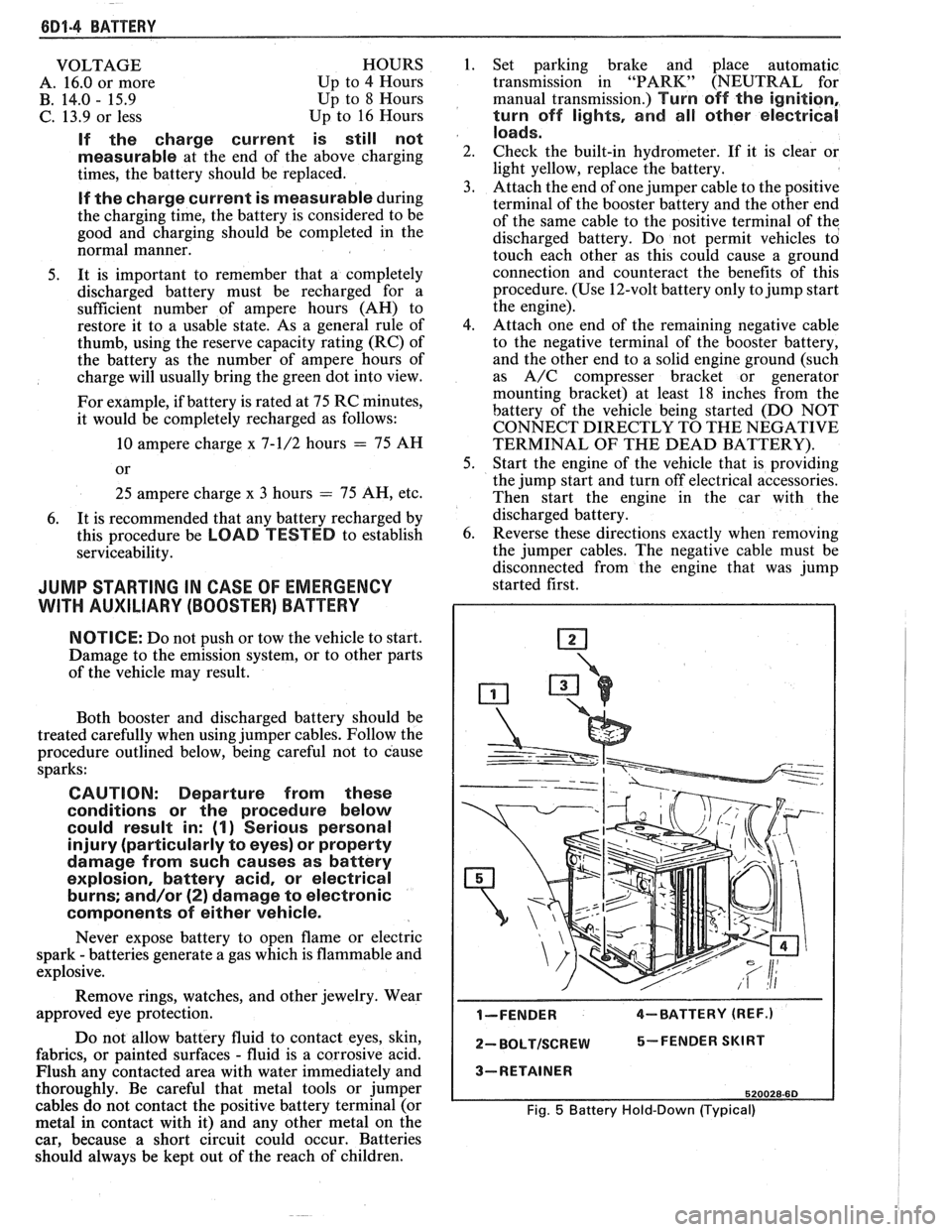
I-FENDER 4-BATTERY (REF.)
2- BOLTISCREW 5-FENDER SKIRT
3-RETAINER
520028-60
Fig. 5 Battery Hold-Down (Typical)
Page 455 of 1825
(iD2.4 CRANKING SYSTEM
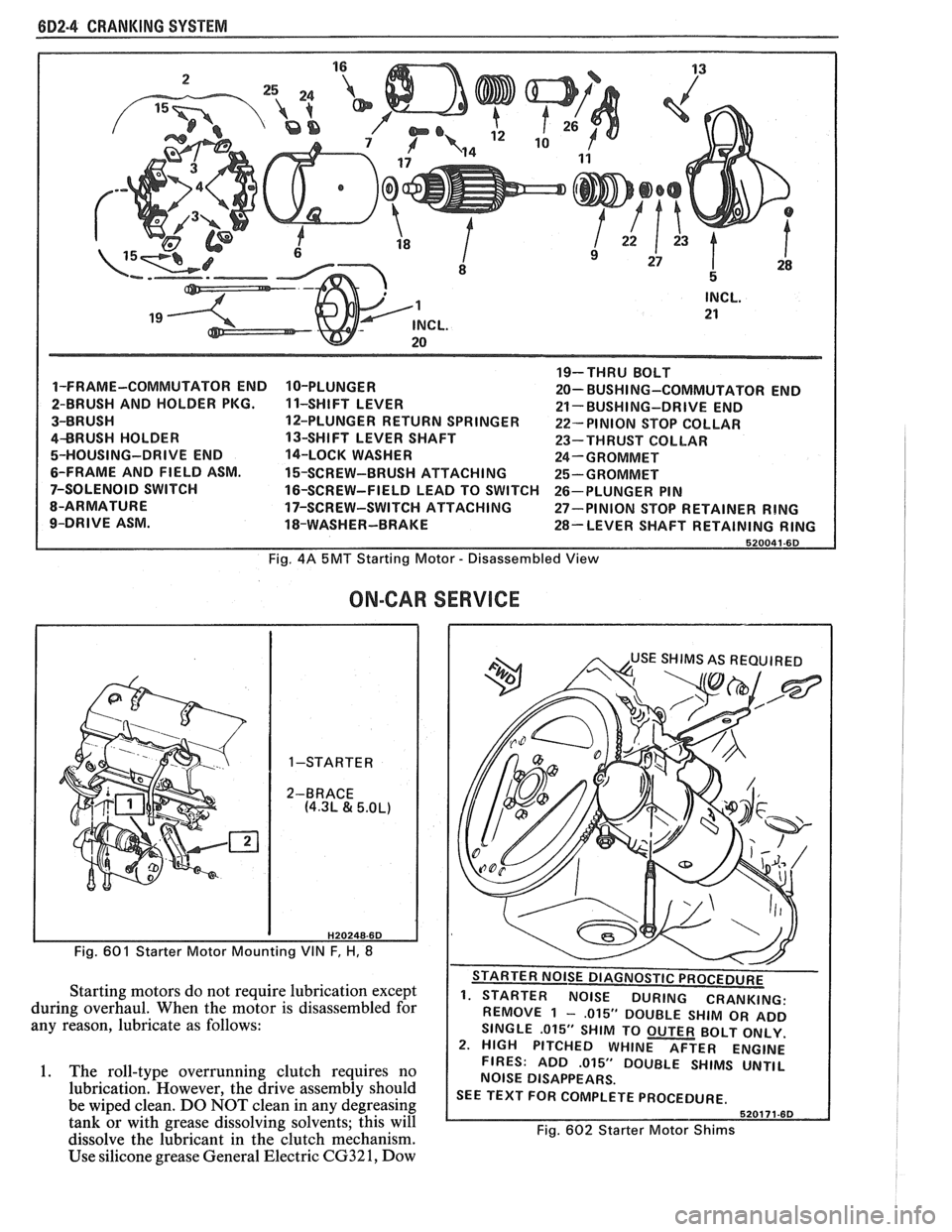
1-FRAME-COMMUTATOR END
2-BRUSH AND HOLDER PKG.
3-BRUSH
4BRUSH HOLDER
5-HOUSING-DRIVE END
6-FRAME AND FIELD ASM.
7-SOLENOID SWITCH
8-ARMATURE
9-DRIVE ASM. 10-PLUNGER
1 1-SHIFT
LEVER
12-PLUNGER RETURN SPRINGER
13-SHIFT LEVER SHAFT
14-LOCK WASHER
15-SCREW-BRUSH ATTACHING
16-SCREW-FIELD LEAD TO SWITCH
17-SCREW-SWITCH ATTACHING
18-WASHER-BRAKE 19-THRU
BOLT
20- BUSHI NG-COMMUTATOR END
21- BUSHING-DRIVE END
22- PINION STOP COLLAR
23-THRUST COLLAR
24-GROMMET
25-GROMMET
26-PLUNGER PIN
27-PINION STOP RETAINER
RING
28-LEVER SHAFT RETAINING RING
Fig. 4A 5MT Starting Motor - Disassembled View
ON-CAR
H20248-6D
Fig. 601 Starter Motor Mounting VIN F, H, 8
Starting motors do not require lubrication except
during overhaul. When the motor is disassembled for
any reason, lubricate as follows:
1. The roll-type overrunning clutch requires no
lubrication. However, the drive assembly should
be wiped clean. DO NOT clean in any degreasing
tank or with grease dissolving solvents; this will
dissolve the lubricant in the clutch mechanism.
Use silicone grease General Electric
CG32 1, Dow
SERVICE
. - . . . - - . REMOVE 1 - ,015" DOUBLE SHIM OR ADD
SINGLE
.015" SHIM TO OUTER BOLT ONLY.
2. HIGH PITCHED WHINE AFTER ENGINE
FIRES: ADD
.015" DOUBLE SHIMS UNTIL
NOISE DISAPPEARS.
SEE TEXT FOR COMPLETE PROCEDURE.
Fig. 602 Starter Motor Shims
Page 552 of 1825
DRIVEABILITY AND EMISSIONS 5.OL (VIN E) 6E2-B-5
@ If the previous checks did not find the problem:
- Visually inspect ignition system for moisture,
dust, cracks, burns, etc. Spray plug wires with
fine water mist to check for shorts.
- Fuel System - Plugged fuel filter, water, low
pressure. See CHART A-7.
- Perform compression check.
- Valve timing.
- Remove rocker covers. Check for bent pushrods,
worn rocker arms, broken or weak valve springs,
worn camshaft lobes. Repair as necessary. See
Section
"6A".
If there is spray from only one injector, then,
there is
a malfunction in the injector assembly,
or in the signal to the injector assembly. The
malfunction can be isolated by switching the
injector connectors. If the problem remains with
the original injector, after switching the
connector, then the injector is defective. Replace
the iniector. If the
~roblem moves with the
injector connector, then, the problem is an
improper signal in the injector circuits. See
CHART A-3.
POOR FUEL ECONOMY
Definition: Fuel economy, as measured by an actual road test, is
noticeably lower than expected. Also, economy is noticeably lower than it
was on this car at one time, as previously shown by an actual road test.
@ CHECK: @ Visually (physically) check:
- Engine thermostat for faulty part (always open) - Vacuum hoses for splits, kinks, and proper
or for wrong heat range. See Section
"6B". connections, as shown on Vehicle Emission
- Fuel Pressure. See CHART A-7. Control Information label.
@ Check owner's driving habits. - Ignition wires for cracking, hardness, and proper
- Is A/C "ON" full time (Defroster mode "ON")? connections.
- Are tires at correct pressure? e Check ignition timing. See Emission Control
- Are excessively heavy loads being carried? Information label.
- Is acceleration too much, too often? @ Remove spark plugs. Check for cracks, wear,
- Suggest driver read "Important Facts on Fuel
improper gap, burned electrodes or heavy deposits.
Economy" in owner's manual. Repair
or replace, as necessary.
@ Perform "Diagnostic Circuit Check". @ Check compression. See Section "6A".
@ Check air cleaner element (filter) for dirt or @ Check TCC for proper operation. See CHART C-8.
being plugged. Use "Scan"
tool if available.
@ Check for proper calibration of speedometer. @ Check for dragging brakes.
Suggest owner fill fuel tank and recheck fuel
economy.
@ Check for exhaust system restriction. ,
See CHART B-1.
ROUGH, UNSTABLE, OR INCORRECT IDLE, STALLING
Definition: The engine runs unevenly at idle. If bad enough, the car may
shake. Also,
the idle may vary in rpm (called "hunting"). Either condition
may be severe enough to cause stalling. Engine idles at incorrect speed.
@ CHECK: - Vacuum leaks can cause higher than normal
- Ignition timing. See Emission Control idle.
Information label.
- EGR "ONJ', while idling, will cause roughness,
- PIN switch circuit. See CHART C-1 A. stalling, and hard starting. CHART C-7.
- For injectorb) leaking. Check fuel pressure, - Battery cables and ground straps should be clean ,
CHART A-7. and secure. Erratic voltage will cause IAC to
- IAC - See CHART C-2C.
change its position, resulting in poor idle quality.
- If a sticking throttle shaft or binding linkage - IAC valve will not move, if system voltage is
causes
a high TPS voltage (open throttle
below 9, or greater than 17.8 volts.
indication), the ECM will not control idle.
- Use "Scan" tool to determine if ECM is receiving
Monitor TPS voltage. "Scan"
andlor voltmeter AlC request signal.
should read less than
1.2 volts with throttle
closed.
Page 626 of 1825
DRIVEABILITY AND EMISSIONS - 5.0L (VIM E) 6E2-C8-1
SECTION C8
"FRANSMISSIBN CONVERnEW CLUTCH (TCC) SYSTEM
CONTENTS
GENERAL DESCRIPTION ............... C8-1 RESULTS OF INCORRECT TCC
PURPOSE
........................ C8-1 OPERATION ..................... C8-2
......................... OPERATION ...................... C8-1 DIAGNOSIS CS-2
.................... CIRCUIT DESCRIPTION ....e.e..eea..e C8-1 ON-CAR SERVICE C8-2
................. PARTS INFORMATION C8-2
GENERAL DESCRIPTION
PURPOSE
The transmission converter clutch (TCC) system
is designed to eliminate power loss by the converter
(slippage) thus increasing fuel economy. By locking
the converter clutch,
a more effective coupling to the
flywheel is achieved. The converter clutch is operated
by an ECM controlled solenoid.
OPERATION
Engagement of the TCC is accomplished by a
solenoid operated valve within the transmission. The
solenoid is activated when an internal switch in the
ECM is grounded. Although the ECM may command
the TCC
"ON", the converter clutch will not apply
until internal transmission fluid pressure require-
ments are met. See Section
"7A".
Before the ECM activates the TCC apply solenoid,
several inputs must be monitored:
e Vehicle Speed. Must be above a certain value
before the TCC can be applied.
Coolant Temperature. The engine coolant
temperature must be above a certain value
before the TCC can be applied.
@ Throttle Position Sensor. After the TCC is
applied, during low engine load condition, the
ECM uses the information from the TPS to
release the clutch when the car is accelerating
or decelerating at a certain rate.
CIRCUIT DESCRIPTION
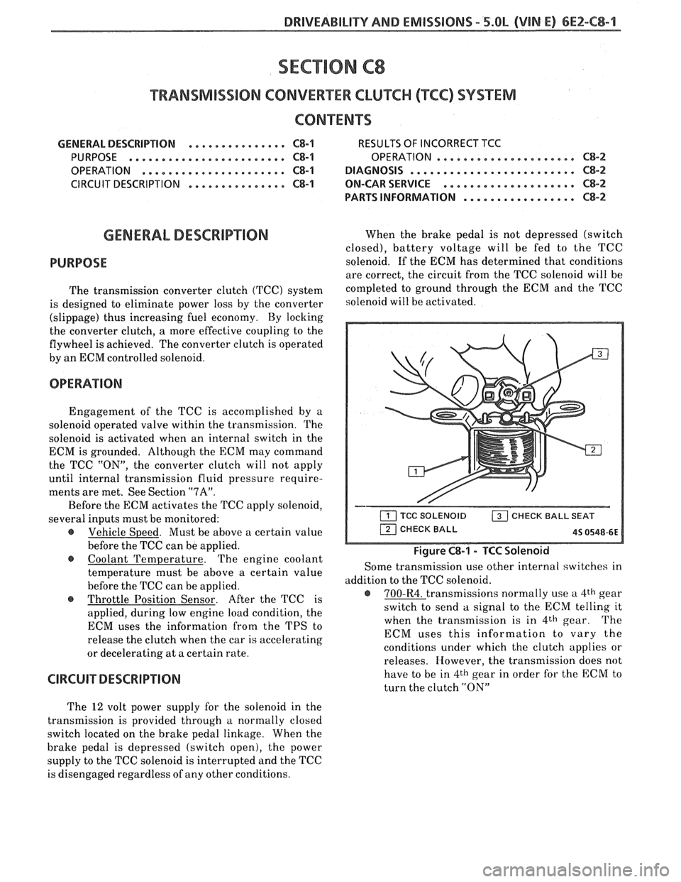
When the brake pedal is not depressed (switch
closed), battery voltage will be fed to the TCC
solenoid. If the ECM has determined that conditions
are correct, the circuit from the TCC solenoid will be
completed to ground through the ECM and the TCC
solenoid will be activated.
Figure C8-1 - TCC Solenoid
Some transmission use other internal switches in
addition to the TCC solenoid.
@ 700-R4. transmissions normally use a 4th gear
switch to send
a signal to the ECM telling it
when the transmission is in
4th gear. The
ECM uses this information to vary the
conditions under which the clutch applies or
releases. However, the transmission does not
have to be in
4th gear in order for the ECM to
turn the clutch
"ON"
The 12 volt power supply for the solenoid in the
transmission is provided through
a normally closed
switch located on the brake pedal linkage. When the
brake pedal is depressed (switch open), the power
supply to the TCC solenoid is interrupted and the TCC
is disengaged regardless of any other conditions.
Page 627 of 1825
6Ef-C8-2 BRlVEABlLlYV AND EMISSIONS - 5.OL (VIN E) ----
RESULTS OF INCORRECTTCC OPERATION
An engine stall will result if the converter clutch
remains applied at all times.
If the converter clutch does not apply, fuel
economy may be lower than expected.
The transmission converter clutch
(TCC) system
has different operating characteristics than an
automatic transmission without TCC.
If the driver
complains of a "chuggle" or "surge" condition, the car
should be road tested and compared to a similar car to
see if a real problem exists. Another TCC complaint
may be
a downshift felt when going up a grade,
especially with cruise control. This may not be
a
downshift, but a clutch disengagement due to the
change in TPS to maintain cruising speed. The
Owner's Manual section on TCC operation should be
reviewed with the driver.
DIAGNOSIS
The diagnosis of the TCC system is covered in
ClIART C-8. If the ECM detects a problem in the VSS
system, a Code
24 should set. In this case see Code 24
Chart.
If the ECM doesn't switch the TCC "ON" when
driving, but will turn it
"ON" when the "test"
terminal is grounded with ignition "ON" and engine
stopped, the sensors such as coolant, speed, and
throttle position should be checked.
ON-CAW SERVICE
@ See Section "7" for TCC Solenoid.
@ See Section "SH" for VSS (HP mounted) and brake
system.
PAR- SNFORMATBIQN
PART NAME GRQUQ
.......................... Sensor, VSS 9.761
........................ Solenoid, TCC 4.122
Page 629 of 1825

6EZ-C8-4 DRIVEABILITY AND EMISSIONS - 5.OL (VIN E)
I5 WAY (FRONT VIEW)
SPEED INPUT
4rH GEAR SIGNAL
422 TANIBLK
ALDL CONNECTOR
CHART C-8A
TRANSMISSION CONVERTER CLUTCH (TCC)
ELECTRICAL DIAGNOSIS
(Page 1 of 2)
5.OL (VIN E) "F" "SERIES (TBI)
Circuit Description:
The purpose of the automatic transmission torque converter clutch is to eliminate the power loss of the
torque converter, when the vehicle is in a cruise condition. This allows the convenience of the automatic
transmission and the fuel economy of a manual transmission.
Fused battery ignition is supplied to the TCC solenoid through the brake switch. the ECM will engage
TCC
by grounding CKT 422 to energize the solenoid.
TCC will engage when:
- Vehicle speed above 24 mph - Engine at normal operating temperature (above 70°C, 156°F)
- Throttle position sensor output not changing, indicating a steady road speed
- Brake switch closed
Test Description: Numbers below refer to circled solenoids
and relays before installing a
numbers on the diagnostic chart. replacement ECM. Replace
any solenoid or relay
1. Confirms 12 volt supply as well as continuity of that
measures less than 20 ohms.
TCC circuit.
2. Grounding the diagnostic terminal with engine Diagnostic Aids:
"OFF", should energize the capability of the ECM An
engine coolant thermostat that is stuck open or
to control the solenoid. opens
at too low a temperature, may result in an
3. Solenoid coil resistance must measure more than inoperative TCC.
20 ohms. Less resistance will cause early failure
of the ECM
drive^.". Using an ohmmeter, check
the solenoid coil resistance of
all ECM controlled
Page 658 of 1825
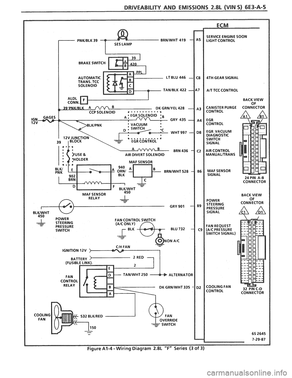
DRIVEABILITY AND EMISSIONS 2.8L (VIN S) 6E3-A-5
ECM
BRAKE SWITC
BACK
VIEW OF
AIR DIVERT SOLENOID
MANUALITRANS
IGNITION 12V
TANMIHT 250 ALTERNATOR
Figure A1-4 - Wiring Diagram 2.8L "F" Series (3 of 3)