1988 PONTIAC FIERO brake
[x] Cancel search: brakePage 1166 of 1825
CONTENTS
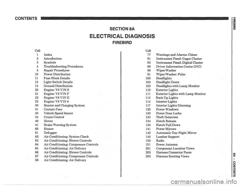
ELECTRICAL DIAGNOSIS
Cell
1
2
3
4 5
10
11
12 14
20
21
22
23
30
31
33
34
40
4
1
60
61
62
63
64
65
66
67
68
Index
Introduction
Symbols
Troubleshooting Procedures Repair Procedures
Power Distribution
Fuse Block Details
Light Switch Details
Ground Distribution
Engine:
V6 VIN S
Engine: V8 VIN
F
Engine: V8 VIN E
Engine:
V8 VIN 8
Starter and Charging System
Coolant Fans
Vehicle Speed Sensor
Cruise Control Horns
Brake Warning System
Heater
Defogger
Air Conditioning: System Check
Air Conditioning: Blower Controls
Air Conditioning: Compressor Controls
Air Conditioning: Air Delivery
Air Conditioning: Blower Controls
Air Conditioning: Compressor Controls
Air Conditioning: Air Delivery Cell
77
8
1
82
86 90
9
1
100
102
103
110
111
112
114
117
120
130
133
134
135
141
143
145
150
151
201 202
203
Warnings and Alarms: Chime
Instrument Panel: Gages Cluster
Instrument Panel:
Digital Cluster
Driver Information Center
(DIC)
WiperlWasher
WiperlWasher: Pulse
Headlights
Headlight Doors
Headlights with Lamp Monitor
Exterior Lights
Exterior Lights with Lamp Monitor
Back Up Lights
Interior Lights
Interior Lights Dimming
Power Windows
Power Door Locks
Theft Deterrent
Hatch Release
Hatch Pull-Down
Power Mirrors
Automatic Day-Night Mirror
Lumbar Support
Radio Power Antenna
Component Location Views
Harness Connector Faces
Harness Routing Views
Page 1167 of 1825
Page
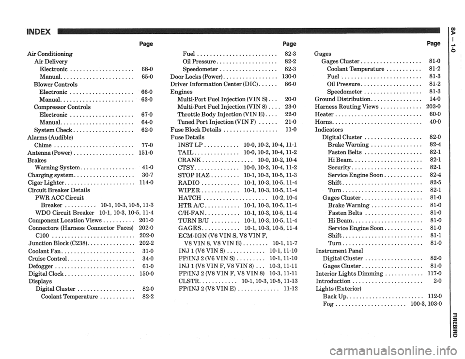
Air Conditioning
Air Delivery
Electronic
.................... 68-0
Manual
....................... 65-0
Blower Controls
Electronic
.................... 66-0
Manual
....................... 63-0
Compressor Controls Electronic
.................... 67-0
Manual
....................... 64-0
................... System Check 62-0
Alarms (Audible)
Chime
......................... 77-0
Antenna(Power) ................... 151-0
Brakes
................. Warning System 41-0
................... Charging system 30-7
...................... Cigar Lighter 114-0
Circuit Breaker Details
PWR ACC Circuit
.......... Breaker 10.1.10.3.10.5.1 1.3
WDO Circuit Breaker
10.1. 10.3. 10.5. 11-4
.......... Component Location Views 201-0
Connectors (Harness Connector Faces) 202-0
el00 .......................... 202-0
............... Junction Block ((2238) 202-2
Coolant Fan
....................... 31-0
Cruise Control
..................... 34-0
Defogger
......................... 61-0
Digital Clock
...................... 150-0
Displays Digital Cluster
.................. 82-0
Coolant Temperature
........... 82-2
Page
......................... Fuel 82-3
................... Oil Pressure 82-2
.................. Speedometer 82-3
................. Door Locks (Power) 130-0
...... Driver Information Center (DIC) 86-0
Engines
... Multi-Port Fuel Injection (VIN S) 20-0
.... Multi-Port Fuel Injection (VIN 8) 23-0
.... Throttle
Body Injection (VIN E) 22-0
...... Tuned
Port Injection (VIN F) 21-0
................. Fuse Block Details 11-0
Fuse Details
........... INST LP 10.0.10.2.10.4.1 1.1
.............. TAIL 10.0.10.2.10.4.1 1.2
................ CRANK 10.0.10.2.1 0.4
.............. CTSY 10~0.10.2.10.4.1 1.2
......... STOP HAZ 10.1.10.3.10.5.1 1.3
............ RADIO 10.1.10.3.10.5.1 1.4
............ WIPER 10.1.10.3.10.5.1 1.4
.................... HATCH 10.2.1 0.4
........... HTR AlC 10.1.10.3.10.5.1 1.4
........... CIH.FAN 10.1.10.3.10.5.1 1.4
......... TURN BIU 10.1.10.3.10.5.1 1.4
............ GAGES 10.1.10.3.10.5.1 1.4
ECM-IGN
(V6 VIN S. V8 VIN F.
........ V8 VIN 8. V8 VIN E) 10.1.1 1.7
............ INJ 1 (V6 VIN S) 10.1.1 1.10
......... FPIINJ 2 (V6 VIN S) 10.1.1 1.10
... INJ 1 (V8 VIN F. V8 VIN 8) 10.3.1 1.11
FPIINJ 2 (V8 VIN F. V8 VIN 8) 10.3.1 1.11
............ CLSTR 10.1.10.3.10.5.1 1.13
............. FPIINJ 2 (V8 VIN E) 11-12
Page
Gages
................... Gages Cluster 81-0
........... Coolant Temperature 81-2
......................... Fuel 81-3
................... Oil Pressure 81-2
.................. Speedometer 81-3
................ Ground Distribution 14-0
Harness Routing Views
............. 203-0
........................... Heater 60-0
............................ Horns 40-0
Indicators
.................. Digital Cluster 82-0
................ Brake Warning 82-4
.................. Fasten Belts 82-1
...................... Hi Beam 82-1
...................... Security 82-1
............ Service Engine Soon 82-4
......................... Shift 82-5
......................... Turn 82-1
................... Gages Cluster 81-0
................ Brake Warning 81-0
.................. Fasten Belts 81-0
...................... Hi Beam 81-0
............ Service Engine Soon 81-0
......................... Shift 81-1
......................... Turn 81-0
Instrument Panel
Digital Cluster
.................. 82-0
Gages Cluster
................... 81-0
............ Interior Lights Dimming 117-0
...................... Introduction 2-0
Lights (Exterior)
........................ Back Up 112-0
...................... Fog 100.3,10 3.0
Page 1212 of 1825
POWER DISTRIBUTION
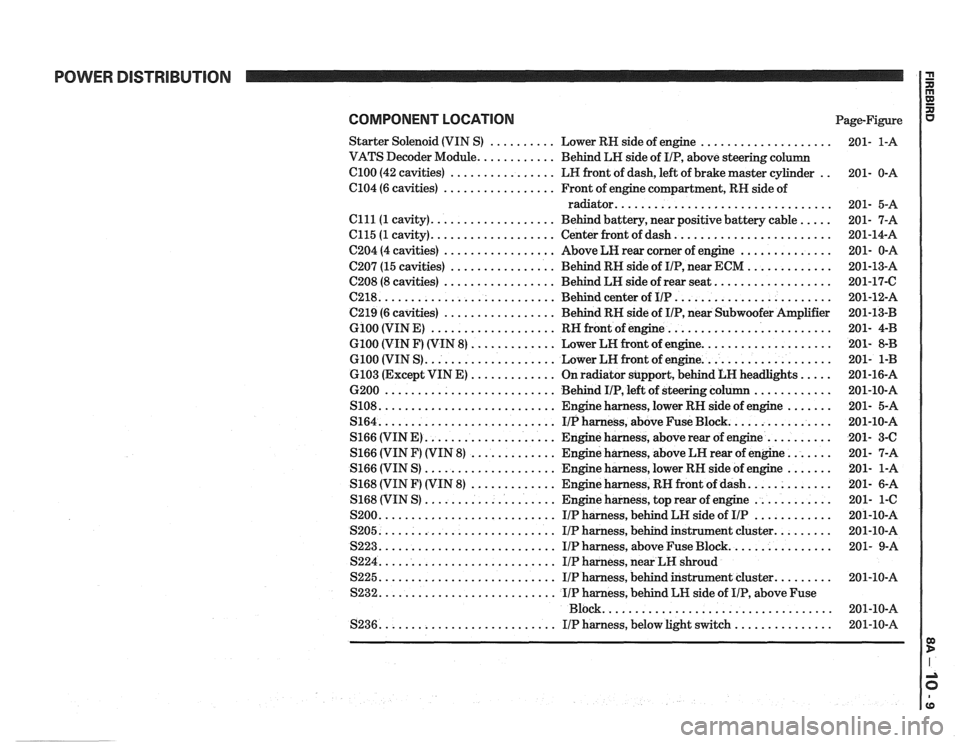
COMPONENT LOCATION Page-Figure
Starter Solenoid (VIN
S) .......... Lower RH side of engine ....................
VATS Decoder Module ............ Behind LH side of IIP. above steering column
el00 (42 cavities) ................ LH front of dash. left of brake master cylinder ..
C104 (6 cavities) ................. Front of engine compartment. RH side of
radiator
.................................
Clll(1 cavity) ................... Behind battery. near positive battery cable .....
C115 (1 cavity) ................... Center front of dash ........................
C204 (4 cavities) ................. Above LH rear corner of engine ..............
C207 (15 cavities) ................ Behind RH side of IIP. near ECM .............
C208 (8 cavities) ................. Behind LH side of rear seat ..................
(2218 ........................... Behind center of IIP ........................
C219 (6 cavities) ................. Behind RH side of IIP. near Subwoofer Amplifier
G100 (VIN E) ................... RH front of engine .........................
G100 (VIN F) (VIN 8) ............. Lower LH front of engine ....................
G100 (VIN S) .................... Lower LH front of engine ....................
6103 (Except VIN E) ............. On radiator support. behind LH headlights .....
6200 .......................... Behind IIP. left of steering column ............
S108 ........................... Engine harness. lower RH side of engine .......
S164 ........................... IIPharness. aboveFuseBlock ................
S166 (VIN E) .................... Engine harness. above rear of engine ..........
S166 (VIN F) (VIN 8) ............. Engine harness. above LH rear of engine .......
S166 (VIN S) .................... Engine harness. lower RH side of engine .......
S168 (VIN F) (VIN 8) ............. Engine harness. RH front of dash .............
S168 (VIN S) .................... Engine harness. top rear of engine ............
S200 ........................... IIP harness. behind LH side of IIP ............
S205 ........................... IIP harness. behind instrument cluster .........
S223 ........................... IIP harness. above Fuse Block ................
S224 ........................... IIP harness. near LH shroud
S225
........................... IIP harness. behind instrument cluster .........
S232 ........................... IIP harness. behind LH side of IIP. above Fuse
................................... Block
S236
........................... IIP harness. below light switch ...............
Page 1250 of 1825
MULTI-PORT FUEL INJECTION: V6 VIN S
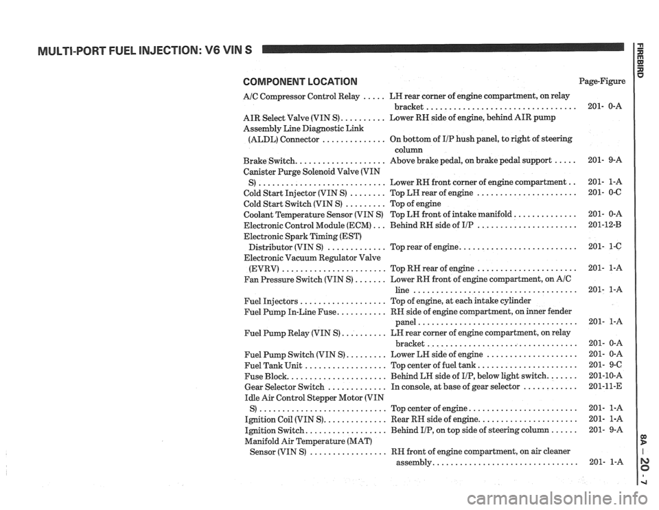
COMPONENT LOCATION
AIC Compressor Control Relay ..... LH rear corner of engine compartment, on relay
................................. bracket
AIR Select Valve (VIN S)
.......... Lower RN side of engine, behind AIR pump
Assembly Line Diagnostic Link
(ALDL) Connector
.............. On bottom of IIP hush panel, to right of steering
column
Brake Switch.
................... Above brake pedal, on brake pedal support .....
Canister Purge Solenoid Valve (VIN
............................ .. S) Lower RH front
corner of engine compartment
Cold Start Injector (VIN S)
........ Top LH rear of engine ......................
Cold Start Switch (VIN S) ......... Top of engine
Coolant Temperature Sensor (VIN S) Top LN front of intake manifold.
.............
Electronic Control Module (ECM) ... Behind RH side of IIP ......................
Electronic Spark Timing (EST)
......................... Distributor (VIN S) ............. Top rear of engine.
Electronic Vacuum Regulator Valve
(EVRV)
....................... TopRHrearofengine ......................
Fan Pressure Switch (VIN S) ....... Lower RH front of engine compartment, on AIC
line ....................................
Fuel Injectors ................... Top of engine, at each intake cylinder
Fuel Pump In-Line Fuse.
.......... RH side of engine compartment, on inner fender
panel
...................................
Fuel Pump Relay (VIN S) .......... LH rear corner of engine compartment, on relay
................................. bracket
Fuel Pump Switch (VIN S)
......... Lower LH side of engine ....................
Fuel Tank Unit .................. Top center of fuel tank ......................
Fuse Block. ..................... Behind LH side of IIP, below light switch. ......
Gear Selector Switch ............. In console, at base of gear selector ............
Idle Air Control Stepper Motor (VIN
S)
............................ Topcenterofengine ........................
Ignition Coil (VIN S). ............. Rear RH side of engine. .....................
Ignition Switch. ................. Behind IIP, on top side of steering column ......
Manifold Air Temperature (MAT)
................. Sensor (VIN S) RH front of engine compartment, on air cleaner
............................... assembly. Page-Figure
Page 1251 of 1825
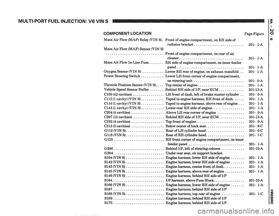
COMPONENT LOCATION Page-Figure
Mass Air Flow (MAF) Relay (VIN
S) . Front of engine compartment. on RH side of
radiator bracket
..........................
Mass Air Flow (MAF) Sensor (VIN S)
Front of engine compartment. on rear of
air ..............................
cleaner ..................................
Mass Air Flow In-Line Fuse ........ RH side of engine compartment. on inner fender
panel
...................................
Oxygen Sensor (VIN S) ........... Lower RH rear of engine. on exhaust manifold ..
Power Steering Switch ............ Lower LH front corner of engine compartment.
on steering unit
..........................
Throttle Position Sensor (VIN S) .... Top center of engine ........................
Vehicle Speed Sensor Buffer ....... Behind RW side of IIP. near ECM .............
.. ................ ClOO (42 cavities) LH front of dash. left of brake master cylinder
...... ............ C113 (1 cavity) (VIN S) Taped
to engine harness. RH front of dash
... ............ C114 (1 cavity) (VIN S) Taped to engine harness. above rear of engine
............ ................. C143 (1 cavity) (VIN S) Lower rear RH side of engine
.............. C204 (4 cavities) ................. Above LR rear corner of engine
............. C207 (15 cavities) ................ Behind RH side of IIP. near ECM
......................... C222 (4 cavities) ................. Top front of engine
.................... ................. C313 (3 cavities) Below center of back seat
.................... 6112 (VIN S) .................... Rear of LW cylinder head
.................... 6118 (VIN S) .................... Rear of RH cylinder head
6123
.......................... RH front corner of engine compartment. on inner
............................. fenderpanel
............ .......................... 6200 Behind IIP. left of steering column
6304
.......................... Under rear seat. on support bracket
....... .................... S104 (VIN S) Engine harness. lower RH side of engine
....... S142 (VIN S) .................... Engine harness. lower RH side of engine
........... S143 (VIN S) .................... Engine harness. center front of dash
.......... S145 (VIN S) .................... Engine harness. above rear of engine
.................... S146 (VIN S) Engine harness. behind RH side of IIP
S164 ........................... IIPharness. aboveFuseBlock ................
....... S166 (VIN S) .................... Engine harness. lower RH side of engine
S167
........................... Engine harness. behind RH side of IIP
............ S168 (VIN S) .................... Engine harness. top rear of engine
S169
........................... Engine harness. behind RN side of IIP
S170 ........................... Engine harness. behind RH side of IIP
Page 1264 of 1825
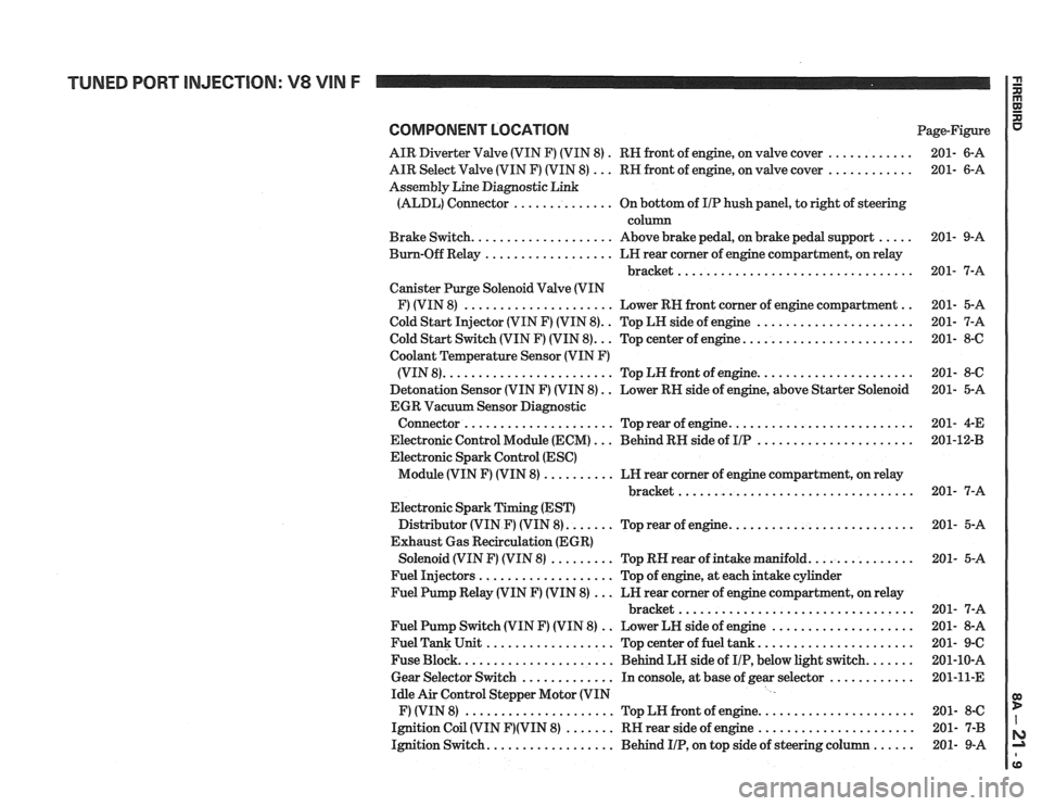
COMPONENT LOCATION Page-Figure
AIR Diverter Valve (VIN F) (VIN 8)
. RN front of engine, on valve cover ............ 201- 6-A
AIR Select Valve (VIN F) (VIN 8)
... RN front of engine, on valve cover ............ 201- 6-A
Assembly Line Diagnostic Link
(ALDL) Connector
.............. On bottom of IIP hush panel, to right of steering
column
Brake Switch.
................... Above brake pedal, on brake pedal support ..... 201- 9-A
Bum-Off Relay
.................. LN rear comer of engine compartment, on relay
bracket
................................. 201- 7-A
Canister Purge Solenoid Valve (VIN
F) (VIN 8)
..................... Lower RN front corner of engine compartment .. 201- 5-A
Cold Start Injector (VIN F) (VIN 8).
. Top LH side of engine ...................... 201- 7-A
.. ....................... Cold Start Switch (VIN F) (VIN 8). Top center of engine. 201- 8-6
Coolant
Temperature Sensor (VIN F)
..................... (VIN 8). ....................... Top LN front of engine. 201- 8-C
Detonation Sensor (VIN F) (VIN 8)
. . Lower RN side of engine, above Starter Solenoid 201- 5-A
EGR Vacuum Sensor Diagnostic
......................... Connector ..................... Top rear of engine. 201-
4-E
Electronic Control Module (ECM)
... Behind RN side of IIP ...................... 201-1243
Electronic Spark Control (ESC)
Module (VIN F) (VIN 8)
.......... LN rear corner of engine compartment, on relay
............................... bracket.. 201- 7-A
Electronic Spark Timing (EST)
Distributor (VIN
F) (VIN 8). ...... Top rear of engine. ......................... 201- 5-A
Exhaust Gas Recirculation (EGR)
Solenoid (VIN
F) (VIN 8) ......... Top RN rear of intake manifold. .............. 201- 5-A
Fuel Injectors
................... Top of engine, at each intake cylinder
Fuel Pump Relay (VIN
F) (VIN 8) ... LN rear corner of engine compartment, on relay
bracket
................................. 201- 7-A
Fuel Pump Switch (VIN
F) (VIN 8) .. Lower LN side of engine .................... 201- 8-A
Fuel Tank Unit
.................. Top center of fuel tank ...................... 201- 9-C
Fuse Block.
..................... Behind LH side of IIP, below light switch. ...... 201-10-A
Gear Selector Switch
............. In console, at base of gear selector ............ 201-11-E
Idle Air Control Stepper Motor (VIN
F) (VIN 8)
..................... Top LN front of engine. ..................... 201- 8-C
Ignition Coil (VIN
F)(VIN 8) ....... RN rear side of engine ...................... 201- 7-B
Ignition Switch.
................. Behind IIP, on top side of steering column ...... 201- 9-A
Page 1265 of 1825
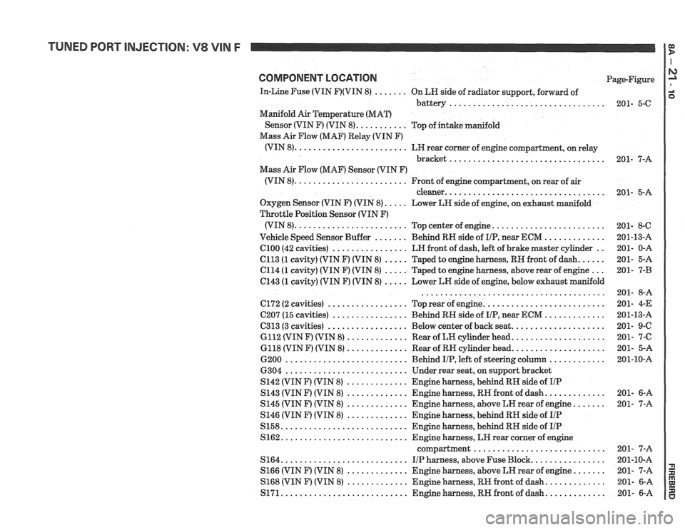
TUNED PORT INJECTION: V8 VIN F
COMPONENT LOCATION Page-Figure
In-Line Fuse (VIN
F)(VIN 8) ....... On LN side of radiator support, forward of
battery..
............................... 201- 5-C
Manifold
Air Temperature (MAT)
Sensor (VIN
F) (VIN 8). .......... Top of intake manifold
Mass Air Flow (MAF) Relay (VIN F)
(VIN 8). ....................... LN rear corner of engine compartment, on relay
bracket
................................. 201- 7-A
Mass Air Flow (MAF) Sensor (VIN F)
(VIN 8).
....................... Front of engine compartment, on rear of air
cleaner.
................................. 201- 5-A
Oxygen Sensor (VIN
F) (VIN 8). .... Lower LH side of engine, on exhaust manifold
Throttle Position Sensor (VIN F)
(VIN 8).
....................... Top center of engine. ....................... 201- 8-6
............. Vehicle Speed Sensor Buffer ....... Behind RH side of IIP, near ECM 201-13-A
C100 (42
cavities) ................ LN front of dash, left of brake master cylinder .. 201- 0-A
ell3 (1 cavity) (VIN F) (VIN 8) ..... Taped to engine harness, RH front of dash. ..... 201- 5-A
C114 (1 cavity) (VIN F) (VIN 8) ..... Taped to engine harness, above rear of engine ... 201- 7-B
el43 (1 cavity) (VIN F) (VIN 8) ..... Lower LH side of engine, below exhaust manifold
....................................... 201- 8-A
6172 (2 cavities) ................. Top rear of engine. ......................... 201- 4-E
C207 (15 cavities) ................ Behind RH side of IIP, near ECM ............. 201-13-A
C313 (3 cavities)
................. Below center of back seat. ................... 201- 9-C
6112 (VIN F) (VIN 8)
............. Rear of LH cylinder head. ................... 201- 7-C
6118 (VIN F) (VIN 8) ............. Rear of RH cylinder head. ................... 201- 5-A
............ 6200 .......................... Behind IIP, left of steering column 201-10-A
6304
.......................... Under rear seat, on support bracket
S142 (VIN F) (VIN 8)
............. Engine harness, behind RH side of IIP
S143 (VIN F) (VIN 8) ............. Engine harness, RH front of dash. ............ 201- 6-A
S145 (VIN F) (VIN 8)
............. Engine harness, above LN rear of engine. ...... 201- 7-A
S146 (VIN
F) (VIN 8) ............. Engine harness, behind RN side of IIP
S158. .......................... Engine harness, behind RH side of IIP
S162. .......................... Engine harness, LH rear corner of engine
compartment
............................ 201- 7-A
S164. .......................... IIP harness, above Fuse Block. ............... 201-10-A
S166 (VIN F) (VIN 8)
............. Engine harness, above LH rear of engine. ...... 201- 7-A
S168 (VIN F) (VIN 8) ............. Engine harness, RM front of dash. ............ 201- 6-A
S171. .......................... Engine harness, RH front of dash. ............ 201- 6-A
Page 1277 of 1825
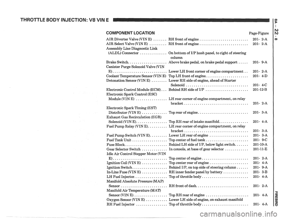
THROTTLE BODY INJECTION: V8 VIN E
COMPONENT LOCATION Page-Figure
AIR Diverter Valve (VIN E)
....... RH front of engine .........................
AIR Select Valve (VIN E) ......... RH front of engine .........................
Assembly Line Diagnostic Link
(ALDL) Connector
.............. On bottom of IIP hush panel, to right of steering
column
Brake Switch.
................... Above brake pedal, on brake pedal support .....
Canister Purge Solenoid Valve (VIN
E)
............................ Lower LH front corner of engine compartment ..
Coolant Temperature Sensor (VIN E) Top LH front of engine. .....................
Detonation Sensor (VIN E) ........ Lower RK side of engine, ahead of Starter
Solenoid
................................
Electronic Control Module (ECM) ... Behind RH side of IIP ......................
Electronic Spark Control (ESC)
Module (VIN E)
................ LH rear corner of engine compartment, on relay
................................. bracket
Electronic Spark Timing (EST)
Distributor (VIN E)
............. Top rear of engine. .........................
Exhaust Gas Recirculation (EGR)
Solenoid (VIN E).
............... Top RH rear of intake manifold. ..............
Fuel Pump Relay (VIN E). ......... LH rear corner of engine compartment, on relay
................................. bracket
Fuel Pump Switch (VIN E).
........ Lower LH rear of engine ....................
Fuel Tank Unit .................. Top center of fuel tank. .....................
Fuse Block. ..................... Behind LH side of IIP, below light switch. ......
Gear Selector Switch ............. In console, at base of gear selector ............
Idle Air Control Stepper Motor (VIN
E)
............................ Topcenterofengine ........................
Ignition Coil (VIN E) ............. Top center rear of engine ....................
Ignition Switch. ................. Behind IIP, on top side of steering column ......
In-Line Fuse (VIN E) ............. RW inner fender panel by battery .............
LW Fuel Injector. ................ Top of throttle body. .......................
Manifold Absolute Pressure (MAP)
Sensor
........................ RH front of dash. ..........................
Manifold Air Temperature (MAT)
Sensor (VIN
E) ................. Top RK rear of engine ......................
Oxygen Sensor (VIN E) ........... Lower LH side of engine, on exhaust manifold
RH Fuel Injector
................ Top of throttle body. .......................