1988 PONTIAC FIERO brake
[x] Cancel search: brakePage 337 of 1825
582.2 POWER HEAD ASSEMBLY
GENERAL DESCRIPTION
This booster is a tandem vacuum suspended unit.
In a normal operating mode, with the service brakes in
the released position, the tandem vacuum suspended
booster operates with vacuum on both sides of its
diaphragms. When the brakes are applied, air at
atmospheric pressure is admitted to one side of each
diaphragm to provide the power assist. When the
service brake is released, the atmospheric air is shut off
from the one side of each diaphragm. The air is then
drawn from the booster through the vacuum check
valve to the vacuum source.
important
e Replace all components included in repair kits
used to service this booster.
e Lubricate rubber parts with silicone grease,
provided in kits, to ease assembly.
o Do not use lubricated shop air on brake parts as
damage to rubber parts may result.
o If any hydraulic component is removed or
disconnected, it may be necessary to bleed all or
part of the brake system.
e The torque values specified are for dry,
unlubricated fasteners.
Perform service operations on a clean bench free
from all mineral oil materials.
ON-CAR SERVICE
BOOSTER ASSEMBLY
(Figure 2)
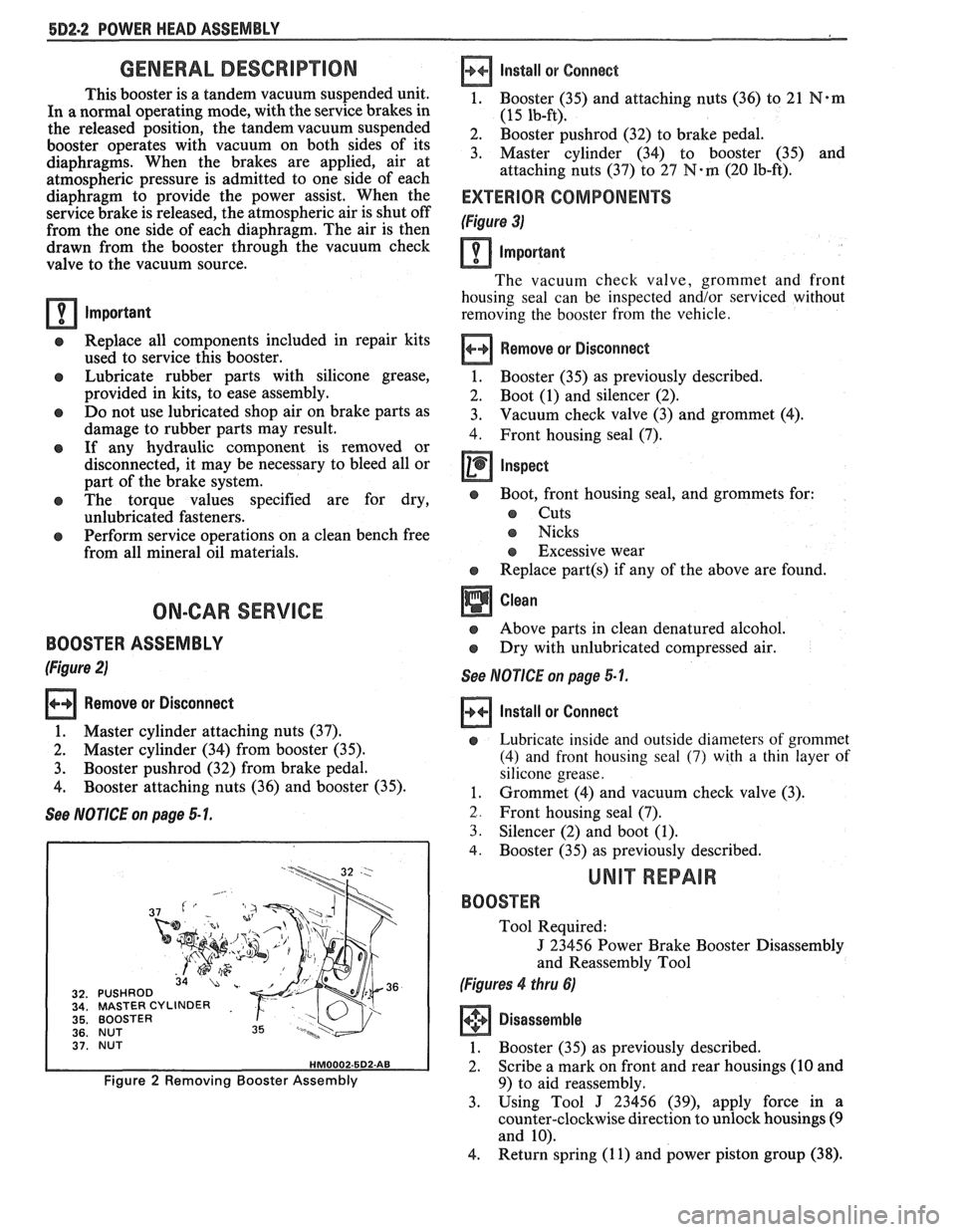
Remove or Disconnect
1. Master cylinder attaching nuts (37).
2. Master cylinder (34) from booster (35).
3. Booster pushrod (32) from brake pedal.
4. Booster attaching nuts (36) and booster (35).
See NOTICE on page 5 1.
MASTER CYLINDER
BOOSTER
NUT
BOOSTER
Figure 2 Removing Booster Assembly
Install
or Connect
1, Booster (35) and attaching nuts (36) to 21 N*m
(15 lb-ft).
2. Booster pushrod (32) to brake pedal.
3. Master cylinder (34) to booster (35) and
attaching nuts (37) to
27 N-m (20 lb-ft).
EXTERIOR COMPONENTS
(Figure 3)
Important
The vacuum check valve, grommet and front
housing seal can be inspected and/or serviced without
removing the booster from the vehicle.
Remove or Disconnect
1. Booster (35)
as previously described.
2. Boot (1) and silencer (2).
3. Vacuum check
valve (3) and grommet (4).
4. Front housing seal (7).
Inspect
e Boot, front housing seal, and grommets for:
s Cuts
s Nicks
s Excessive wear
e Replace part(s) if any of the above are found.
Above parts in clean denatured alcohol.
Dry with unlubricated compressed air.
See NOTICE on page 5-1.
Install or Connect
e Lubricate inside and outside diameters of grommet
(4) and front housing seal
(7) with a thin layer of
silicone grease.
1. Grommet (4) and vacuum check valve (3).
2. Front housing seal (7).
3. Silencer (2) and boot (1).
4. Booster (35) as previously described.
UNIT REPAIR
BOOSTER
Tool Required:
J 23456 Power Brake Booster Disassembly
and Reassembly Tool
(Figures 4 thru 6)
Disassemble
1. Booster (35) as previously described.
2. Scribe a mark on front and rear housings (10 and
9) to aid reassembly.
3. Using Tool
J 23456 (39), apply force in a
counter-clockwise direction to unlock housings
(9
and 10).
4. Return spring
(1 1) and power piston group (38).
Page 344 of 1825
SPECIFICATIONS AND SPECIAL TOOLS
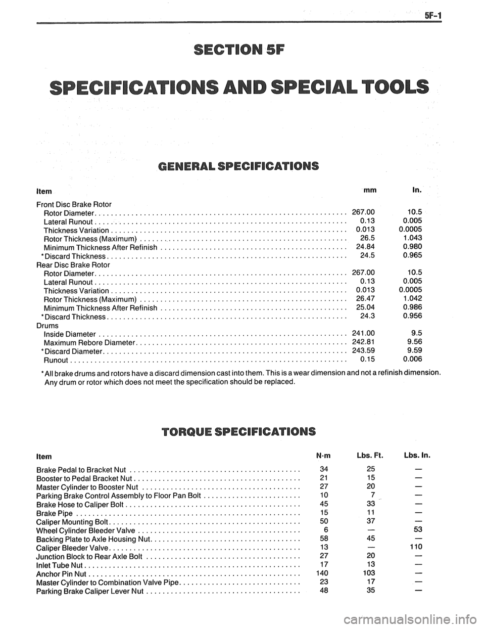
GENERAL SPECIFICATIONS
Item mm In.
Front Disc Brake Rotor
Rotor Diameter.
............................................................. 267.00 10.5
LateralRunout .............................................................. 0.13 0.005
Thicknessvariation .......................................................... 0.013 0.0005
Rotor Thickness (Maximum)
................................................... 26.5 1.043
Minimum Thickness After Refinish
.............................................. 24.84 0.980
*DiscardThickness ........................................................... 24.5 0.965
Rear Disc Brake Rotor
Rotor Diameter.
............................................................. 267.00 10.5
LateralRunout .............................................................. 0.13 0.005
Thickness Variation
.......................................................... 0.01 3 0.0005
Rotor Thickness (Maximum)
................................................... 26.47 1.042
Minimum Thickness After Refinish
.............................................. 25.04 0.986
*DiscardThickness ........................................................... 24.3 0.956
Drums
InsideDiameter ............................................................. 241.00 9.5
Maximum
Rebore Diameter. ................................................... 242.81 9.56
*Discard Diameter.
........................................................... 243.59 9.59
Runout ................................................................ 0.15 0.006
*All brake drums and rotors have a discard dimension cast into them. This is a wear dimension and not a refinish dimension.
Any drum or rotor which does not meet the specification should be replaced.
TORQUE SPECIFICATIONS
Item N-m
BrakePedaltoBracketNut .......................................... 34
Booster to Pedal Bracket Nut.
........................................ 2 1
Master Cylinder to Booster Nut
....................................... 27
Parking Brake Control Assembly to Floor Pan Bolt
........................ 10
Brake Hose to Caliper Bolt
........................................... 45
BrakePipe ....................................................... 15
Caliper Mounting Bolt.
.............................................. 50
Wheel Cylinder Bleeder Valve
........................................ 6
Backing Plate to Axle Housing Nut.
.................................... 58
Caliper Bleeder Valve.
.............................................. 13
Junction Block to Rear Axle Bolt
...................................... 27
InletTubeNut ..................................................... 17
AnchorPinNut .................................................... 140
Master Cylinder to Combination Valve Pipe.
............................. 23
Parking Brake Caliper Lever Nut
...................................... 48
Lbs. Ft. Lbs. In.
Page 345 of 1825
5F-2 SPECIFICATIONS AND SPECIAL TOOLS
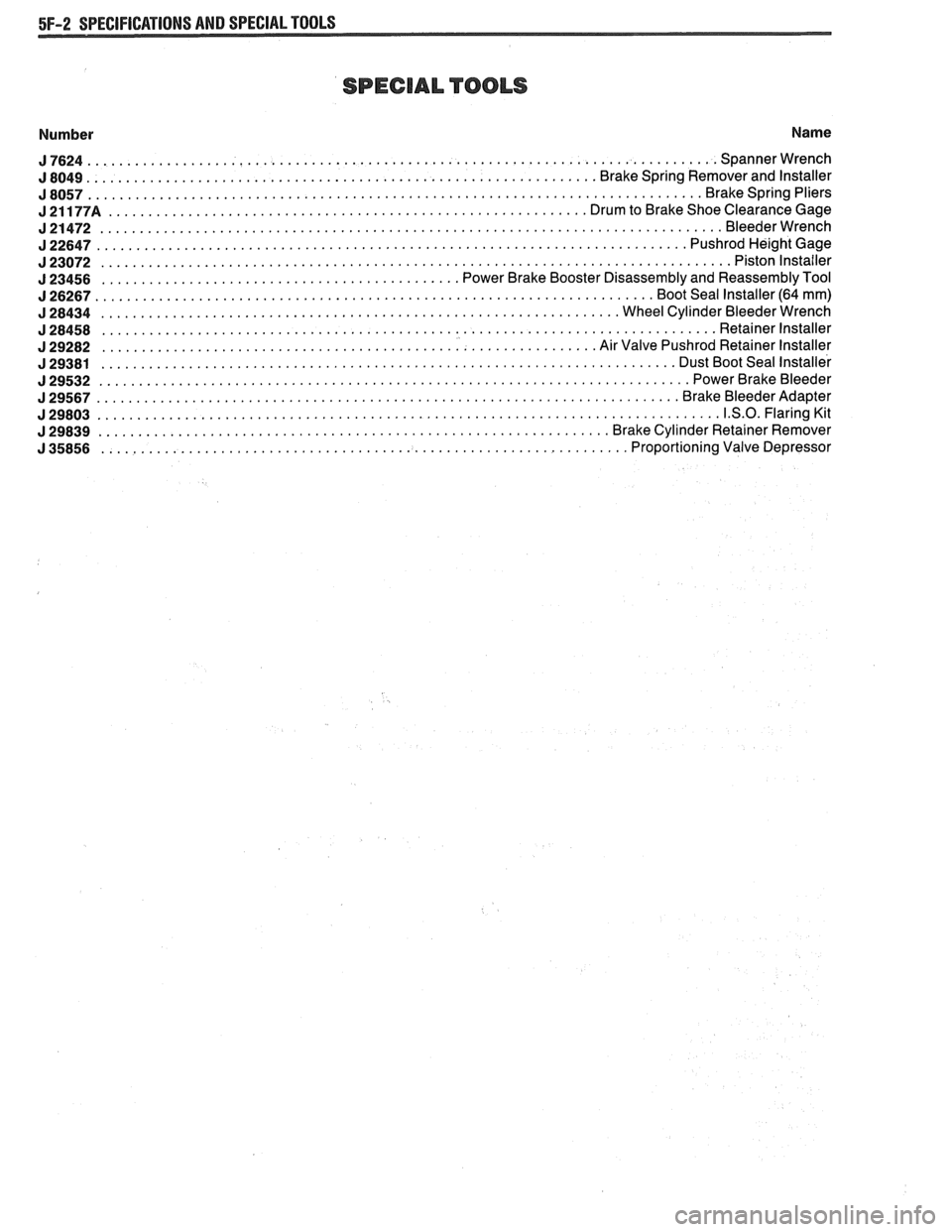
SPECIAL TOOLS
Number Name
J7624 ............................................................................... Spannerwrench
................................................................ J 8049 Brake Spring Remover and Installer
J8057 ............................................................................. Brakespringpliers
J21177A ............................................................ DrumtoBrakeShoeClearanceGage
J21472 .............................................................................. Bleederwrench
J22647 .......................................................................... PushrodHei ghtGage
J23072 ............................................................................... Pistonlnstailer
............................................. J 23456 Power Brake Booster Disassembly and Reassembly Tool
J26267 ...................................................................... BootSeallnstaller(64mm)
J28434 ................................................................. WheelCylinderBleederWrench
J28458 ............................................................................. Retainerlnstaller
.............................................................. J 29282 Air Valve Pushrod Retainer Installer
........................................................................ J 29381 Dust Boot Seal Installer
J29532 .......................................................................... PowerBrakeBleeder
J29567 ......................................................................... Br akeBleederAdapter
J29803 .............................................................................. 1.S.O.FlaringKit
................................................................ J 29839 Brake Cylinder Retainer Remover
.................................................................. J 35856 Proportioning Valve Depressor
Page 376 of 1825
2.8 LITER V-6 6A2-25
Fitting
1. Select rings comparable in size to the piston being
used.
2. Slip
the compression ring in the cylinder bore;
then press the ring down into the cylinder bore
about 6mm above ring travel. Be sure ring is
square with cylinder wall.
3. Measure the space or gap between the ends of the
ring with a feeler gage (Figure
6A2-33).
4. If
the gap between the ends of the ring is below
specifications, remove the ring and try another
for fit.
5. Fit each compression ring to the cylinder in
which it is going to be used.
6. If the pistons have not been cleaned and inspected
as previously outlined, do so.
7. Slip the outer surface of the top and second
compression ring into the respective piston ring
groove and roll the ring entirely around the
groove (Figure
6A2-34). If binding occurs at any
point, the cause should be determined. If there is
a ring groove, remove by dressing with a fine cut
file. If the binding is caused by a distorted ring,
check a new ring.
Installation
1. Install oil ring spacer in groove being sure ends
are butted and not overlapped.
2. Hold
spacer ends butted and install lower steel oil
ring rail.
3. Install upper
steel oil ring rail with gap staggered.
4. Flex
the oil ring assembly to make sure ring is
free. If binding occurs, the cause should be
detemined. If caused by ring groove, remove by
dressing groove with a fine cut file. If binding is
caused by a distorted ring, check a new ring.
5. Install second compression ring. Stagger gap
from other rings.
6. Install top compression ring with gap properly
located.
ENGINE ASSEMBLY
Removal
Disconnect battery.
Remove air cleaner.
Remove hood. Drain radiator.
Remove lower radiator hose.
Remove upper fan shroud.
Remove upper radiator hose and coolant
recovery hose.
Remove transmission cooler lines. Remove radiator.
Remove fan assembly.
Remove heater hoses.
Disconnect carburetor linkage, includes cruise
control detent cable.
Remove vacuum brake booster line.
Remove distributor cap and lay wiring aside.
Disconnect necessary wires and hoses.
Remove power steering pump and lay aside. Raise
vehicle.
Remove exhaust pipes at exhaust manifold.
Remove dust cover.
Remove converter bolts.
Disconnect starter wires.
Remove bell housing bolts.
Remove motor mount through bolts.
Disconnect fuel lines at fuel pump.
Lower vehicle. Support transmission.
Remove
A.I.R./Converter pipes bracket.
Remove engine, include removing wire from
bracket at rear left of engine.
Installation
Position engine assembly in vehicle.
Attach motor mount to engine brackets and
lower engine in place.
Remove engine lifting device.
Remove transmission floor jack.
Raise vehicle on hoist.
Install mount "through" bolts. Torque to
specifications.
Install bell housing bolts. Torque to
specifications.
On vehicles with automatic transmission, install
converter to flywheel attaching bolts. Torque to
specifications.
Install flywheel splash shield of conveter housing
cover as applicable. Torque attaching bolts to
specifications.
Install starter wires.
Connect fuel lines.
Connect exhaust pipe at manifold.
Lower vehicle on hoist.
Reinstall power steering pump, if so equipped.
Connect necessary wires and hoses.
Install radiator and fan shroud and reconnect
radiator and heater hoses.
Fill cooling system.
Fill crankcase with oil. See owner's manual for
specifications.
Install air cleaner.
Install hood.
Connect battery cables.
NOTICE: To avoid possible arcing of battery,
connect positive battery cable first.
22. Start engine, check for leaks and check timing.
CRANKSHAFT
The crankshaft can be removed while the engine
is dissasembled for overhaul, as previously outlined or
without complete disassembly.
Removal
1. With the engine removed from the vehicle,
remove the clutch assembly (if equipped) and
flywheel. Mount engine in stand and clamp
securely.
Page 385 of 1825
6A3-6 V-8 ENGINE
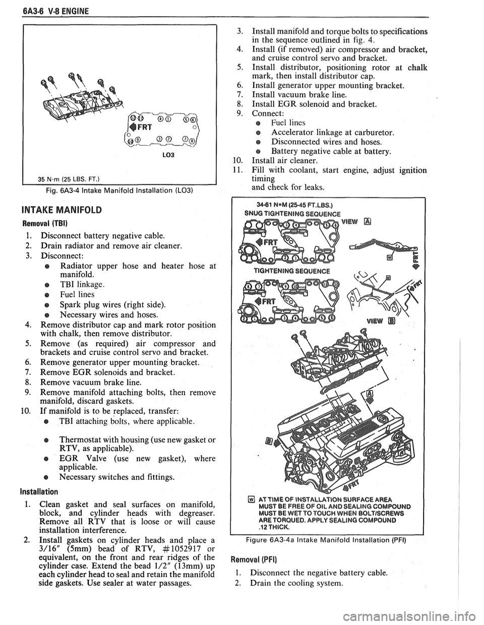
Fig. 6A3-4 Intake Manifold Installation (LO31
INTAKE MANIFOLD
Removal (TBI)
1. Disconnect battery negative cable.
2. Drain radiator and remove air cleaner.
3. Disconnect:
e Radiator upper hose and heater hose at
manifold.
e TBI linkage.
e Fuel lines
Spark plug wires (right side).
e Necessary wires and hoses.
4. Remove distributor cap and mark rotor position
with chalk, then remove distributor.
5. Remove (as required) air compressor and
brackets and cruise control servo and bracket.
6. Remove generator upper mounting bracket.
7. Remove EGR solenoids and bracket.
8. Remove vacuum brake line.
9. Remove manifold attaching bolts, then remove
manifold, discard gaskets.
10. If manifold is to be replaced, transfer:
e TBI attaching bolts, where applicable.
Thermostat with housing (use new gasket or
RTV, as applicable).
EGR Valve (use new gasket), where
applicable.
e Necessary switches and fittings.
lnstallation
1. Clean gasket and seal surfaces on manifold,
block, and cylinder heads with degreaser.
Remove all RTV that is loose or will cause
installation interference.
2. Install gaskets on cylinder heads and place a
3/16" (5mm) bead of RTV, At1052917 or
equivalent, on the front and rear ridges of the
cylinder case. Extend the bead
1/2" (13mm) up
each cylinder head to seal and retain the manifold
side gaskets. Use sealer at water passages. 3.
Install manifold and torque bolts to specifications
in the sequence outlined in
fig. 4.
4. Install (if removed) air compressor and bracket,
and cruise control servo and bracket.
5. Install distributor, positioning rotor at chalk
mark, then install distributor cap.
6. Install generator upper mounting bracket.
7. Install vacuum brake line.
8. Install EGR solenoid and bracket.
9. Connect:
Fuel lines
s Accelerator linkage at carburetor.
@ Disconnected wires and hoses.
Battery negative cable at battery.
10. Install air cleaner.
11. Fill with coolant, start engine, adjust ignition
timing
and check for leaks.
SNUG TIGHTENING SEQUENCE
WEW @
AT TIME OF INSTALUVIBN SURFACE AR- MUST BE FREE OF OIL AND 8ULlNG CQMWUIJD MUST BE Wm TO TOUCH WHEN BBLTISCRWS ARE TORQUED. APPLY SULINO GOMPOLINB
Figure 6A3-4a Intake Manifold Installation (PFI)
Removal (PFI]
1. Disconnect the negative battery cable.
2. Drain the cooling system.
Page 386 of 1825
V-8 ENGINE 6A3-7
-
3. Disconnect accelerator T.V. and cruise cables.
4. Remove air intake duct.
5. Disconnect coolant hoses at throttle body.
6. Disconnect wires at throttle body.
7. Disconnect vacuum and breather hoses at
throttle body.
8. Remove throttle body from plenum.
9. Remove distributor shield.
10. Disconnect brake vacuum hoses at plenum.
1 1. Disconnect vacuum hoses at plenum.
12. Refer to Section 6E3 for removal of:
a Plenum
Fuel Rail
a Cold Start Injector
e Runners
13. Remove distributor.
14. Disconnect EGR solenoid.
15. Disconnect all electrical wires that would
interfere.
16. Remove intake manifold bolts.
17. Remove intake manifold.
Installation
1. Clean all seal surfaces.
2. Install gaskets and place a 3/16 inch 5 (mm) bead
of RTV, No. 1052917 or
equivalent,on the front
and rear ridges of the cylinder case. Extend the
bead 1/2 inch
(13mm) up each cylinder head to
seal and retain the manifold side gaskets and
install intake manifold.
3. Torque manifold bolts to specified torque.
4. Reconnect electrical and vacuum wires.
5. Install distributor.
6. Refer to Section 6E3 for installation
of:
e Plenum
e Fuel Rail
e Cold Start Injectors
a Runners
7. Vacuum hoses at plenum.
8. Install distributor shield.
9. Install throttle body and related parts.
10. Fill cooling system.
1 1. Reconnect battery cable.
12. Start engine and look for leaks.
DIPSTICK TUBE
Removal
1.
Disconnect battery negative cable to prevent
possible contact of the dipstick tube with the
battery terminal on starter during removal.
2. Remove bolt attaching bracket to engine and
remove tube (loose fit).
lnstallation
1. Clean tube and apply sealant #I052080 or
equivalent, around tube
1/2" below bead.
2. Insert tube in block and rotate into position.
3. Install bolt (with starter brace on top of tube
bracket) and connect battery cable.
&LB9/LO3/L98
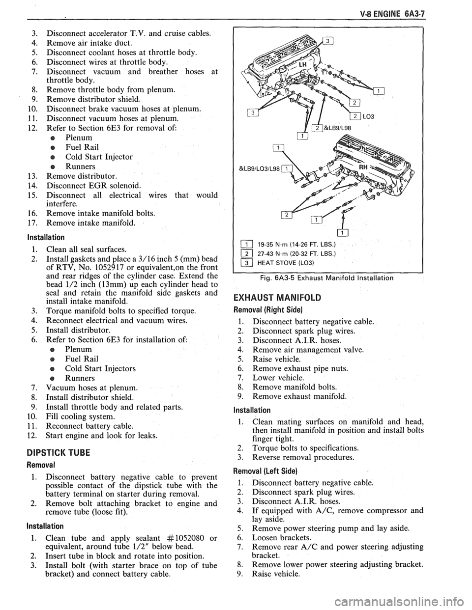
19-35 N.m (14-26 FT. LBS.)
27-43
N.m (20-32 FT. LBS.)
Fig. 6A3-5 Exhaust Manifold lnstallation
EXHAUST MANIFOLD
Removal (Right Side)
1. Disconnect battery negative cable.
2. Disconnect spark plug wires.
3. Disconnect
A.I.R. hoses.
4. Remove air management valve.
5. Raise vehicle.
6. Remove exhaust pipe nuts.
7. Lower vehicle.
8. Remove manifold bolts.
9. Remove exhaust manifold.
lnstallation
1. Clean
mating surfaces on manifold and head,
then install manifold in position and install bolts
finger tight.
2. Torque bolts to specifications.
3. Reverse removal procedures.
Removal (Left Side)
1. Disconnect battery negative cable.
2. Disconnect spark plug wires.
3. Disconnect A.I.R. hoses.
4. If equipped with
A/C, remove compressor and
lay aside.
5. Remove power steering pump and lay aside.
6. Loosen brackets.
7. Remove rear
A/C and power steering adjusting
bracket.
8. Remove lower power steering adjusting bracket.
9. Raise vehicle.
Page 387 of 1825
6A3-8 V-8 ENGINE
10. Remove exhaust pipe nuts.
1 1. Lower vehicle.
12. Remove manifold bolts.
13. Remove manifold.
Installation
1. Clean mating surfaces on manifold and head,
then install manifold in position and install bolts
finger tight.
2. Torque bolts to specifications.
3. Reverse removal procedures.
4. Adjust necessary drive belts.
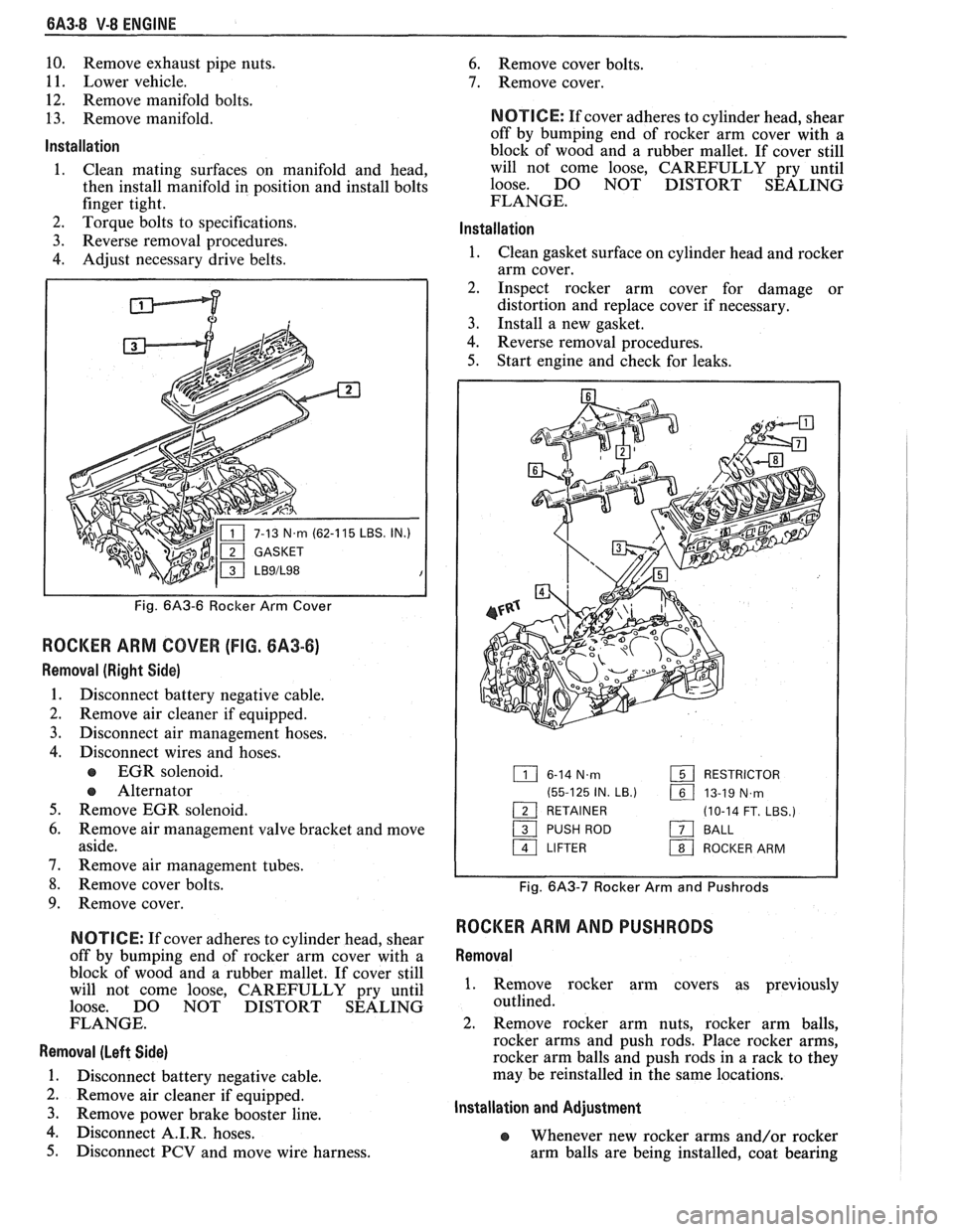
P
IN.)
Fig. 6A3-6 Rocker Arm Cover
ROCKER ARM COVER (FIG. 6A3-6)
Removal (Right Side)
1. Disconnect battery negative cable.
2. Remove air cleaner if equipped.
3. Disconnect air management hoses.
4. Disconnect wires and hoses.
EGR solenoid.
e Alternator
5. Remove EGR solenoid.
6. Remove air management valve bracket and move
aside.
7. Remove air management tubes.
8. Remove cover bolts.
9. Remove cover.
N OTI G E: If cover adheres to cylinder head, shear
off by bumping end of rocker arm cover with a
block of wood and a rubber mallet. If cover still
will not come loose, CAREFULLY pry until
loose. DO NOT DISTORT SEALING
FLANGE.
Removal (Left Side)
1. Disconnect battery negative cable.
2. Remove air cleaner if equipped.
3. Remove Power brake booster line.
4. isc connect A.I.R. hoses.
5. Disconnect PCV and move wire harness.
6. Remove cover bolts.
7. Remove cover.
NOTICE: If cover adheres to cylinder head, shear
off by bumping end of rocker arm cover with a
block of wood and a rubber mallet. If cover still
will not come loose, CAREFULLY pry until
loose. DO NOT DISTORT SEALING
FLANGE.
lnstallation
1. Clean gasket surface on cylinder head and rocker
arm cover.
2. Inspect rocker arm cover for damage or
distortion and replace cover if necessary.
3. Install a new gasket.
4. Reverse removal procedures.
5. Start engine and check for leaks.
6-14 N.m RESTRICTOR
(55-125 IN.
LB.) 161 13-19 N,rn - 1 RETAINER (10-14 FT. LBS.)
/ PUSH ROD a BALL
a LIFTER 1 ROCKER ARM
Fig. 6A3-7 Rocker Arm and Pushrods
ROCKER ARM AND PUSHRODS
Removal
1. Remove rocker arm covers as previously
outlined.
2. Remove rocker arm nuts, rocker arm balls,
rocker arms and push rods. Place rocker arms,
rocker arm balls and push rods in a rack to they
may be reinstalled in the same locations.
Installation and Adjustment
e Whenever new rocker arms and/or rocker
arm balls are being installed, coat bearing
Page 406 of 1825
V-8 ENGINE 6A3-27
3. When finish honing
a cylinder bore to fit a piston,
the hone should be moved up and down at a
sufficient speed to obtain very fine uniform
surface finish marks in a cross-hatch pattern of
approximately
45" to 65" included angle. The
finish marks should be clean but not sharp, free
from imbedded particles and torn or folded
metal.
4. Permanently mark
the piston for the cylinder to
which it has been fitted and proceed to hone
cylinders and fit the remaining pistons.
NOTICE: Handle the pistons with care and do not
attempt to force them through the cylinder until
the cylinder has been honed to correct size as this
type piston can be distorted through careless
handling.
5. Thoroughly
clean the bores with hot water and
detergent. Scrub well with a stiff bristle brush and
rinse thoroughly with hot water. It is extremely
essential that a good cleaning operation be
performed. If any of the abrasive material is
allowed to remain in the cylinder bores, it will
rapidly wear the new rings and cylinder bores in
addition to the bearings lubricated by the
contaminated oil, the bores should be swabbed
and then wiped with a clean dry cloth. Cylinder
should not be cleaned with kerosene or gasoline.
Clean the remainder of the cylinder block to
remove the excess material spread during the
honing operation.
Piston Selection
1. Check USED piston to cylinder bore clearance as
follows:
a. Measure
the "Cylinder Bore Diameter"
with a telescope gage
"2-1/2" (64mm) from
top of cylinder bore").
b. Measure
the
"Piston Diameter" (at skirt
across center line of piston pin).
c. Subtract
piston diameter from cylinder bore
diameter to determine "Piston to Bore
Clearance".
d. Determine if piston to bore clearance is in
the acceptable range.
2. If
used piston is not acceptable, check Piston Size
Chart and determine if a new piston can be
selected to fit cylinder bore within the acceptable
range.
3. If
cylinder bore must be reconditioned, measure
new piston diameter (across center line of piston
pin) then hone cylinder bore to correct clearance
(preferable range).
4. Mark the piston to identify the cylinder for which
it was fitted.
OIL FILTER BYPASS VALVE
Inspection and Replacement
With the oil filter removed, check the spring and
fibre valve for operation. Inspect for a cracked or
broken valve. If replacement is necessary, the oil filter
adapter and bypass valve assembly must be replaced as an
assembly. Clean valve chamber in cylinder block
thoroughly. Torque retaining screws to specifications.
ENGINE ASSEMBLY
Removal
1. Disconnect battery.
2. Remove air cleaner.
3. Remove hood.
4. Drain radiator.
5. Remove lower radiator hose.
6. Remove upper fan shroud.
7. Remove upper radiator hose and coolant
recovery hose.
8. Remove transmission cooler lines.
9. Remove radiator.
10. Remove fan assembly.
1 1. Remove heater hoses.
12. Disconnect
carburetor linkage, includes cruise
control detent cable.
13. Remove vacuum brake booster line.
14. Remove
distributor cap and lay wiring aside.
15. Disconnect necessary wires and hoses.
16. Remove power steering
pump and lay aside.
17. Raise vehicle.
18. Remove exhaust
pipes at exhaust manifold.
19. Remove dust cover.
20. Remove converter bolts.
2 1. Disconnect starter wires.
22. Remove bell housing bolts.
23. Remove
motor mount through bolts.
24. Disconnect fuel lines
at fuel pump.
25. Lower vehicle.
26. Support transmission.
27. Remove
A.I.R./Converter pipe bracket.
28. Remove engine, include removing wire
from
bracket at rear left of engine.
Installation
1. Position engine
assembly in vehicle.
2. Attach
motor mount to engine brackets and
lower engine in place.
3. Remove engine lifting device.
4. Remove transmission floor jack.
5. Raise vehicle on hoist.
6. Install mount "through" bolts. Torque to
specifications.
7. Install bell housing bolts. Torque to
specifications.
8. On vehicles with automatic transmissions, install
I
converter to flywheel attaching bolts. Torque to
specifications.
9. Install flywheel splash shield of converter
housing cover as applicable. Torque attaching
bolts to specifications.
I
10. Install starter wires.
1 1. Connect fuel lines.
12. Connect exhaust pipe at manifold.
13. Lower vehicle on hoist.
14. Reinstall power steering pump, if so equipped.
15. Connect necessary wires and hoses.