Page 436 of 513

ENGINE
r
Ignition
switJ
c
o
iArm
ture
j
i
i
VC2
P
tP2
d
I
I
I
PI
I
ll
Rl
L
I
I
lRJ
t
R
I
Field
e
I
I
I
I
Ps
I
1
I
I
n
I
coil
M
4
i
f
I
L
1
J
Alternator
Voltage
regulator
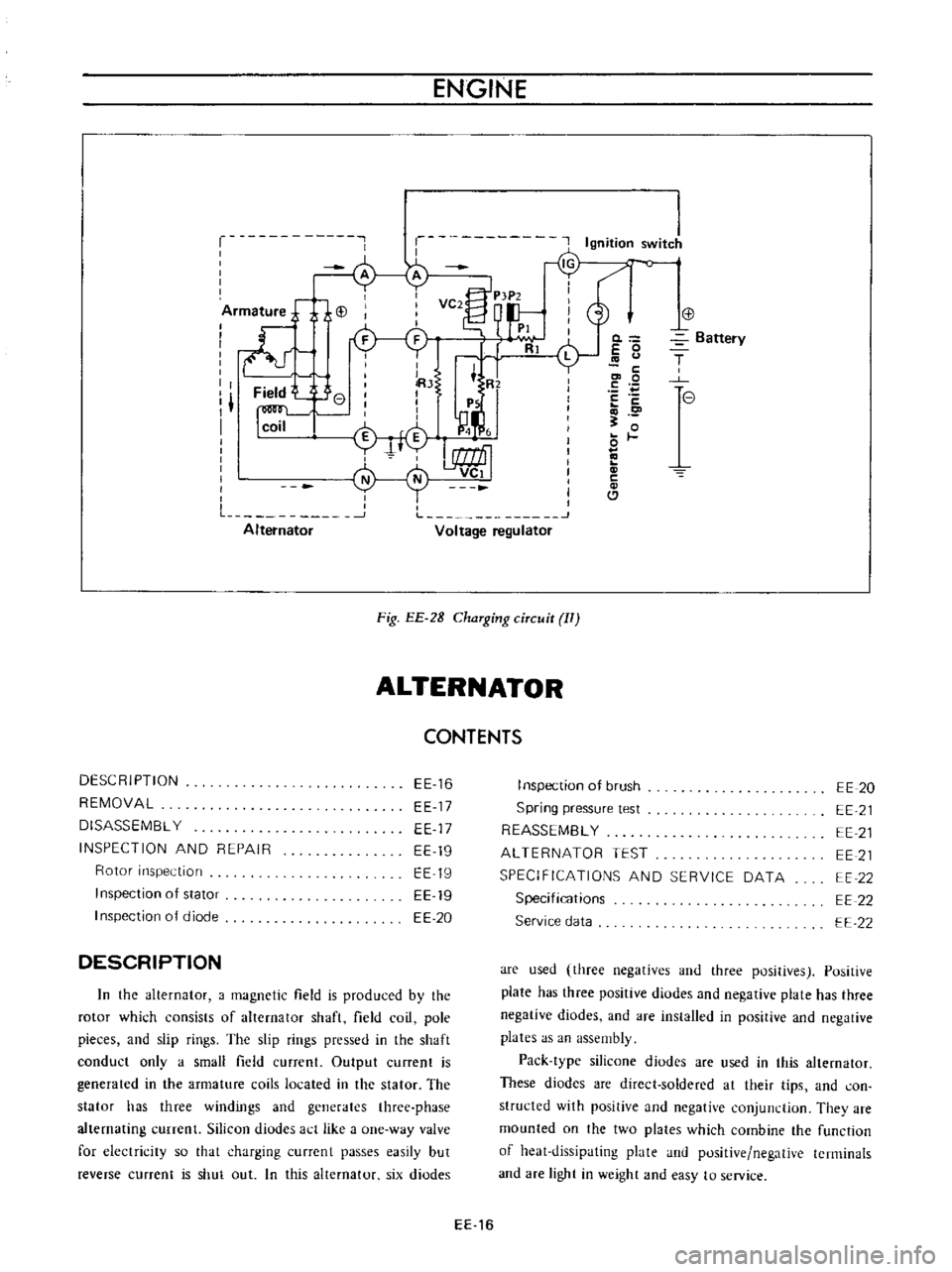
Fig
EE
2B
ChaTging
ciTcuit
II
ALTERNATOR
CONTENTS
DESCRIPTION
REMOVAL
DISASSEMBL
Y
INSPECTION
AND
REPAIR
Rotor
inspection
Inspection
of
stator
I
nspection
of
diode
EE
16
EE
17
EE
17
EE
19
EE
19
EE
19
EE
20
DESCRIPTION
In
the
alternator
a
magnetic
field
is
produced
by
the
rotor
which
consists
of
alternator
shaft
field
coil
pole
pieces
and
slip
rings
The
slip
rings
pressed
in
the
shaft
conduct
only
a
small
field
current
Output
current
is
generated
in
the
armature
coils
located
in
the
stator
The
stator
has
three
windings
and
generates
three
phase
alternating
currenl
Silicon
diudes
act
like
a
one
way
valve
for
electricity
so
that
charging
currcnt
passes
easily
but
reverse
current
is
shut
out
In
this
alternator
six
diodes
0
E
0
c
co
0
E
c
o
0
c
Cl
Battery
T
e
I
nspection
of
brush
Spring
pressure
test
REASSEMBL
Y
ALTERNATOR
TEST
SPECIFICATIONS
AND
SERVICE
DATA
Specifications
Service
data
EE
20
EE
21
EE
21
EE
21
EE
22
EE
22
EE
22
are
used
three
negatives
and
three
positives
Positive
plate
has
three
positive
diodes
and
negative
plate
has
three
negative
diodes
and
are
installed
in
positive
and
negative
plates
as
an
assembly
Pack
type
silicone
diodes
are
used
in
this
alternator
These
diodes
are
direct
soldered
at
their
tips
and
con
structed
with
positive
and
negative
conjunction
They
are
mounted
on
the
two
plates
which
combine
the
function
of
heat
dissipating
plate
and
positive
negative
terminals
and
are
light
in
weight
and
easy
to
service
EE
16
Page 446 of 513

ENGINE
at
4
to
5
V
Use
i
f
DC
voltmeter
and
set
up
a
circuit
as
shown
in
Figure
EE
56
EEQ58
L
W
R
IG
Will
r
AI
W
lli
r
N
Y
vge
I
JJ
Rtl
ublOr
I
I
Spanner
Cross
head
screwdriver
I
I
Adjusting
screw
Lock
nut
Vollm
lcl
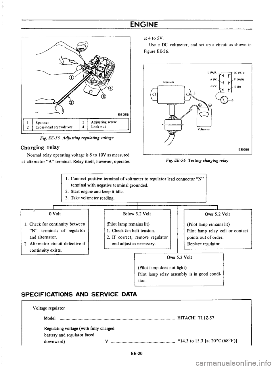
Fig
EE
55
Adjusting
Tegulating
voltage
Charging
relay
Normal
relay
operating
voltage
is
8
to
10V
as
measured
at
alternator
A
terminal
Relay
itself
however
operates
EE059
Fig
EE
56
Testing
chaTging
Telay
Connect
positive
terminal
of
voltmeter
to
regulator
lead
connector
N
terminal
with
negative
terminal
grounded
2
Start
engine
and
keep
it
idle
3
Take
voltmeter
reading
o
Volt
Below
5
2
Volt
I
Over
5
2
Volt
I
Check
for
continuity
between
N
terminals
of
regulator
and
alternator
2
Alternator
circuit
defective
if
continuity
exists
pilot
lamp
remains
lit
I
Check
fan
belt
tension
2
If
correct
remove
regulator
and
adjust
as
necessary
Pilot
lamp
remains
lit
Pilot
lamp
relay
coil
or
contact
points
out
of
order
Replace
regulator
Over
5
2
Volt
Pilot
lamp
does
not
light
Pilot
lamp
relay
assembly
is
in
good
condi
tion
SPECIFICATIONS
AND
SERVICE
DATA
Voltage
regulator
Model
HITACHI
TLl
Z
57
Regulating
voltage
with
fully
charged
battery
and
regulator
faced
downward
V
14
3
to
15
3
at
200C
680F
EE
26
Page 448 of 513

Low
output
Excessive
output
Regulator
Wiring
Alternator
Regula
tor
Wiring
Alternator
Regulatur
ENGINE
Faulty
voltage
regulator
point
con
tact
Broken
cable
or
disconnection
of
charging
cireui
t
Sticking
brushes
Low
brush
spring
tension
Dirty
slip
rings
Partially
shorted
ground
or
open
stator
coil
Partially
shorted
or
grounded
rotor
coil
Defective
diode
Loose
or
worn
fan
belt
Improper
voltage
regulator
adjust
ment
Faulty
voltage
regulator
point
con
tact
Defective
operation
Faulty
charging
circuit
lead
wire
connection
Loose
battery
terminal
Short
circuited
or
broken
neutral
wire
Improper
voltage
regulator
adjust
ment
Defective
operation
Improper
charge
relav
adjustment
detective
operation
and
or
faulty
point
contact
EE
28
Repair
or
replace
the
regulatur
Repair
or
replace
Correct
or
replace
brushes
if
neces
sary
Correct
or
replace
brush
Clean
Replace
the
stator
Replace
the
rotor
Replace
the
diode
assembly
Retighten
or
replace
the
belt
Check
the
voltage
regulator
op
eration
and
repair
or
replace
as
required
Repair
or
replace
the
regulator
Repair
or
replace
Retighten
Replace
the
wire
Check
the
voltage
regulator
op
eration
and
repair
or
replace
as
required
Check
the
charge
relay
operation
and
repair
or
replace
as
required
Page:
< prev 1-8 9-16 17-24