1973 DATSUN B110 charging
[x] Cancel search: chargingPage 420 of 513
DATSUN
1200
MODEL
B
11
0
SERIES
L
NISSAN
I
NISSAN
MOTOR
CO
LTD
TOKYO
JAPAN
SECTION
EE
ENGINE
ELECTRICAL
SYSTEM
BATTERY
STARTING
MOTOR
CHARGING
CIRCUIT
ALTERNATOR
REGULATOR
IGNITIO
N
CIRCUIT
DISTRIBUTOR
IGNITION
COIL
SPARK
PLUG
EEl
EE
3
EE
15
EE
16
EE
23
EE
29
EE
29
EE
36
EE
37
Page 421 of 513
ENGINE
ElECTRICAL
SYSTEM
BATTERY
CONTENTS
REMOVAL
CHECKING
ELECTROLYTE
LEVEL
CHECKING
SPECIFIC
GRAVITY
EE
1
EE
l
EE
1
REMOVAL
Disconnect
the
negative
terminal
first
and
then
the
positive
terminal
2
Remove
the
retainer
nuts
and
take
off
retainer
3
Release
retainer
bolts
and
remove
battery
CHECKING
ELECTROLYTE
LEVEL
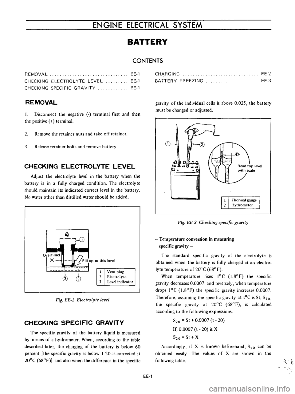
Adjust
the
electrolyte
level
in
the
battery
when
the
battery
is
in
a
fully
charged
condition
The
electrolyte
hould
maintain
its
indicated
correct
level
in
the
battery
N
water
other
than
distilled
water
should
be
added
Q
cD
I
1
Vent
plug
2
Electrolvte
3
Level
indicator
Fig
EE
1
ElectTolyte
level
CHECKING
SPECIFIC
GRAVITY
The
specific
gravity
of
the
battery
liquid
is
measured
by
means
of
a
hydrometer
When
according
to
the
table
described
later
the
charging
of
the
battery
is
below
60
percent
the
specific
gravity
is
below
1
20
as
corrected
at
200e
680F
and
also
when
the
difference
in
the
specific
CHARGING
BATTERY
FREEZING
EE
2
EE
3
gravity
of
the
individual
cells
is
above
0
025
the
battery
must
be
changed
or
adjusted
tl
f
ead
p
level
jSCale
2
II
It
I
TheTmat
gauge
I
2
Hydrometer
Fig
EE
2
Checking
specific
gTavity
Temperature
conversion
in
measuring
specific
gravity
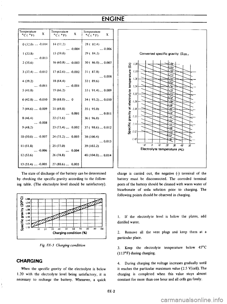
The
standard
specific
gravity
of
the
electrolyte
is
obtained
when
the
battery
is
fully
charged
at
an
electro
lyte
temperature
of
200
e
680
F
When
temperature
rises
loe
1
80F
the
specific
gravity
decreases
0
0007
and
reversely
when
temperature
drops
loe
I
ROF
the
specific
gravity
increases
0
0007
Therefore
assuming
the
specific
gravity
at
tOe
is
St
S20
the
specific
gravity
at
200e
680F
is
calculated
according
to
the
following
expressions
S
o
St
0
0007
t
20
If
0
0007
t
20
is
X
S
o
St
X
Accordingly
if
X
is
known
beforehand
S
o
can
be
obtained
easily
The
values
of
X
are
shown
in
the
following
table
EE
1
Page 422 of 513
ENGINE
Temperature
Oc
of
Temperature
C
F
x
Temperature
Oc
F
x
0
32
0
0
014
14
572
28
82
4
0
004
0
006
33
8
IS
59
0
19
I
84
2
0
013
2
35
6
16
60
8
0
003
30
86
0
0
007
3
37
4
0
012
17
61
6
0
001
31
87
8
0
008
4
39
2
18
64
4
32
89
6
0
011
0
001
5
41
0
19
66
2
33
91
4
0
009
6
42
8
0
010
20
68
0
0
34
93
2
0
010
7
44
6
0
009
21
69
8
35
95
0
0
001
0
01l
8
46
4
22
71
6
36
96
8
0
008
9
48
2
23
73
4
0
002
37
98
6
0
012
10
50
0
0
007
24
75
2
0
003
38
100
4
0
013
II
51
8
25
77
0
39
t02
2
0
006
0
004
12
53
6
16
78
8
40
104
0
0
Ot4
13
55
4
0
005
27
80
6
0
005
The
state
of
discharge
of
the
battery
can
be
determined
by
checking
the
specific
gravity
according
to
the
follow
ing
table
The
electrolyte
level
should
be
satisfactory
U
tn
l
k
1
I
P
I
IZf
I
r7
42
I
bt
7
J
I
I
11
0
I
M
I
L
J
I
10
20
30
0
50
60
70
aD
90
100
Charging
condition
Fig
EE
3
Charging
condition
CHARGING
When
the
specific
gravity
of
he
electrolyte
is
below
1
20
with
the
electrolyte
level
being
satisfactory
it
is
necessary
to
recharge
the
battery
Whenever
a
quick
x
Converted
specific
gravity
520
V
9d
f
o
1
28
u
1
6
c
E
1
24
l
22
o
0
U5
S
I
1
1
2
1
10
1
NON
M
i
Electrolyte
temperature
lOCI
charge
is
carried
out
the
negative
terminal
of
the
battery
must
be
disconnected
The
corroded
terminal
posts
of
the
battery
should
be
cleaned
with
warm
water
of
bicarbonate
of
soda
solution
prior
to
charging
The
following
points
should
be
observed
in
charging
If
the
electrolyte
level
is
below
the
plates
add
distilled
water
2
Remove
all
the
vent
plugs
and
keep
them
at
a
particular
place
3
Keep
the
electrolyte
temperature
below
450C
l130F
during
charging
4
During
charging
the
voltage
increases
gradually
until
it
reaches
the
particular
maximum
value
2
5
Vice
II
The
charging
is
completed
when
this
value
stays
almost
constant
for
more
than
one
hour
and
all
cells
gas
freely
EE
2
Page 423 of 513
ENGINE
ElECTRICAL
SYSTEM
5
If
the
specific
gravity
is
above
1
260
200C
or
680F
after
charging
adjust
it
by
adding
distilled
water
6
Keep
any
open
flame
away
from
the
place
where
the
battery
is
being
charged
7
Replace
vent
plugs
and
clean
the
upper
face
of
the
battery
after
charging
BATTERY
FREEZING
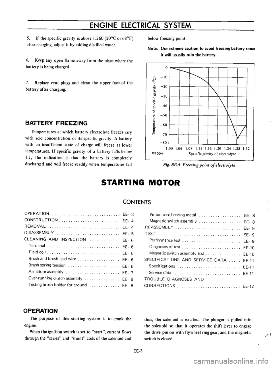
Temperatures
at
which
battery
electrolyte
freezes
vary
with
acid
concentration
or
its
specific
gravity
A
battery
with
an
insufficient
state
of
charge
will
freeze
at
lower
temperatures
If
specific
gravity
of
a
battery
falls
below
I
I
the
indication
is
that
the
battery
is
completely
discharged
and
will
freeze
readily
when
temperatures
fall
below
freezing
point
Note
Use
extreme
caution
to
avoid
freezing
battery
since
it
will
usually
ruin
the
battery
o
I
I
1
G
10
I
1
o
i
20
I
u
30
I
I
0
40
I
0
SO
I
60
0
I
E
f
o
70
I
80
1
00
1
04
1
08
I
12
1
16
20
24
1
28
1
32
E
E004
Specific
gravity
of
electrolyte
Fig
EE
4
FTeezing
point
of
electrolyte
STARTI
NG
MOTOR
CONTENTS
OPERATION
CONSTRUCTION
REMOVAL
DISASSEMBL
Y
CLEANING
AND
INSPECTION
Terminal
Field
coil
Brush
and
brush
lead
wire
Brush
spring
tension
Armature
assembly
Over
running
clutch
assembly
Testing
brush
holder
for
ground
EE
3
EE
4
EE
4
EE
5
EE
6
EE
6
EE
6
EE
6
EE
6
EE
7
EE
8
EE
8
OPERATION
The
purpose
of
this
starting
system
is
to
crank
the
engine
When
the
ignition
switch
is
set
to
start
current
flows
through
the
series
and
shunt
coils
of
the
solenoid
and
Pinion
case
bearing
metal
Magnetic
switch
assembly
REASSEMBL
Y
TESr
Performance
test
Diagnoses
of
test
Magnetic
switch
assembly
test
SPECIFICATIONS
AND
SERVICE
DATA
Specifications
Service
data
TROU8LE
DIAGNOSES
AND
CORRECTIONS
EE
8
EE
8
EE
9
EE
9
EE
g
EE
10
EE
10
EE
11
EE
11
EE
11
EE
12
thus
the
solenoid
is
excited
The
plunger
is
pulled
into
the
solenoid
so
that
it
operates
the
shift
lever
to
engage
the
drive
pinion
with
flywheel
ring
gear
and
the
magnetic
switch
is
closed
EE
3
Page 432 of 513

ENGINE
Arma
ture
shaft
Outer
diameter
Pinion
side
mm
in
12
950
to
12
968
0
5082
to
0
5105
11
450
to
II
468
0
4507
to
0
4515
0
1
0
0039
0
08
0
0031
Rear
end
mm
in
Wear
limit
Bend
limit
mm
in
mm
in
Gap
1
between
the
pinion
front
edge
and
the
pinion
stopper
mm
in
0
3
to
1
5
0
0118
to
0
0591
Magnetic
switch
Coil
resistance
Series
cuil
Q
Shunt
coil
n
Plunger
L
dimension
mm
in
0
3
at
20De
68UF
0
9
at
ooe
680F
317t032
3
l
248
to
1
272
TROUBLE
DIAGNOSES
AND
CORRECTIONS
12
950
to
12
968
0
5082
to
0
5105
11
450
to
II
468
0
4507
to
0
4515
l
0
1
0
0039
0
08
0
0031
0
3
to
1
5
0
0118
to
0
0591
0
3
at
20De
680Fl
0
9
at
200e
680F
317
to
32
3
l
248
to
I
272
Troubles
Trouble
location
Causes
Remedies
Starting
motor
will
not
operate
No
magnetic
switch
Battery
Defective
battery
Replace
battery
operating
sound
Over
discharging
Measure
specific
gravity
of
e
Ie
ctrolyte
and
ch
lrge
or
replace
the
battery
Ignition
switch
Defective
contact
Correct
or
replace
ig
nition
switch
Wiring
Faulty
starting
motor
grounding
Correct
Faulty
battery
grounding
Correct
Broken
or
disconnected
cable
Correct
or
replace
EE
12
Page 433 of 513
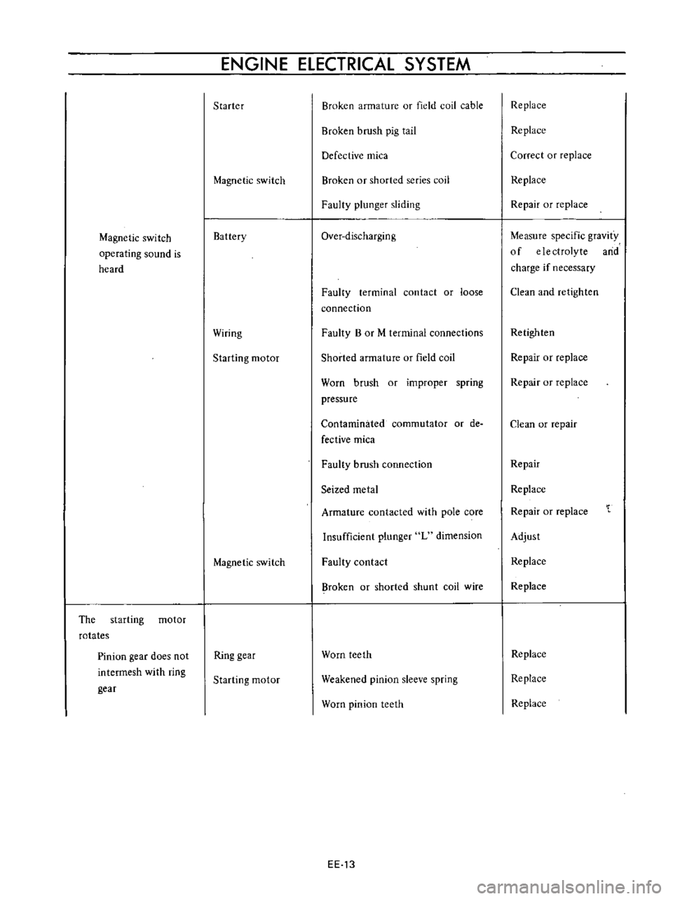
Magnetic
switch
operating
sound
is
heard
The
starting
motor
rotates
Pinion
gear
does
not
intermesh
with
ring
gear
ENGINE
ELECTRICAL
SYSTEM
Starter
Magnetic
switch
Battery
Wiring
Starting
motor
Magnetic
switch
Ring
gear
Starting
motor
Broken
armature
or
field
coil
cable
Broken
brush
pig
tail
Defective
mica
Broken
or
shorted
series
coil
Faulty
plunger
sliding
Over
discharging
Faulty
terminal
contact
or
loose
connection
Faulty
B
or
M
terminal
connections
Shorted
armature
or
field
coil
Worn
brush
or
improper
spring
pressure
Contaminated
commutator
or
de
fective
mica
Faulty
brush
connection
Seized
metal
Armature
contacted
with
pole
core
Insufficient
plunger
L
dimension
Faulty
contact
Broken
or
shorted
shunt
coil
wire
Worn
teeth
Weakened
pinion
sleeve
spring
Worn
pinion
teeth
EE
13
Replace
Replace
Correct
or
replace
Replace
Repair
or
replace
Measure
specific
gravity
of
electrolyte
arid
charge
if
necessary
Clean
and
retighten
Retighten
Repair
or
replace
Repair
or
replace
Clean
or
repair
Repair
Replace
Repair
or
replace
Adjust
Replace
Replace
Replace
Replace
Replace
Page 434 of 513

Pinion
intermeshes
with
ring
gear
Starting
motor
rotates
and
pinion
intermeshes
with
ring
gear
but
ro
tation
is
too
slow
When
starting
switch
is
set
to
OFF
the
start
ing
motor
does
not
stop
Starting
motor
Battery
Wiring
Ignition
switch
Starting
motor
Ignition
switch
Magnetic
switch
Starting
motor
ENGINE
Faulty
pinion
sliding
Dropped
off
lever
pin
Excessive
plunger
L
dimension
Defective
over
running
clutch
Over
discharging
Improper
or
loose
terminal
contact
Improperly
tightened
connection
Rough
contact
surface
Shorted
armature
coil
or
field
coil
Worn
brush
or
insufficient
spring
pressure
Contaminated
commutator
or
im
proper
brush
contact
Defective
mica
Lack
of
metal
lubrication
Armature
contacted
with
pole
core
Faulty
returning
Seized
contact
Shorted
coil
Faulty
plunger
sliding
Pinion
does
not
disengage
from
the
ring
gear
smoothly
Pinion
spline
does
not
disengage
smoothly
Seized
pinion
metal
EE
14
Repair
Repair
Adjust
Replace
Charge
battery
Repair
and
retighten
Retighten
Repair
or
replace
Repair
or
replace
Repair
or
replace
Repair
Repair
Repair
or
replace
Repair
or
replace
Replace
Replace
Replace
Replace
Repair
or
replace
Repair
or
replace
Replace
Page 435 of 513
ENGINE
ElECTRICAL
SYSTEM
CHARGING
CIRCUIT
IGNITION
1
i
n
ITCH
r
B
i
i
vel
oU
ARMATURE
lip
J
l
t
lJ
FIEL
Df
e
I
I
3
2
I
u
P
5
0
IL
U
p
P
f
H
i
I
I
L
J
L
J
ALTERNATOR
VOL
TAGE
REGULATOR
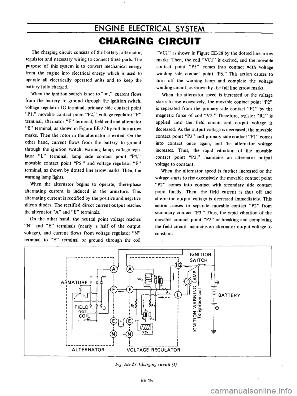
The
charging
circuit
consists
of
the
battery
alternator
regulator
and
necessary
wiring
to
connect
these
parts
The
purpose
of
this
system
is
to
convert
mechanical
energy
from
the
engine
into
electrical
energy
which
is
used
to
operate
all
electrically
operated
units
and
to
keep
the
battery
fully
charged
When
the
ignition
switch
is
set
to
on
current
flows
from
the
battery
to
ground
through
the
ignition
switch
voltage
regulator
IG
terminal
primary
side
contact
point
PI
movable
contact
point
P2
voltage
regulator
F
terminal
alternator
F
terminal
field
coil
and
alternator
E
terminal
as
shown
in
Figure
EE
27
by
full
line
arrow
marks
Then
the
rotor
in
the
alternator
is
exited
On
the
other
hand
current
flows
from
the
battery
to
ground
through
the
ignition
switch
warning
lamp
voltage
regu
lator
L
terminal
lamp
side
contact
point
P4
movable
contact
point
PS
and
voltage
regulator
E
terminal
as
shown
by
dotted
line
arrow
marks
Then
the
warning
lamp
ligh
ts
When
the
alternator
begins
to
operate
three
phase
alternating
current
is
induced
in
the
armature
This
alternating
current
is
rectified
by
the
positive
and
negative
silicon
diodes
The
rectified
direct
current
output
reaches
the
alternator
A
and
E
terminals
On
the
other
hand
the
neutral
point
voltage
reaches
N
and
E
terminals
nearly
a
half
of
the
output
voltage
and
current
flows
from
voltage
regulator
N
terminal
to
E
terminal
or
ground
through
the
coil
VCI
as
shown
in
Figure
EE
28
by
the
dolled
line
arrow
marks
Then
the
coil
vc
I
is
excited
and
the
movable
contact
point
P5
comes
into
contact
with
voltage
winding
side
contact
point
P6
This
action
causes
to
turn
off
the
warning
lamp
and
complete
the
voltage
winding
circuit
as
shown
by
the
ullline
arrow
marks
When
the
alternator
speed
is
increased
or
the
voltage
starts
to
rise
excessively
the
movable
contact
point
P2
is
separated
from
the
primary
side
contact
P
1
by
the
magnetic
force
of
coil
V2
Therefore
register
RI
is
applied
into
the
field
circuit
and
output
voltage
is
decreased
As
the
outpu
t
voltage
is
decreased
the
movable
contact
point
P2
and
primary
side
contact
PI
comes
into
contact
once
again
and
the
alternator
voltage
increases
Thus
the
rapid
vibration
of
the
movable
contact
point
P2
maintains
an
alternator
output
voltage
to
constant
When
the
alternator
speed
is
further
increased
or
the
voltage
starts
to
rise
excessively
the
movable
contact
point
P2
comes
into
contact
with
secondary
side
contact
point
finally
Then
the
field
current
is
shut
off
and
alternator
output
voltage
is
decreased
immediately
This
action
causes
to
separate
movable
contact
P2
from
secondary
contact
P3
Thus
the
rapid
vibration
of
the
movable
contact
point
P2
or
breaking
and
completing
the
field
circuit
maintains
an
alternator
output
voltage
to
constant
j
T
SA
TIERY
I
l
e
7
Fig
EE
27
ChaTging
ciTcuit
1
EE
15