2009 SUBARU TRIBECA check engine
[x] Cancel search: check enginePage 1891 of 2453
ME(H6DO)-25
Engine Oil Pressure
MECHANICAL
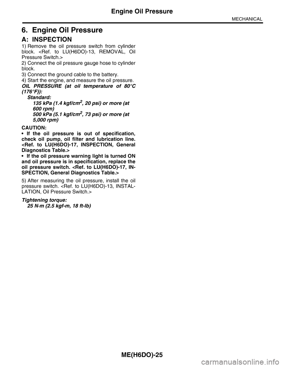
6. Engine Oil Pressure
A: INSPECTION
1) Remove the oil pressure switch from cylinder
block.
2) Connect the oil pressure gauge hose to cylinder
block.
3) Connect the ground cable to the battery.
4) Start the engine, and measure the oil pressure.
OIL PRESSURE (at oil temperature of 80°C
(176°F)):
Standard:
135 kPa (1.4 kgf/cm2, 20 psi) or more (at
600 rpm)
500 kPa (5.1 kgf/cm2, 73 psi) or more (at
5,000 rpm)
CAUTION:
•If the oil pressure is out of specification,
check oil pump, oil filter and lubrication line.
•If the oil pressure warning light is turned ON
and oil pressure is in specification, replace the
oil pressure switch.
5) After measuring the oil pressure, install the oil
pressure switch.
Tightening torque:
25 N·m (2.5 kgf-m, 18 ft-lb)
Page 1894 of 2453
ME(H6DO)-28
Valve Clearance
MECHANICAL
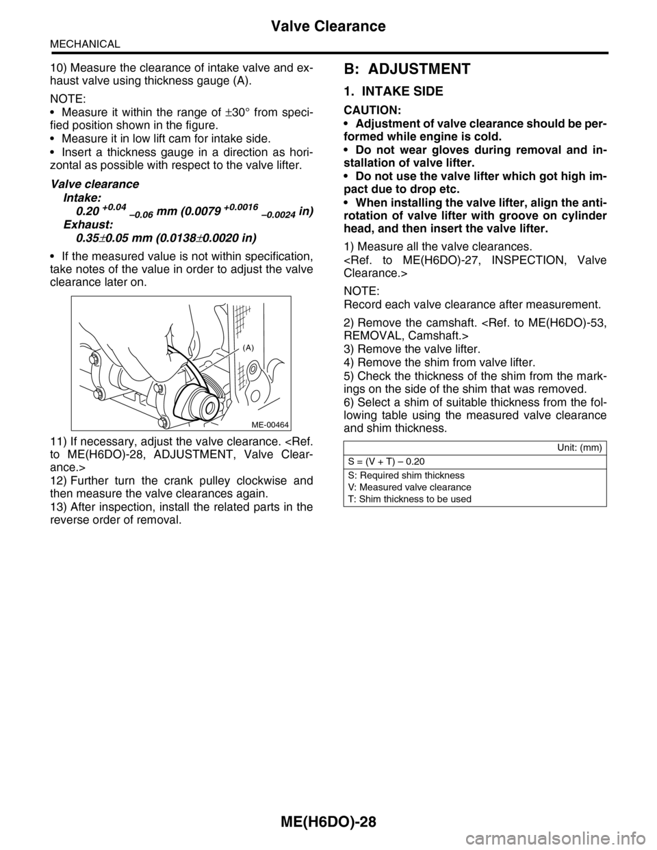
10) Measure the clearance of intake valve and ex-
haust valve using thickness gauge (A).
NOTE:
•Measure it within the range of ±30° from speci-
fied position shown in the figure.
•Measure it in low lift cam for intake side.
•Insert a thickness gauge in a direction as hori-
zontal as possible with respect to the valve lifter.
Valve clearance
Intake:
0.20 +0.04 –0.06 mm (0.0079 +0.0016 –0.0024 in)
Exhaust:
0.35±0.05 mm (0.0138±0.0020 in)
•If the measured value is not within specification,
take notes of the value in order to adjust the valve
clearance later on.
11) If necessary, adjust the valve clearance.
ance.>
12) Further turn the crank pulley clockwise and
then measure the valve clearances again.
13) After inspection, install the related parts in the
reverse order of removal.
B: ADJUSTMENT
1. INTAKE SIDE
CAUTION:
•Adjustment of valve clearance should be per-
formed while engine is cold.
•Do not wear gloves during removal and in-
stallation of valve lifter.
•Do not use the valve lifter which got high im-
pact due to drop etc.
•When installing the valve lifter, align the anti-
rotation of valve lifter with groove on cylinder
head, and then insert the valve lifter.
1) Measure all the valve clearances.
NOTE:
Record each valve clearance after measurement.
2) Remove the camshaft.
3) Remove the valve lifter.
4) Remove the shim from valve lifter.
5) Check the thickness of the shim from the mark-
ings on the side of the shim that was removed.
6) Select a shim of suitable thickness from the fol-
lowing table using the measured valve clearance
and shim thickness.
(A)
ME-00464
Unit: (mm)
S = (V + T) – 0.20
S: Required shim thickness
V: Measured valve clearance
T: Shim thickness to be used
Page 1901 of 2453
ME(H6DO)-35
Engine Assembly
MECHANICAL
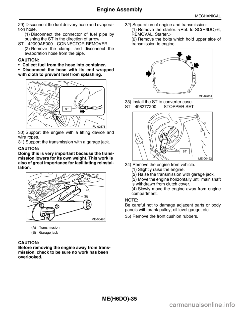
29) Disconnect the fuel delivery hose and evapora-
tion hose.
(1) Disconnect the connector of fuel pipe by
pushing the ST in the direction of arrow.
ST 42099AE000 CONNECTOR REMOVER
(2) Remove the clamp, and disconnect the
evaporation hose from the pipe.
CAUTION:
•Collect fuel from the hose into container.
•Disconnect the hose with its end wrapped
with cloth to prevent fuel from splashing.
30) Support the engine with a lifting device and
wire ropes.
31) Support the transmission with a garage jack.
CAUTION:
Doing this is very important because the trans-
mission lowers for its own weight. This work is
also of great importance for facilitating reinstal-
lation.
CAUTION:
Before removing the engine away from trans-
mission, check to be sure no work has been
overlooked.
32) Separation of engine and transmission:
(1) Remove the starter.
(2) Remove the bolts which hold upper side of
transmission to engine.
33) Install the ST to converter case.
ST 498277200 STOPPER SET
34) Remove the engine from vehicle.
(1) Slightly raise the engine.
(2) Raise the transmission with garage jack.
(3) Move the engine horizontally until main shaft
is withdrawn from clutch cover.
(4) Slowly move the engine away from engine
compartment.
NOTE:
Be careful not to damage adjacent parts or body
panels with crank pulley, oil level gauge, etc.
35) Remove the front cushion rubbers.
(A) Transmission
(B) Garage jack
(A)
(B)
ME-00490
ME-02661
ST
ME-00492
Page 1904 of 2453
ME(H6DO)-38
Engine Assembly
MECHANICAL
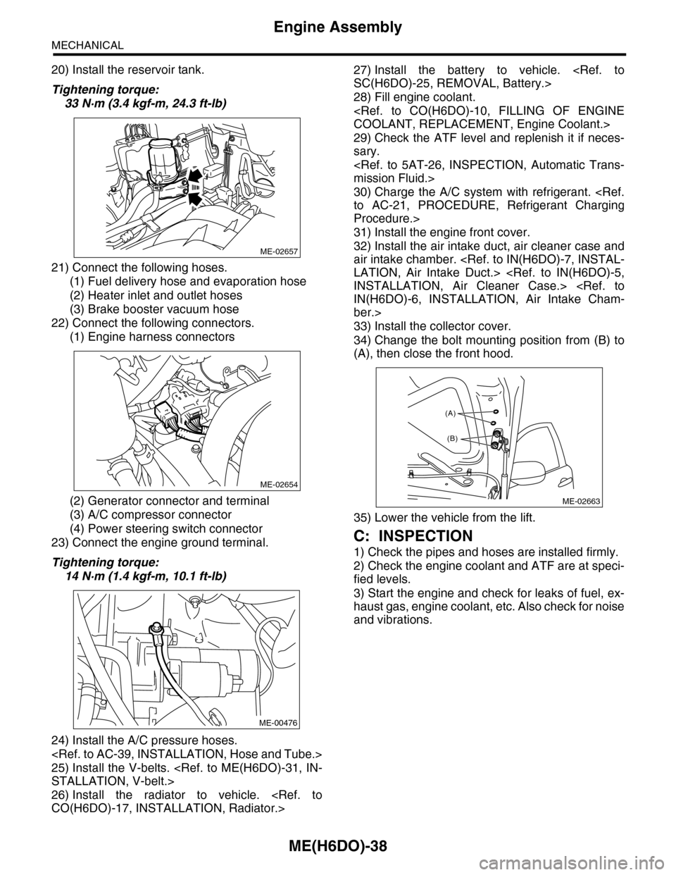
20) Install the reservoir tank.
Tightening torque:
33 N·m (3.4 kgf-m, 24.3 ft-lb)
21) Connect the following hoses.
(1) Fuel delivery hose and evaporation hose
(2) Heater inlet and outlet hoses
(3) Brake booster vacuum hose
22) Connect the following connectors.
(1) Engine harness connectors
(2) Generator connector and terminal
(3) A/C compressor connector
(4) Power steering switch connector
23) Connect the engine ground terminal.
Tightening torque:
14 N·m (1.4 kgf-m, 10.1 ft-lb)
24) Install the A/C pressure hoses.
25) Install the V-belts.
26) Install the radiator to vehicle.
27) Install the battery to vehicle.
28) Fill engine coolant.
29) Check the ATF level and replenish it if neces-
sary.
30) Charge the A/C system with refrigerant.
Procedure.>
31) Install the engine front cover.
32) Install the air intake duct, air cleaner case and
air intake chamber.
ber.>
33) Install the collector cover.
34) Change the bolt mounting position from (B) to
(A), then close the front hood.
35) Lower the vehicle from the lift.
C: INSPECTION
1) Check the pipes and hoses are installed firmly.
2) Check the engine coolant and ATF are at speci-
fied levels.
3) Start the engine and check for leaks of fuel, ex-
haust gas, engine coolant, etc. Also check for noise
and vibrations.
ME-02657
ME-02654
ME-00476
ME-02663
(A)
(B)
Page 1907 of 2453
ME(H6DO)-41
Crank Pulley
MECHANICAL
13.Crank Pulley
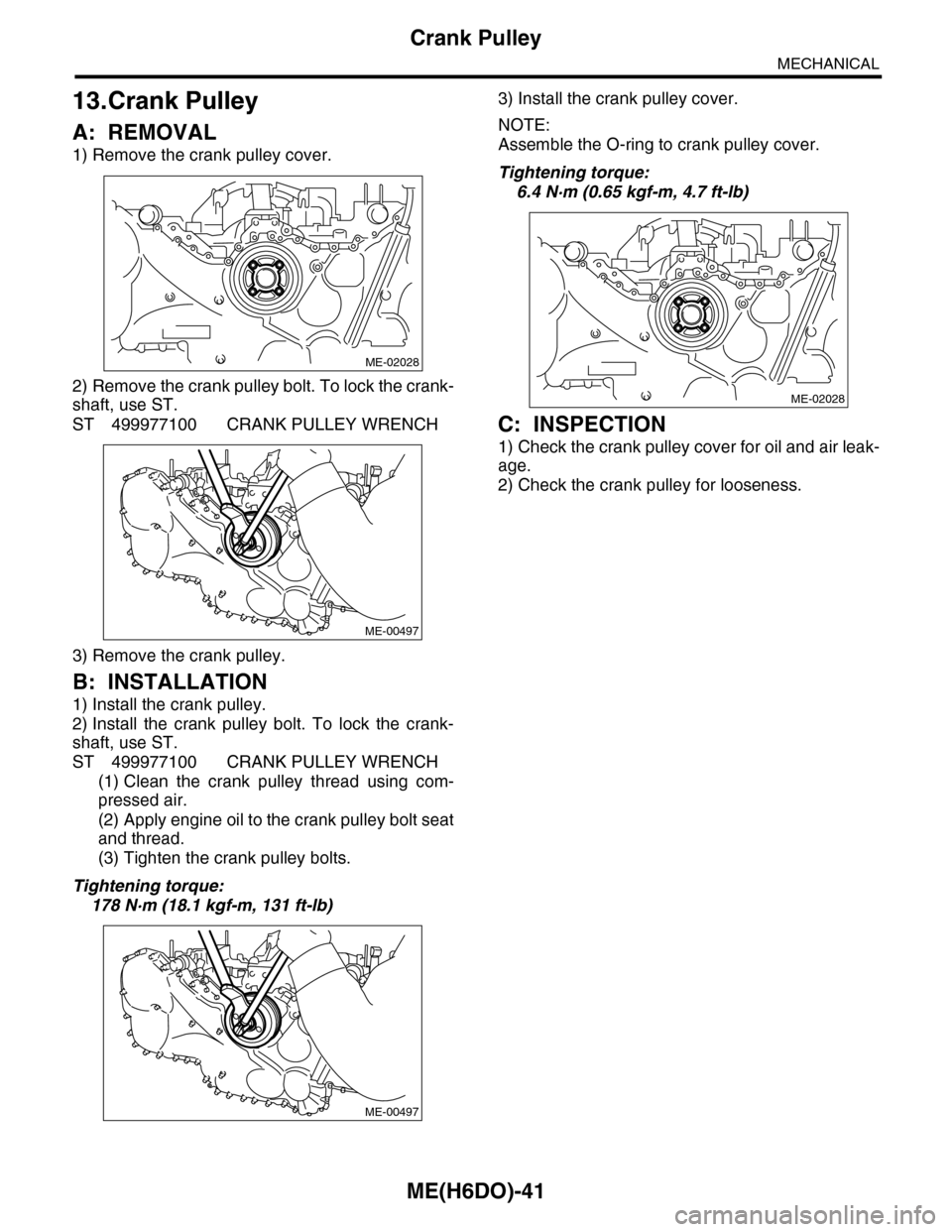
A: REMOVAL
1) Remove the crank pulley cover.
2) Remove the crank pulley bolt. To lock the crank-
shaft, use ST.
ST 499977100 CRANK PULLEY WRENCH
3) Remove the crank pulley.
B: INSTALLATION
1) Install the crank pulley.
2) Install the crank pulley bolt. To lock the crank-
shaft, use ST.
ST 499977100 CRANK PULLEY WRENCH
(1) Clean the crank pulley thread using com-
pressed air.
(2) Apply engine oil to the crank pulley bolt seat
and thread.
(3) Tighten the crank pulley bolts.
Tightening torque:
178 N·m (18.1 kgf-m, 131 ft-lb)
3) Install the crank pulley cover.
NOTE:
Assemble the O-ring to crank pulley cover.
Tightening torque:
6.4 N·m (0.65 kgf-m, 4.7 ft-lb)
C: INSPECTION
1) Check the crank pulley cover for oil and air leak-
age.
2) Check the crank pulley for looseness.
ME-02028
ME-00497
ME-00497
ME-02028
Page 1924 of 2453
ME(H6DO)-58
Cylinder Head
MECHANICAL
8) Install the front chain cover.
9) Install the crank pulley.
C: DISASSEMBLY
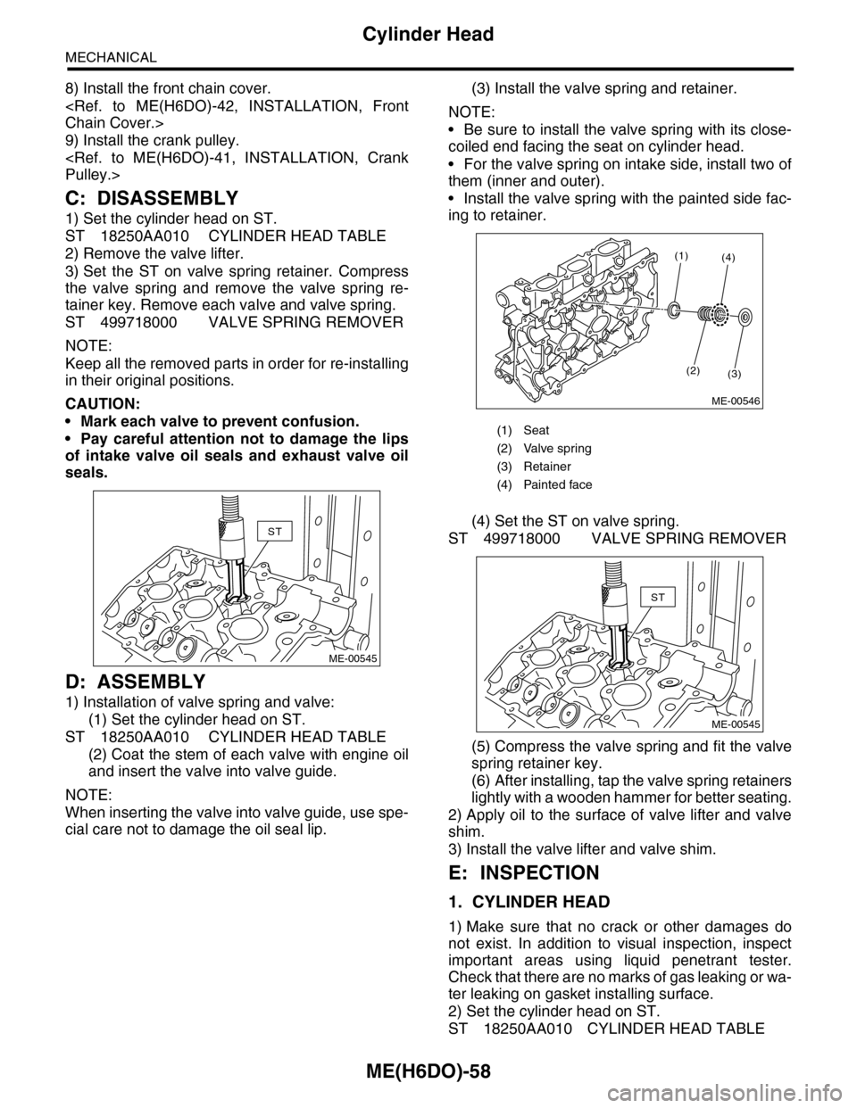
1) Set the cylinder head on ST.
ST 18250AA010 CYLINDER HEAD TABLE
2) Remove the valve lifter.
3) Set the ST on valve spring retainer. Compress
the valve spring and remove the valve spring re-
tainer key. Remove each valve and valve spring.
ST 499718000 VALVE SPRING REMOVER
NOTE:
Keep all the removed parts in order for re-installing
in their original positions.
CAUTION:
•Mark each valve to prevent confusion.
•Pay careful attention not to damage the lips
of intake valve oil seals and exhaust valve oil
seals.
D: ASSEMBLY
1) Installation of valve spring and valve:
(1) Set the cylinder head on ST.
ST 18250AA010 CYLINDER HEAD TABLE
(2) Coat the stem of each valve with engine oil
and insert the valve into valve guide.
NOTE:
When inserting the valve into valve guide, use spe-
cial care not to damage the oil seal lip.
(3) Install the valve spring and retainer.
NOTE:
•Be sure to install the valve spring with its close-
coiled end facing the seat on cylinder head.
•For the valve spring on intake side, install two of
them (inner and outer).
•Install the valve spring with the painted side fac-
ing to retainer.
(4) Set the ST on valve spring.
ST 499718000 VALVE SPRING REMOVER
(5) Compress the valve spring and fit the valve
spring retainer key.
(6) After installing, tap the valve spring retainers
lightly with a wooden hammer for better seating.
2) Apply oil to the surface of valve lifter and valve
shim.
3) Install the valve lifter and valve shim.
E: INSPECTION
1. CYLINDER HEAD
1) Make sure that no crack or other damages do
not exist. In addition to visual inspection, inspect
important areas using liquid penetrant tester.
Check that there are no marks of gas leaking or wa-
ter leaking on gasket installing surface.
2) Set the cylinder head on ST.
ST 18250AA010 CYLINDER HEAD TABLE
ST
ME-00545
(1) Seat
(2) Valve spring
(3) Retainer
(4) Painted face
(1)
(2)(3)
(4)
ME-00546
ST
ME-00545
Page 1926 of 2453
ME(H6DO)-60
Cylinder Head
MECHANICAL
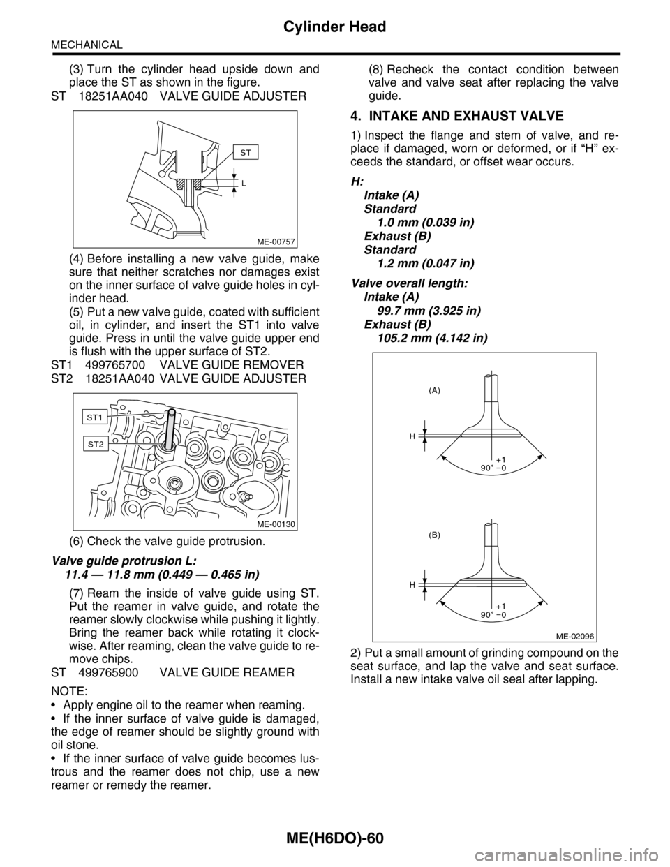
(3) Turn the cylinder head upside down and
place the ST as shown in the figure.
ST 18251AA040 VALVE GUIDE ADJUSTER
(4) Before installing a new valve guide, make
sure that neither scratches nor damages exist
on the inner surface of valve guide holes in cyl-
inder head.
(5) Put a new valve guide, coated with sufficient
oil, in cylinder, and insert the ST1 into valve
guide. Press in until the valve guide upper end
is flush with the upper surface of ST2.
ST1 499765700 VALVE GUIDE REMOVER
ST2 18251AA040 VALVE GUIDE ADJUSTER
(6) Check the valve guide protrusion.
Valve guide protrusion L:
11.4 — 11.8 mm (0.449 — 0.465 in)
(7) Ream the inside of valve guide using ST.
Put the reamer in valve guide, and rotate the
reamer slowly clockwise while pushing it lightly.
Bring the reamer back while rotating it clock-
wise. After reaming, clean the valve guide to re-
move chips.
ST 499765900 VALVE GUIDE REAMER
NOTE:
•Apply engine oil to the reamer when reaming.
•If the inner surface of valve guide is damaged,
the edge of reamer should be slightly ground with
oil stone.
•If the inner surface of valve guide becomes lus-
trous and the reamer does not chip, use a new
reamer or remedy the reamer.
(8) Recheck the contact condition between
valve and valve seat after replacing the valve
guide.
4. INTAKE AND EXHAUST VALVE
1) Inspect the flange and stem of valve, and re-
place if damaged, worn or deformed, or if “H” ex-
ceeds the standard, or offset wear occurs.
H:
Intake (A)
Standard
1.0 mm (0.039 in)
Exhaust (B)
Standard
1.2 mm (0.047 in)
Valve overall length:
Intake (A)
99.7 mm (3.925 in)
Exhaust (B)
105.2 mm (4.142 in)
2) Put a small amount of grinding compound on the
seat surface, and lap the valve and seat surface.
Install a new intake valve oil seal after lapping.
ME-00757
ST
L
ME-00130
ST1
ST2
ME-02096
H
H
(B)
(A)
90 0+1
90 0+1
Page 1927 of 2453
ME(H6DO)-61
Cylinder Head
MECHANICAL
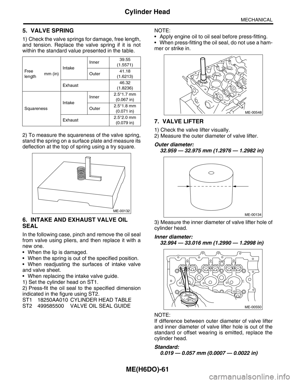
5. VALVE SPRING
1) Check the valve springs for damage, free length,
and tension. Replace the valve spring if it is not
within the standard value presented in the table.
2) To measure the squareness of the valve spring,
stand the spring on a surface plate and measure its
deflection at the top of spring using a try square.
6. INTAKE AND EXHAUST VALVE OIL
SEAL
In the following case, pinch and remove the oil seal
from valve using pliers, and then replace it with a
new one.
•When the lip is damaged.
•When the spring is out of the specified position.
•When readjusting the surfaces of intake valve
and valve sheet.
•When replacing the intake valve guide.
1) Set the cylinder head on ST1.
2) Press-fit the oil seal to the specified dimension
indicated in the figure using ST2.
ST1 18250AA010 CYLINDER HEAD TABLE
ST2 499585500 VALVE OIL SEAL GUIDE
NOTE:
•Apply engine oil to oil seal before press-fitting.
•When press-fitting the oil seal, do not use a ham-
mer or strike in.
7. VALVE LIFTER
1) Check the valve lifter visually.
2) Measure the outer diameter of valve lifter.
Outer diameter:
32.959 — 32.975 mm (1.2976 — 1.2982 in)
3) Measure the inner diameter of valve lifter hole of
cylinder head.
Inner diameter:
32.994 — 33.016 mm (1.2990 — 1.2998 in)
NOTE:
If difference between outer diameter of valve lifter
and inner diameter of valve lifter hole is out of the
standard or offset wearing is emitted, replace the
cylinder head.
Standard:
0.019 — 0.057 mm (0.0007 — 0.0022 in)
Fr e e
lengthmm (in)
Intake
Inner39.55
(1.5571)
Outer41.18
(1.6213)
Exhaust46.32
(1.8236)
Squareness
Intake
Inner2.5°1.7 mm
(0.067 in)
Outer2.5°1.8 mm
(0.071 in)
Exhaust2.5°2.0 mm
(0.079 in)
ME-00132
ME-00548
ME-00134
ME-00550