Page 197 of 2453

ET-11
Control Panel
ENTERTAINMENT
C: INSPECTION
NOTE:
•For self diagnosis of the audio system, there is a communications check (communication condition be-
tween the audio and the control panel) and a switch check. Perform a communications check first and make
sure it is operating normally before proceeding to the inspection of switches.
•Complete operations from when the self diagnosis mode of step 1 operates and the buzzer sounds, to
pressing the preset 1 switch in 3., within 15 seconds. If more than 15 seconds pass, a communications error
will be displayed.
•During the diagnosis, do not press the POWER(8), FM(12), AM(14), CD(11), RSE AUX(13) switches.
Pressing these switches will disengage the self diagnosis mode.
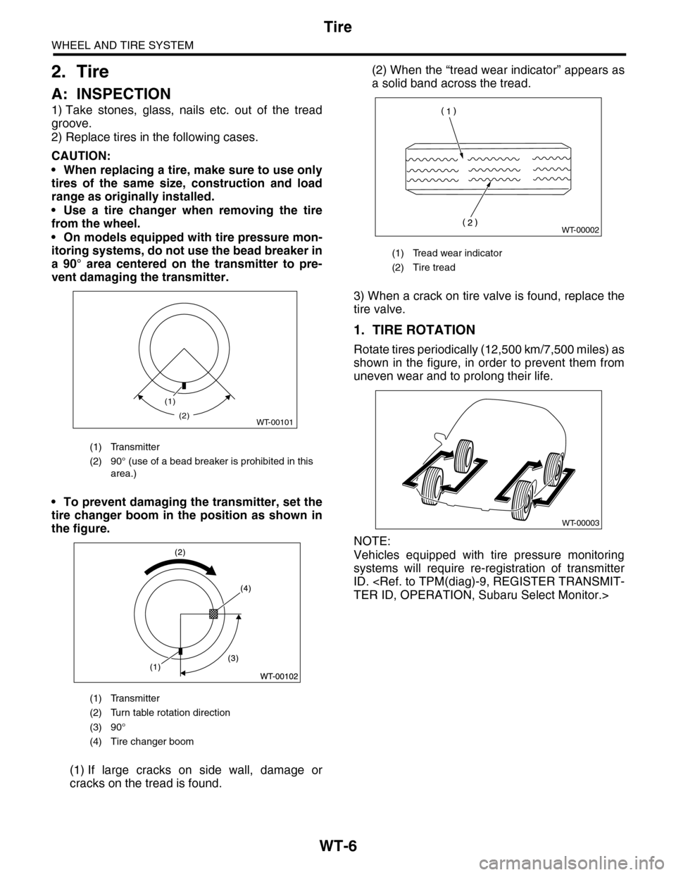
(1) SEEK UP switch (7) SCAN switch (13) RSE AUX switch
(2) SEEK DOWN switch (8) PUSH/POWER switch (14) AM switch
(3) TUNE TRACK UP switch (9) VOLUME (15) TONE/BAL switch
(4) TUNE TRACK DOWN switch (10) Presets 1 — 6 (16) LOAD switch
(5) RPT switch (11) CD switch (17) EJECT switch
(6) RDM switch (12) FM switch (18) TEMP display section
FMTUNETUNETRATRACKCKSEEKFLDRRPT
SCAN
TONE
BAL RDM
SEEKFLDR
TUNETUNETRATRACKCK
AM
CDCD
RSEAUX
LOAD
MP3
FRONTREARREAR
1
2345
6
6CD CHANGER P-1366CD CHANGER P-136
PMETPMET
LOV
PUSH PO POWERWER
(12)
(11)(3)
(9)
(2)(10)(10)
(16)
(18)(18)
(17)
(1)
(15)
(6)
(7)
(5)
(8)(4)
(14)
(13)
ET-00198
Page 1112 of 2453

WT-6
Tire
WHEEL AND TIRE SYSTEM
2. Tire
A: INSPECTION
1) Take stones, glass, nails etc. out of the tread
groove.
2) Replace tires in the following cases.
CAUTION:
•When replacing a tire, make sure to use only
tires of the same size, construction and load
range as originally installed.
•Use a tire changer when removing the tire
from the wheel.
•On models equipped with tire pressure mon-
itoring systems, do not use the bead breaker in
a 90° area centered on the transmitter to pre-
vent damaging the transmitter.
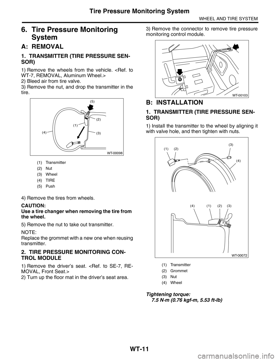
•To prevent damaging the transmitter, set the
tire changer boom in the position as shown in
the figure.
(1) If large cracks on side wall, damage or
cracks on the tread is found.
(2) When the “tread wear indicator” appears as
a solid band across the tread.
3) When a crack on tire valve is found, replace the
tire valve.
1. TIRE ROTATION
Rotate tires periodically (12,500 km/7,500 miles) as
shown in the figure, in order to prevent them from
uneven wear and to prolong their life.
NOTE:
Vehicles equipped with tire pressure monitoring
systems will require re-registration of transmitter
ID.
TER ID, OPERATION, Subaru Select Monitor.>
(1) Transmitter
(2) 90° (use of a bead breaker is prohibited in this
area.)
(1) Transmitter
(2) Turn table rotation direction
(3) 90°
(4) Tire changer boom
(1)
WT-00101(2)
(1) Tread wear indicator
(2) Tire tread
WT-00002
WT-00003
Page 1117 of 2453

WT-11
Tire Pressure Monitoring System
WHEEL AND TIRE SYSTEM
6. Tire Pressure Monitoring
System
A: REMOVAL
1. TRANSMITTER (TIRE PRESSURE SEN-
SOR)
1) Remove the wheels from the vehicle.
WT-7, REMOVAL, Aluminum Wheel.>
2) Bleed air from tire valve.
3) Remove the nut, and drop the transmitter in the
tire.
4) Remove the tires from wheels.
CAUTION:
Use a tire changer when removing the tire from
the wheel.
5) Remove the nut to take out transmitter.
NOTE:
Replace the grommet with a new one when reusing
transmitter.
2. TIRE PRESSURE MONITORING CON-
TROL MODULE
1) Remove the driver’s seat.
MOVAL, Front Seat.>
2) Turn up the floor mat in the driver’s seat area.
3) Remove the connector to remove tire pressure
monitoring control module.
B: INSTALLATION
1. TRANSMITTER (TIRE PRESSURE SEN-
SOR)
1) Install the transmitter to the wheel by aligning it
with valve hole, and then tighten with nuts.
Tightening torque:
7.5 N·m (0.76 kgf-m, 5.53 ft-lb)
(1) Transmitter
(2) Nut
(3) Wheel
(4) TIRE
(5) Push
(1)
(4)
(5)
(2)
WT-00098
(3)
(1) Transmitter
(2) Grommet
(3) Nut
(4) Wheel
WT-00103
WT-00072
(2)(3)
(4)
(1)
(3)(2)(1)(4)
Page 1118 of 2453
WT-12
Tire Pressure Monitoring System
WHEEL AND TIRE SYSTEM
2) Install the tires to wheels.
CAUTION:
•Use a tire changer when installing tire to
wheel.
•To prevent damaging the transmitter, set the
tire changer boom in the position as shown in
the figure.
3) Install the wheels to vehicle.
STALLATION, Aluminum Wheel.>
4) Register the transmitter ID to the tire pressure
monitoring control module.
REGISTER TRANSMITTER ID, OPERATION,
Subaru Select Monitor.>
2. TIRE PRESSURE MONITORING CON-
TROL MODULE
Install in the reverse order of removal.
Tightening torque:
8 N·m (0.8 kgf-m, 5.8 ft-lb)
C: ADJUSTMENT
Re-register the transmitter ID when transmitter has
been replaced or tires have been rotated.
TPM(diag)-9, REGISTER TRANSMITTER ID, OP-
ERATION, Subaru Select Monitor.>
(1) Transmitter
(2) Turn table rotation direction
(3) 90°
(4) Tire changer boom