Page 933 of 2453

PS-53
General Diagnostic Table
POWER ASSISTED SYSTEM (POWER STEERING)
3. INSPECTION OF CLEARANCE
This table lists various clearances that must be correctly adjusted to ensure the normal vehicle driving with-
out interfering noise, or any other faults.
Install locations Minimum allowance mm (in)
(1) Crossmember-to-Hose assembly 10 (0.39)
(2) Front frame side-to-Hose assembly 15 (0.59)
(3) Air bag sensor to cooler pipe assembly 10 (0.39)
(4) Air cleaner case-to-Suction hose 10 (0.39)
(5) VDCH/U to Reservoir tank bracket 10 (0.39)
(6) Air boots to Hose clip15 (0.59)
(7) Air boot-to-Hose assembly15 (0.59)
(8) Protector to Hose assembly10 (0.39)
(9) Intake manifold to Suction hose 10 (0.39)
(10) Intake manifold to hose assembly 10 (0.39)
(11) Air cleaner case to Cooler pipe joint block 5 (0.20)
(12) Chain cover to Cooler pipe joint block 20 (0.79)
(13) Oil pipe to Cooler pipe joint block 20 (0.79)
(14) Suction hose to Hose assembly 10 (0.39)
(15) Air boot to Reservoir tank10 (0.39)
(16) Brake pipe to Reservoir tank10 (0.39)
(17) Harness to Hose assembly10 (0.39)
(18) Relay box to Hose assembly15 (0.59)
(19) Bumper beam to Cooler pipe assembly 10 (0.39)
(20) Radiator bracket to Cooler pipe assembly 10 (0.39)
(21) ATF cooler to Cooler pipe assembly 10 (0.39)
(22) Undercover to cooler pipe assembly 10 (0.39)
(23) Protector to Hose assembly10 (0.39)
(24) Protector to Hose assembly15 (0.59)
(25) Return hose to Hose assembly 10 (0.39)
(26) Air cleaner case to Hose assembly 10 (0.39)
(27) Suction hose to Hose assembly 10 (0.39)
(28) Air cleaner case to Return hose 3 (0.12)
(29) Valve housing to DOJ12 (0.47)
(30) Valve housing to Crossmember 1 (0.04)
(31) Mount to Crossmember There must be no contact.
(32) Feed tube to Crossmember3 (0.12)
(33) Elbow to Crossmember3 (0.12)
(34) Cylinder pipe to Crossmember 3 (0.12)
(35) Feed tube to Exhaust pipe18 (0.71)
(36) Tie-rod end to Brake dust cover 2.5 (0.10)
(37) Coupling rubber to AT level gage 10 (0.39)
(38) Yoke to Brake booster5 (0.20)
Page 1132 of 2453

CO(H6DO)-13
Water Pump
COOLING
4. Water Pump
A: REMOVAL
1) Remove the radiator.
REMOVAL, Radiator.>
2) Remove the V-belts.
3) Remove the front chain cover.
Cover.>
4) Remove the timing chain assembly.
Assembly.>
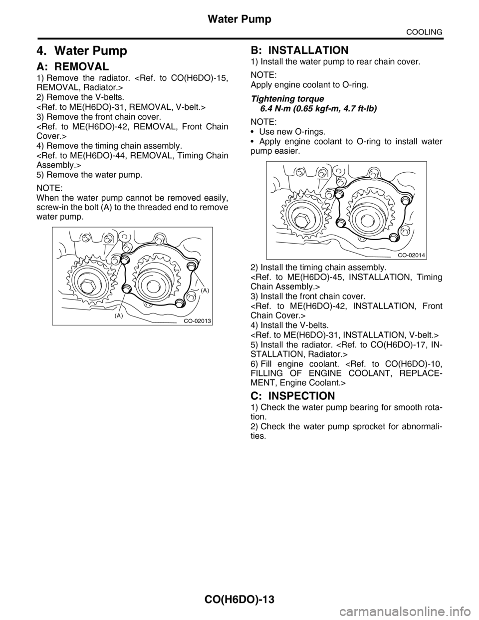
5) Remove the water pump.
NOTE:
When the water pump cannot be removed easily,
screw-in the bolt (A) to the threaded end to remove
water pump.
B: INSTALLATION
1) Install the water pump to rear chain cover.
NOTE:
Apply engine coolant to O-ring.
Tightening torque
6.4 N·m (0.65 kgf-m, 4.7 ft-lb)
NOTE:
•Use new O-rings.
•Apply engine coolant to O-ring to install water
pump easier.
2) Install the timing chain assembly.
Chain Assembly.>
3) Install the front chain cover.
Chain Cover.>
4) Install the V-belts.
5) Install the radiator.
STALLATION, Radiator.>
6) Fill engine coolant.
FILLING OF ENGINE COOLANT, REPLACE-
MENT, Engine Coolant.>
C: INSPECTION
1) Check the water pump bearing for smooth rota-
tion.
2) Check the water pump sprocket for abnormali-
ties.
CO-02013
(A)
(A)
CO-02014
Page 1857 of 2453

LU(H6DO)-8
Oil Pump
LUBRICATION
4. Oil Pump
A: REMOVAL
1) Remove the collector cover.
2) Disconnect the ground cable from battery.
3) Lift-up the vehicle.
4) Remove the under cover.
5) Drain engine coolant.
DRAINING OF ENGINE COOLANT, REPLACE-
MENT, Engine Coolant.>
6) Lower the vehicle.
7) Remove the radiator.
REMOVAL, Radiator.>
8) Remove the V-belts.
REMOVAL, V-belt.>
9) Remove the front chain cover.
ME(H6DO)-42, REMOVAL, Front Chain Cover.>
10) Remove the timing chain.
44, REMOVAL, Timing Chain Assembly.>
11) Remove the crank sprocket.
12) Remove the oil pump cover.
13) Remove the inner rotor and outer rotor.
B: INSTALLATION
1) Apply a coat of engine oil to the whole area of in-
ner rotor and outer rotor.
2) Set the inner rotor onto opening edge of crank
shaft, and install the inner rotor, and then assemble
the outer rotor.
3) Install the oil pump cover.
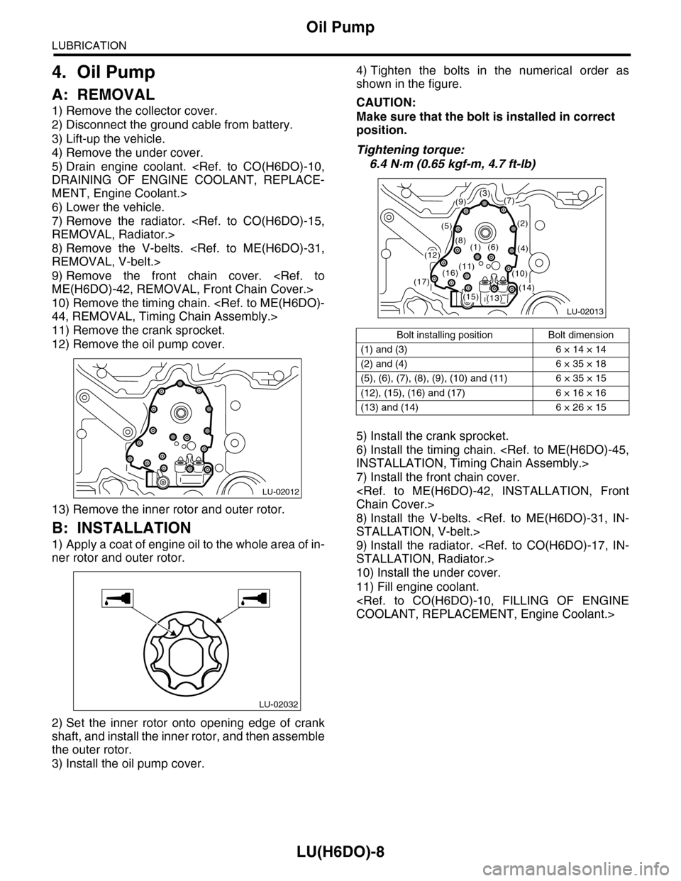
4) Tighten the bolts in the numerical order as
shown in the figure.
CAUTION:
Make sure that the bolt is installed in correct
position.
Tightening torque:
6.4 N·m (0.65 kgf-m, 4.7 ft-lb)
5) Install the crank sprocket.
6) Install the timing chain.
INSTALLATION, Timing Chain Assembly.>
7) Install the front chain cover.
Chain Cover.>
8) Install the V-belts.
STALLATION, V-belt.>
9) Install the radiator.
STALLATION, Radiator.>
10) Install the under cover.
11) Fill engine coolant.
COOLANT, REPLACEMENT, Engine Coolant.>
LU-02012
LU-02032
Bolt installing position Bolt dimension
(1) and (3) 6 × 14 × 14
(2) and (4) 6 × 35 × 18
(5), (6), (7), (8), (9), (10) and (11) 6 × 35 × 15
(12), (15), (16) and (17) 6 × 16 × 16
(13) and (14) 6 × 26 × 15
LU-02013
(3)(7)
(2)
(4)
(9)
(5)
(8)(1)(6)(12)
(13)(14)(15)
(16)(17)
(11)(10)
Page 1872 of 2453
ME(H6DO)-6
General Description
MECHANICAL
2. TIMING CHAIN COVER
(1) Crank pulley coverTightening torque: N·m (kgf-m, ft-lb)
(2) O-ringT1:
Pulley.>(3) Crank pulley
(4) Sealing washerT2:
Chain Cover.>(5) Oil seal
(6) Front chain cover T3:
Chain Cover.>(7) Rear chain cover
(8) Water pump gasket T4: 6.4 (0.65, 4.7)
ME-02021
T2
T2
T2
T2
T3T3
T3
T3
T3
(4)
(6)
(7)
(8)
(5)
T1
T4
(1)
(3)
(2)
Page 1875 of 2453

ME(H6DO)-9
General Description
MECHANICAL
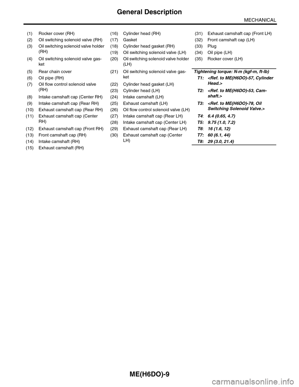
(1) Rocker cover (RH) (16) Cylinder head (RH) (31) Exhaust camshaft cap (Front LH)
(2) Oil switching solenoid valve (RH) (17) Gasket (32) Front camshaft cap (LH)
(3) Oil switching solenoid valve holder
(RH)
(18) Cylinder head gasket (RH) (33) Plug
(19) Oil switching solenoid valve (LH) (34) Oil pipe (LH)
(4) Oil switching solenoid valve gas-
ket
(20) Oil switching solenoid valve holder
(LH)
(35) Rocker cover (LH)
(5) Rear chain cover (21) Oil switching solenoid valve gas-
ket
Tightening torque: N·m (kgf-m, ft-lb)
(6) Oil pipe (RH)T1:
Head.>(7) Oil flow control solenoid valve
(RH)
(22) Cylinder head gasket (LH)
(23) Cylinder head (LH)T2:
shaft.>(8) Intake camshaft cap (Center RH) (24) Intake camshaft (LH)
(9) Intake camshaft cap (Rear RH) (25) Exhaust camshaft (LH)T3:
Switching Solenoid Valve.>(10) Exhaust camshaft cap (Rear RH) (26) Oil flow control solenoid valve (LH)
(11) Exhaust camshaft cap (Center
RH)
(27) Intake camshaft cap (Rear LH)T4:6.4 (0.65, 4.7)
(28) Intake camshaft cap (Center LH)T5: 9.75 (1.0, 7.2)
(12) Exhaust camshaft cap (Front RH) (29) Exhaust camshaft cap (Rear LH)T6:16 (1.6, 12)
(13) Front camshaft cap (RH) (30) Exhaust camshaft cap (Center
LH)
T7: 60 (6.1, 44)
(14) Intake camshaft (RH)T8: 29 (3.0, 21.4)
(15) Exhaust camshaft (RH)
Page 1880 of 2453

ME(H6DO)-14
General Description
MECHANICAL
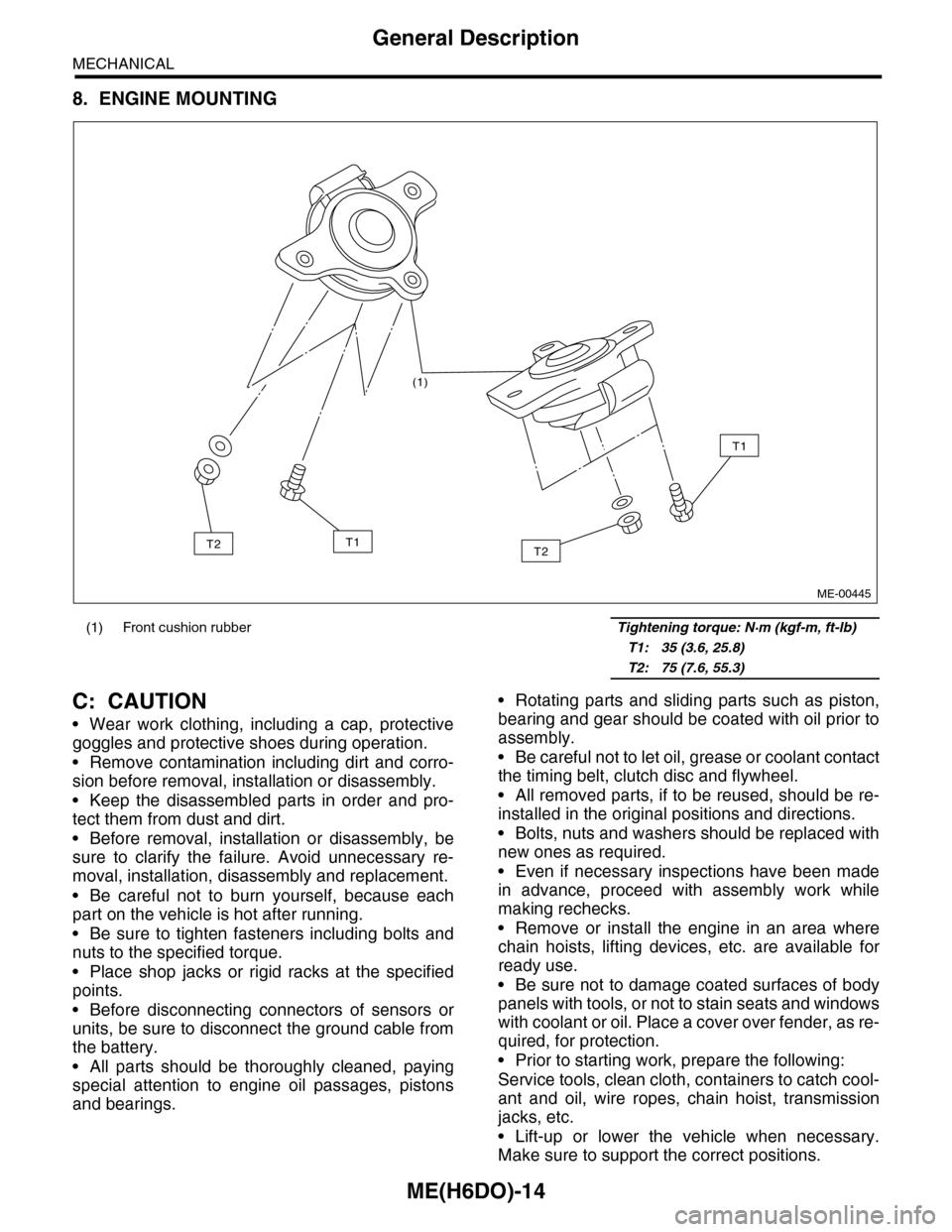
8. ENGINE MOUNTING
C: CAUTION
•Wear work clothing, including a cap, protective
goggles and protective shoes during operation.
•Remove contamination including dirt and corro-
sion before removal, installation or disassembly.
•Keep the disassembled parts in order and pro-
tect them from dust and dirt.
•Before removal, installation or disassembly, be
sure to clarify the failure. Avoid unnecessary re-
moval, installation, disassembly and replacement.
•Be careful not to burn yourself, because each
part on the vehicle is hot after running.
•Be sure to tighten fasteners including bolts and
nuts to the specified torque.
•Place shop jacks or rigid racks at the specified
points.
•Before disconnecting connectors of sensors or
units, be sure to disconnect the ground cable from
the battery.
•All parts should be thoroughly cleaned, paying
special attention to engine oil passages, pistons
and bearings.
•Rotating parts and sliding parts such as piston,
bearing and gear should be coated with oil prior to
assembly.
•Be careful not to let oil, grease or coolant contact
the timing belt, clutch disc and flywheel.
•All removed parts, if to be reused, should be re-
installed in the original positions and directions.
•Bolts, nuts and washers should be replaced with
new ones as required.
•Even if necessary inspections have been made
in advance, proceed with assembly work while
making rechecks.
•Remove or install the engine in an area where
chain hoists, lifting devices, etc. are available for
ready use.
•Be sure not to damage coated surfaces of body
panels with tools, or not to stain seats and windows
with coolant or oil. Place a cover over fender, as re-
quired, for protection.
•Prior to starting work, prepare the following:
Service tools, clean cloth, containers to catch cool-
ant and oil, wire ropes, chain hoist, transmission
jacks, etc.
•Lift-up or lower the vehicle when necessary.
Make sure to support the correct positions.
(1) Front cushion rubber Tightening torque: N·m (kgf-m, ft-lb)
T1: 35 (3.6, 25.8)
T2: 75 (7.6, 55.3)
(1)
T2
T1
T1T2
ME-00445
Page 1908 of 2453
ME(H6DO)-42
Front Chain Cover
MECHANICAL
14.Front Chain Cover
A: REMOVAL
1) Remove the crank pulley.
41, REMOVAL, Crank Pulley.>
2) Remove the front chain cover.
NOTE:
Chain cover installation bolt has three different siz-
es. To prevent the confusion in installation, keep
these bolts on container individually.
B: INSTALLATION
1) Remove the used liquid gasket from mating sur-
face, and degrease it.
2) Apply liquid gasket to the mating surface of front
chain cover.
Liquid gasket
THREE BOND 1280B (Part No. K0877YA018)
Applying liquid gasket diameter
2.5±0.5 mm (0.098±0.020 in)
3) Install the front chain cover. Temporarily tighten
the bolts.
CAUTION:
Do not install the bolts in wrong place.
(A) M6 × 16
(B) M6 × 30
(C) M6 × 45
*: Sealing washer
(C)
(C)
(A)
(B)
(B)
ME-02029
(A)
(A) M6 × 16
(B) M6 × 30
(C) M6 × 45
*: Sealing washer
ME-02385
(C)
(C)
(A)
(B)
(B)
ME-02029
(A)
Page 1909 of 2453
ME(H6DO)-43
Front Chain Cover
MECHANICAL
4) Tighten the bolts in the numerical order as shown in the figure.
Tightening torque:
6.6 N·m (0.67 kgf-m, 4.8 ft-lb)
5) Install the crank pulley.
C: INSPECTION
Check the cover surface for scratch and damage.
Check for oil leakage on cover mating surface and installation part of crank pulley.
ME-02031
(21)
(22)(40)(39)
(38)
(37)
(36)
(35)
(34)
(33)
(32)(13)(12)(11)
(9)(10)
(23)(24)
(8)
(6)
(25)
(26)
(27)
(28)
(29)(30) (31)(19)
(18)
(17)(16) (15)(14)(20)
(3)
(2)
(4)(5)
(1)
(7)