2009 SUBARU TRIBECA dimensions
[x] Cancel search: dimensionsPage 328 of 2453

AC-2
General Description
HVAC SYSTEM (HEATER, VENTILATOR AND A/C)
1. General Description
A: SPECIFICATION
1. HEATER SYSTEM
2. A/C SYSTEM
•Single A/C model (front only)
Item Specification Condition
Heating capacity5.2 kW (4,471 kcal/h, 17,743
BTU/h) or more
•Mode selector switch: HEAT
•Temperature control switch: FULL HOT
•Temperature difference between hot water and inlet
air: 65°C (149°F)
•Hot water flow rate: 360 2 (95.1 US gal, 79.2 Imp
gal)/h
Air flow rate340 m3 (11,301 cu ft)/hHeat mode (FRESH), FULL HOT at 12.5 V
Max air flow rate550 m3 (16,245 cu ft)/h
•Temperature control switch: FULL COLD
•Blower fan speed:
6th position
•Mode selector lever: RECIRC
Heater core size
(height × length × width)
264 × 110 × 27 mm
(10.4 × 4.33 × 1.06 in)—
Blower Motor
Ty p e B r u s h m o t o r 2 2 0 W o r l e s s 1 2 V
Fa n t y pe an d si ze
(diameter × width)
Sirocco fan type
165 ×75 mm (6.51 × 2.95 in)—
Item Specification
Ty p e o f a i r c o n d i t i o n e r R e h e a t a i r - m i x t y p e
Cooling capacity6.2 kW
(5,331 kcal/h, 21,154 BTU/h)
RefrigerantHFC-134a (CH2FCF3)
[0.87±0.03 kg (1.92±0.07 lb)]
Compressor
Ty p eInclined plate (SWASH PLATE), fixed capacity
(10SR17), Temperature fuse
Exhaust 177 cc (10.80 cu in)/rev
Max. permissible speed 6,000 rpm
Magnet clutch
Ty p e D r y, s i n g l e - d i s c t y p e
Powe r c on su mp t i on 35 W
Ty p e o f b e l t V- b e l t 6 P K
Pulley dia. (effective dia.) 115 mm (4.53 in)
Pulley ratio 1.16
Condenser
Ty p e C o r r u g a t e d f i n ( S u b c o o l t y p e )
Core face area0.29 m2 (3.122 sq ft)
Core thickness 16 mm (0.63 in)
Radiation area7.65 m2 (82.35 sq ft)
Receiver drier Effective inner capacity190 cm3 (11.6 cu in)
Expansion valve Type Box time (external pressure equalizing type)
Evaporator
Ty p e S i n g l e t a n k
Dimensions (W × H × T)293.1 × 211 × 38 mm
(11.54 × 8.31 × 1.50 in)
Blower fan
Fan t yp e S i r oc co fa n
Outer diameter× width 165 ×75 mm (6.50 × 2.95 in)
Powe r c on su mp t i on 2 60 W
Page 330 of 2453

AC-4
General Description
HVAC SYSTEM (HEATER, VENTILATOR AND A/C)
•Dual A/C model (Front A/C and Rear cooler)
Item Specification
Ty p e o f a i r c o n d i t i o n e rFr o nt Reh e at a ir - mi x t y pe
Rear Cooler
Cooling capacity7.2 kW
(5,331 kcal/h, 21,154 BTU/h)
RefrigerantHFC-134a (CH2FCF3)
[0.87±0.03 kg (1.92±0.07 lb)]
Compressor
Ty p eInclined plate (SWASH PLATE), fixed capacity
(10SR17), Temperature fuse
Exhaust 177 cc (10.80 cu in)/rev
Max. permissible speed 6,000 rpm
Magnet clutch
Ty p e D r y, s i n g l e - d i s c t y p e
Powe r c on su mp t i on 35 W
Ty p e o f b e l t V- b e l t 6 P K
Pulley dia. (effective dia.) 115 mm (3.7 in)
Pulley ratio 1.16
Condenser
Ty p e C o r r u g a t e d f i n ( S u b c o o l t y p e )
Core face area0.29 m2 (2.077 sq ft)
Core thickness 16 mm (0.63 in)
Radiation area7.65 m2 (61.57 sq ft)
Receiver drier Effective inner capacity 280 cc (17.1 cu in)
Expansion valveFront TypeBox time (external pressure equalizing type)Rear Type
Evaporator
Front Type Single tank
Dimensions (W × H × T)293.1 × 211 × 38 mm
(11.54 × 8.31× 1.50 in)
Rear
Ty p e S i n g l e t a n k
Dimensions (W × H × T)132.1 × 181 × 38 mm
(5.2 × 7.13× 1.50 in)
Blower fan
Front Fan type Sirocco fan
Outer diameter× width 165 ×75 mm (6.49 × 2.95 in)
Powe r c on su mp t i on 2 60 W
Rear
Fan t yp e S i r oc co fa n
Outer diameter× width 150 ×70 mm (5.91 × 2.95 in)
Powe r c on su mp t i on 1 5 0 W or l es s
Condenser fan (Sub fan)
Motor type Magnet
Powe r c on su mp t i on 1 60 W
Fan o ut e r d i am et e r 3 20 mm (1 2 . 6 i n)
Radiator fan (Main fan)
Motor type Magnet
Powe r c on su mp t i on 1 60 W
Fan o ut e r d i am et e r 3 20 mm (1 2 . 6 i n)
Idling speed (A/C ON) MPFI model 800±100 rpm
Page 716 of 2453

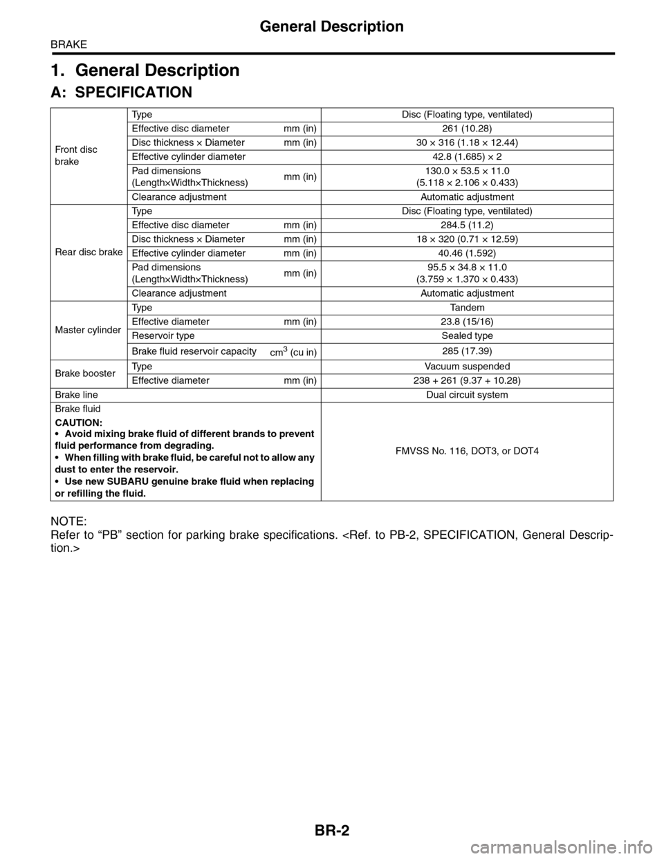
BR-2
General Description
BRAKE
1. General Description
A: SPECIFICATION
NOTE:
Refer to “PB” section for parking brake specifications.
Fr o nt d is c
brake
Ty p e D i s c ( F l o a t i n g t y p e , v e n t i l a t e d )
Effective disc diameter mm (in) 261 (10.28)
Disc thickness × Diameter mm (in) 30 × 316 (1.18 × 12.44)
Effective cylinder diameter 42.8 (1.685) × 2
Pad dimensions
(Length×Width×Thickness)mm (in)130.0 × 53.5 × 11.0
(5.118 × 2.106 × 0.433)
Clearance adjustment Automatic adjustment
Rear disc brake
Ty p e D i s c ( F l o a t i n g t y p e , v e n t i l a t e d )
Effective disc diameter mm (in) 284.5 (11.2)
Disc thickness × Diameter mm (in) 18 × 320 (0.71 × 12.59)
Effective cylinder diameter mm (in) 40.46 (1.592)
Pad dimensions
(Length×Width×Thickness)mm (in)95.5 × 34.8 × 11.0
(3.759 × 1.370 × 0.433)
Clearance adjustment Automatic adjustment
Master cylinder
Ty p e Ta n d e m
Effective diameter mm (in) 23.8 (15/16)
Reservoir type Sealed type
Brake fluid reservoir capacitycm3 (cu in)285 (17.39)
Brake boosterTy p e V a c u u m s u s p e n d e d
Effective diameter mm (in) 238 + 261 (9.37 + 10.28)
Brake lineDual circuit system
Brake fluid
CAUTION:
•Avoid mixing brake fluid of different brands to prevent
fluid performance from degrading.
•When filling with brake fluid, be careful not to allow any
dust to enter the reservoir.
•Use new SUBARU genuine brake fluid when replacing
or refilling the fluid.
FMVSS No. 116, DOT3, or DOT4
Page 873 of 2453

PB-2
General Description
PARKING BRAKE
1. General Description
A: SPECIFICATION
B: COMPONENT
1. PARKING BRAKE (REAR DISC BRAKE)
Ty p e M e c h a n i c a l , d r u m i n d i s c r e a r b r a k e s
Effective drum diameter mm (in) 210 (8.27)
Lining dimensions
(Length×Width×Thickness)mm (in)238.2 × 30.0 × 4.0
(9.378 × 1.181 × 0.157)
Clearance adjustment Manual adjustment
Pe da l s t ro ke n o tc he s /N ( k gf, lb ) 5 — 6 / 3 00 ( 30 . 6, 6 7)
(1) Back plate (8) Strut (15) Shoe hold pin
(2) Retainer (9) Primary return spring (16) Self locking nut (with WAX)
(3) Spring washer (10) Secondary return spring
(4) Lever (11) Adjusting springTightening torque: N·m (kgf-m, ft-lb)
(5) Parking brake shoe (Primary) (12) AdjusterT1: 8 (0.8, 5.9)
(6) Parking brake shoe (Secondary) (13) Brake shoe cupT2: 75 (7.6, 55.33)
(7) Strut spring (14) Brake shoe spring
PB-00083
(5)
(14)
(13)
(12)(9)
(11)
(10)
(8)
(7)
(6)
(4)(3)(2)
(1)
(15)
(16)
T1
T2
Page 1121 of 2453

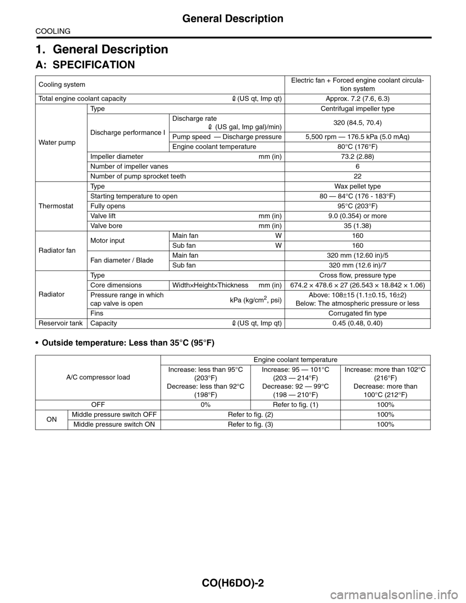
CO(H6DO)-2
General Description
COOLING
1. General Description
A: SPECIFICATION
•Outside temperature: Less than 35°C (95°F)
Cooling systemElectric fan + Forced engine coolant circula-
tion system
To t a l e n g i n e c o o l a n t c a p a c i t y2(US qt, Imp qt) Approx. 7.2 (7.6, 6.3)
Wa t er p u mp
Ty p e C e n t r i f u g a l i m p e l l e r t y p e
Discharge performance I
Discharge rate
2 (US gal, Imp gal)/min)320 (84.5, 70.4)
Pump speed — Discharge pressure 5,500 rpm — 176.5 kPa (5.0 mAq)
Engine coolant temperature 80°C (176°F)
Impeller diameter mm (in) 73.2 (2.88)
Number of impeller vanes 6
Number of pump sprocket teeth 22
Thermostat
Ty p eWa x p el l et t yp e
Starting temperature to open 80 — 84°C (176 - 183°F)
Fully opens 95°C (203°F)
Va l ve l i f t m m ( i n ) 9 . 0 ( 0 . 3 5 4 ) o r m o r e
Va l ve b o r e m m ( i n ) 3 5 ( 1 . 3 8 )
Radiator fan
Motor inputMain fan W 160
Sub fan W 160
Fan di a me t er / B la deMain fan 320 mm (12.60 in)/5
Sub fan 320 mm (12.6 in)/7
Radiator
Ty p e C r o s s f l o w , p r e s s u r e t y p e
Core dimensions Width×Height×Thickness mm (in) 674.2 × 478.6 × 27 (26.543 × 18.842 × 1.06)
Pressure range in which
cap valve is openkPa (kg/cm2, psi)Above: 108±15 (1.1±0.15, 16±2)
Below: The atmospheric pressure or less
FinsCorrugated fin type
Reservoir tank Capacity2(US qt, Imp qt) 0.45 (0.48, 0.40)
A/C compressor load
Engine coolant temperature
Increase: less than 95°C
(203°F)
Decrease: less than 92°C
(198°F)
Increase: 95 — 101°C
(203 — 214°F)
Decrease: 92 — 99°C
(198 — 210°F)
Increase: more than 102°C
(216°F)
Decrease: more than
100°C (212°F)
OFF 0% Refer to fig. (1) 100%
ONMiddle pressure switch OFF Refer to fig. (2) 100%
Middle pressure switch ON Refer to fig. (3) 100%
Page 1941 of 2453

ME(H6DO)-75
Cylinder Block
MECHANICAL
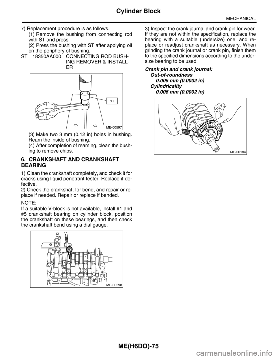
7) Replacement procedure is as follows.
(1) Remove the bushing from connecting rod
with ST and press.
(2) Press the bushing with ST after applying oil
on the periphery of bushing.
ST 18350AA000 CONNECTING ROD BUSH-
ING REMOVER & INSTALL-
ER
(3) Make two 3 mm (0.12 in) holes in bushing.
Ream the inside of bushing.
(4) After completion of reaming, clean the bush-
ing to remove chips.
6. CRANKSHAFT AND CRANKSHAFT
BEARING
1) Clean the crankshaft completely, and check it for
cracks using liquid penetrant tester. Replace if de-
fective.
2) Check the crankshaft for bend, and repair or re-
place if needed. Repair or replace if bended.
NOTE:
If a suitable V-block is not available, install #1 and
#5 crankshaft bearing on cylinder block, position
the crankshaft on these bearings, and then check
the crankshaft bend using a dial gauge.
3) Inspect the crank journal and crank pin for wear.
If they are not within the specification, replace the
bearing with a suitable (undersize) one, and re-
place or readjust crankshaft as necessary. When
grinding the crank journal or crank pin, finish them
to the specified dimensions according to the under-
size bearing to be used.
Crank pin and crank journal:
Out-of-roundness
0.005 mm (0.0002 in)
Cylindricality
0.006 mm (0.0002 in)
ST
ME-00597
ME-00598
ME-00184