Page 235 of 2453

EB-16
Front Door
EXTERIOR BODY PANELS
4. Front Door
A: REMOVAL
1) Disconnect the ground cable from battery.
2) Remove the front door trim.
MOVAL, Door Trim.>
3) Remove the outer mirror assembly.
GW-13, REMOVAL, Outer Mirror Assembly.>
4) Remove the front door speaker.
REMOVAL, Front Speaker.>
5) Remove the sealing cover.
MOVAL, Front Sealing Cover.>
6) Remove the front door glass.
REMOVAL, Front Door Glass.>
7) Remove the door sash, and remove the front
door regulator and motor assemblies.
10, REMOVAL, Front Regulator and Motor Assem-
bly.>
8) Remove the front inner remote.
REMOVAL, Front Inner Remote.>
9) Remove the front door latch assembly.
SL-36, REMOVAL, Front Door Latch and Door
Lock Actuator Assembly.>
10) Remove the front outer handle.
REMOVAL, Front Outer Handle.>
11) Remove the front door weather strip.
NOTE:
If the weather strip clip is removed with excessive
force, the weather strip may be damaged. Be sure
to use clip remover to remove.
12) Remove the bolts and nuts to remove the door
checker.
13) Remove the instrument panel lower cover or
glove box lower cover.
Instrument Panel Lower Cover.> or
REMOVAL, Glove Box.>
14) Disconnect the connector of door harness from
body harness.
15) Put a wooden block on jack and place jack un-
der the front door. Support the door with a jack to
protect it from damage.
16) Remove the door-side bolts for upper and low-
er hinges to remove front door panel.
17) Remove the door hinge from vehicle.
EB-00141
EB-00154
EB-00151
EB-00013
EB-00015
Page 290 of 2453
EI-48
Sun Visor
EXTERIOR/INTERIOR TRIM
21.Sun Visor
A: REMOVAL
1) Remove the cover, loosen the mounting screws,
and remove the sun visor.
2) Disconnect the connector. (Model with vanity
mirror light)
3) While pressing the (A) on the both side using flat
tip screwdriver, pull the sun visor hook to remove it.
B: INSTALLATION
Install in the reverse order of removal.
EI-00661
EI-00662
(A)
(A)
Page 297 of 2453
GW-2
General Description
GLASS/WINDOWS/MIRRORS
1. General Description
A: COMPONENT
1. FIXED GLASS
(1) Windshield glass (6) Spacer (10) Fastener
(2) Dam rubber (7) Fastener (11) Rear quarter glass
(3) Molding front (8) Seal (12) Rear gate glass
(4) Rearview mirror mount (9) Front quarter glass (13) Glass clip pin
(5) Locating pin
Page 298 of 2453
GW-3
General Description
GLASS/WINDOWS/MIRRORS
2. FRONT DOOR GLASS
(1) Glass (4) Regulator ASSYTightening torque: N·m (kgf-m, ft-lb)
(2) Door sash (5) Motor ASSYT1: 4.9 (0.5, 3.6)
(3) Glass run rubber (6) Weather stripT2: 7.4 (0.75, 5.5)
Page 299 of 2453
GW-4
General Description
GLASS/WINDOWS/MIRRORS
3. REAR DOOR GLASS
(1) Glass (4) Regulator ASSYTightening torque: N·m (kgf-m, ft-lb)
(2) Door sash (5) Motor ASSYT: 7.4 (0.75, 5.5)
(3) Glass run rubber (6) Weather strip
Page 300 of 2453
GW-5
General Description
GLASS/WINDOWS/MIRRORS
4. MIRROR
B: CAUTION
•When electrical connectors are disconnected, always conduct an operational check after connecting them
again.
•Avoid impact and damage to the glass.
C: PREPARATION TOOL
1. GENERAL TOOL
(1) Outer mirror (4) Side turn signal lightTightening torque: N·m (kgf-m, ft-lb)
(2) Mirror (5) Rearview mirrorT: 2 (0.2, 1.5)
(3) Scalp cap (6) Mount
TOOL NAME REMARKS
Circuit tester Used for checking voltage and continuity.
Piano wire Used for removing the window glass.
Windshield glass knife Used for removing the window glass.
TO RX® T20Used for removing and installing the rearview mirror.
GW-00476
(5)
(6)
(2)
(3)
(4)
(1)
T
Page 301 of 2453
GW-6
Power Window System
GLASS/WINDOWS/MIRRORS
2. Power Window System
A: WIRING DIAGRAM
B: INSPECTION
Symptom Repair order
All power windows do not operate.
1. Fuse (SBF-4)
2. Power window circuit breaker
3. Power window relay
4. Wiring Harness
5. Body integrated unit
Par ticular window does not operate.
1. Power window main switch
2. Power window sub switch
3. Power window motor
4. Wiring Harness
“Window Lock” does not operate. Power window main switch
Page 302 of 2453

GW-7
Power Window Control Switch
GLASS/WINDOWS/MIRRORS
3. Power Window Control
Switch
A: REMOVAL
1. MAIN SWITCH
1) Disconnect the ground cable from battery.
2) Peel the cover inside the hand grip, and remove
the screw.
3) Remove the power window switch cover assem-
bly.
4) Disconnect the harness connector.
5) Remove the clip, and remove the power window
main switch assembly.
2. SUB SWITCH
1) Disconnect the ground cable from battery.
2) Peel the cover inside the hand grip, and remove
the screw.
3) Remove the power window switch cover assem-
bly.
4) Disconnect the connector.
5) Detach the claw and remove the power window
sub switch.
B: INSTALLATION
Install in the reverse order of removal.
C: INSPECTION
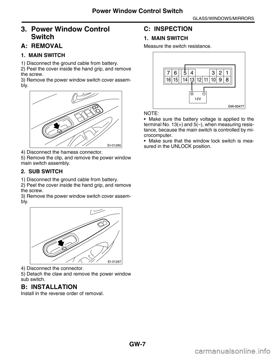
1. MAIN SWITCH
Measure the switch resistance.
NOTE:
•Make sure the battery voltage is applied to the
terminal No. 13(+) and 5(–), when measuring resis-
tance, because the main switch is controlled by mi-
crocomputer.
•Make sure that the window lock switch is mea-
sured in the UNLOCK position.EI-01286
EI-01287