Page 327 of 2453
GW-32
Wiper Deicer Switch
GLASS/WINDOWS/MIRRORS
2. CHECK SWITCH
Remove the wiper deicer switch, and measure the
switch resistance.
Replace the wiper deicer switch if faulty.
Switch position Terminal No. Standard
OFF1 and 21 MΩ or more
ON Less than 1 Ω
GW-00330
914
7654321
81311101512
Page 552 of 2453
LI-19
Side Turn Signal Light Assembly
LIGHTING SYSTEM
17.Side Turn Signal Light As-
sembly
A: REMOVAL
1) Disconnect the ground cable from battery.
2) Remove the mirror.
MENT, Outer Mirror.>
3) Remove the scalp cap.
PLACEMENT, Scalp Cap.>
4) Disconnect the harness connector, remove the 3
mounting screws and then remove the side turn
signal light assembly.
B: INSTALLATION
Install in the reverse order of removal.
C: INSPECTION
1) Install the side turn signal light assembly and
check that it blinks normally.
2) If it does not blink normally, replace the side turn
signal light assembly with a new one.
NOTE:
Because a LED (Light Emitting Diode) is used for
the side turn signal light, replace the side turn sig-
nal light as an assembly if the LED does not turn
on.
LI-00293
Page 749 of 2453
BR-35
Brake Pipe
BRAKE
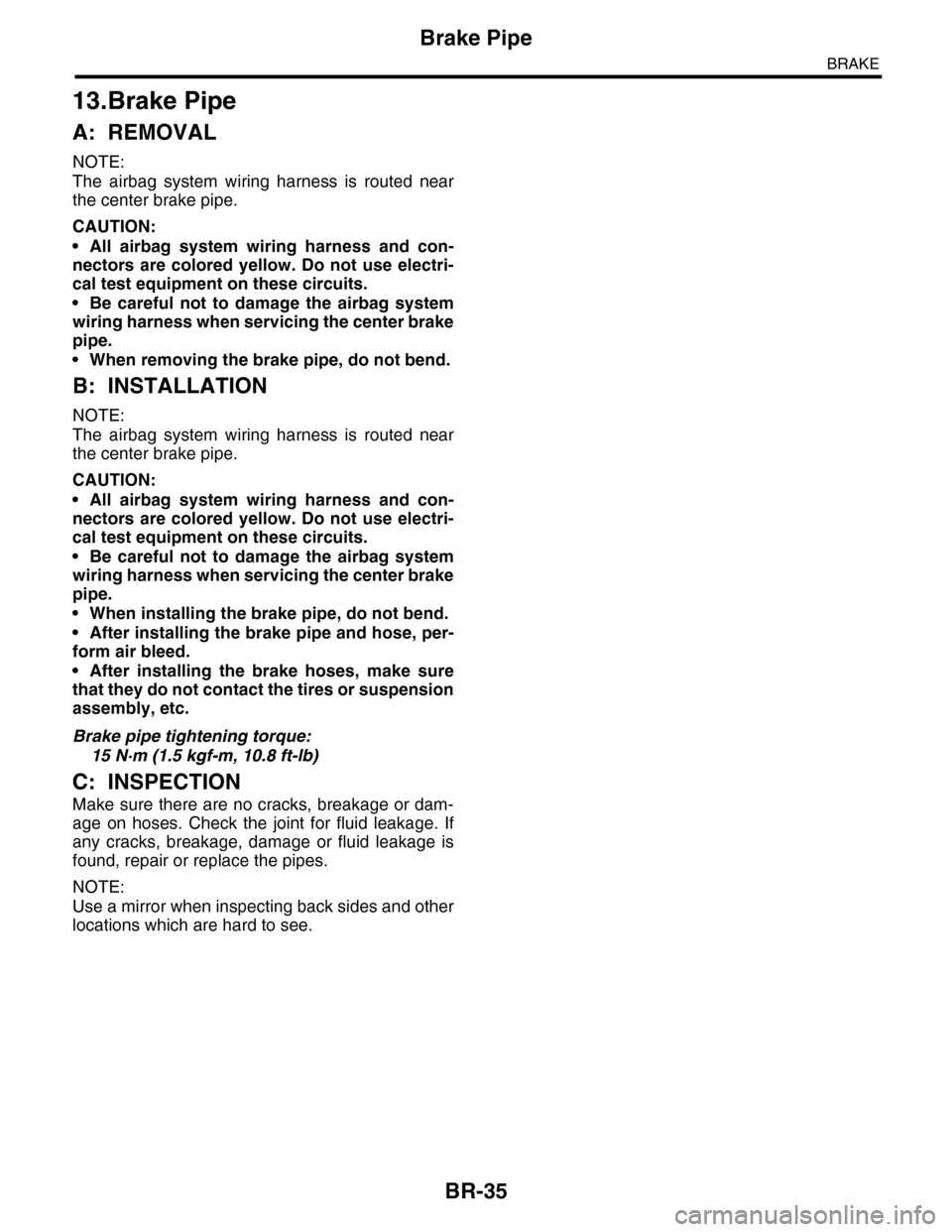
13.Brake Pipe
A: REMOVAL
NOTE:
The airbag system wiring harness is routed near
the center brake pipe.
CAUTION:
•All airbag system wiring harness and con-
nectors are colored yellow. Do not use electri-
cal test equipment on these circuits.
•Be careful not to damage the airbag system
wiring harness when servicing the center brake
pipe.
•When removing the brake pipe, do not bend.
B: INSTALLATION
NOTE:
The airbag system wiring harness is routed near
the center brake pipe.
CAUTION:
•All airbag system wiring harness and con-
nectors are colored yellow. Do not use electri-
cal test equipment on these circuits.
•Be careful not to damage the airbag system
wiring harness when servicing the center brake
pipe.
•When installing the brake pipe, do not bend.
•After installing the brake pipe and hose, per-
form air bleed.
•After installing the brake hoses, make sure
that they do not contact the tires or suspension
assembly, etc.
Brake pipe tightening torque:
15 N·m (1.5 kgf-m, 10.8 ft-lb)
C: INSPECTION
Make sure there are no cracks, breakage or dam-
age on hoses. Check the joint for fluid leakage. If
any cracks, breakage, damage or fluid leakage is
found, repair or replace the pipes.
NOTE:
Use a mirror when inspecting back sides and other
locations which are hard to see.
Page 2002 of 2453
PM-19
Brake Line
PERIODIC MAINTENANCE SERVICES
13.Brake Line
A: INSPECTION
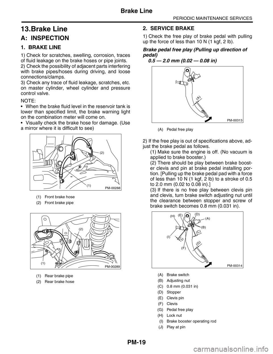
1. BRAKE LINE
1) Check for scratches, swelling, corrosion, traces
of fluid leakage on the brake hoses or pipe joints.
2) Check the possibility of adjacent parts interfering
with brake pipes/hoses during driving, and loose
connections/clamps.
3) Check any trace of fluid leakage, scratches, etc.
on master cylinder, wheel cylinder and pressure
control valve.
NOTE:
•When the brake fluid level in the reservoir tank is
lower than specified limit, the brake warning light
on the combination meter will come on.
•Visually check the brake hose for damage. (Use
a mirror where it is difficult to see)
2. SERVICE BRAKE
1) Check the free play of brake pedal with pulling
up the force of less than 10 N (1 kgf, 2 lb).
Brake pedal free play (Pulling up direction of
pedal)
0.5 — 2.0 mm (0.02 — 0.08 in)
2) If the free play is out of specifications above, ad-
just the brake pedal as follows.
(1) Make sure the engine is off. (No vacuum is
applied to brake booster.)
(2) There should be play between brake boost-
er clevis and pin at brake pedal installing por-
tion. [Pulling up the brake pedal pad with a force
of less than 10 N (1 kgf, 2 lb) to a stroke of 0.5
to 2.0 mm (0.02 to 0.08 in).]
(3) If there is no free play between clevis pin
and clevis, turn brake switch adjusting nut until
the clearance between stopper and screw of
brake switch becomes 0.8 mm (0.031 in).
(1) Front brake hose
(2) Front brake pipe
(1) Rear brake pipe
(2) Rear brake hose
PM-00288
(2)
(1)
PM-00289(1)
(2)
(A) Pedal free play
(A) Brake switch
(B) Adjusting nut
(C) 0.8 mm (0.031 in)
(D) Stopper
(E) Clevis pin
(F) Clevis
(G) Pedal free play
(H) Lock nut
(I) Brake booster operating rod
(J) Play at pin
PM-00313
(A)
PM-00314
(G)
(A)(D)(E)
(B)
(C)
(F)
(J)(I)
(H)
Page 2304 of 2453
WI-20
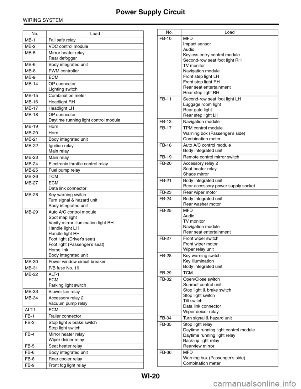
Power Supply Circuit
WIRING SYSTEM
No. Load
MB-1 Fail safe relay
MB-2 VDC control module
MB-5 Mirror heater relay
Rear defogger
MB-6 Body integrated unit
MB-8 PWM controller
MB-9 ECM
MB-14 OP connector
Lighting switch
MB-15 Combination meter
MB-16 Headlight RH
MB-17 Headlight LH
MB-18 OP connector
Daytime running light control module
MB-19 Horn
MB-20 Horn
MB-21 Body integrated unit
MB-22 Ignition relay
Main relay
MB-23 Main relay
MB-24 Electronic throttle control relay
MB-25 Fuel pump relay
MB-26 TCM
MB-27 ECM
Data link connector
MB-28 Key warning switch
Tu r n s i g n a l & h a z a r d u n i t
Body integrated unit
MB-29 Auto A/C control module
Spot map light
Va n i t y m i r r o r i l l u m i n a t i o n l i g h t R H
Handle light LH
Handle light RH
Foot light (Driver’s seat)
Foot light (Passenger’s seat)
Home link
Body integrated unit
MB-30 Power window circuit breaker
MB-31 F/B fuse No. 16
MB-32 ALT-1
ECM
Par king light switch
MB-33 Blower fan relay
MB-34 Accessory relay 2
Va c u u m p u m p r e l ay
ALT-1 ECM
FB-1 Trailer connector
FB-3 Stop light & brake switch
Stop light switch
FB-4 Mirror heater relay
Wiper deicer relay
FB-5 Seat heater relay
FB-6 Body integrated unit
FB-8 Rear cooler relay
FB-9 Front fog light relay
FB-10 MFD
Impact sensor
Audio
Keyless entr y control module
Second-row seat foot light RH
TV monitor
Navigation module
Fr o n t s te p li gh t LH
Fr o n t s te p li gh t RH
Rear seat entertainment
Rear step light RH
FB-11 Second-row seat foot light LH
Luggage room light
Rear gate light
Rear step light LH
FB-13 Navigation module
FB-17 TPM control module
War ning box (Passenger’s side)
Combination meter
FB-18 Auto A/C control module
Body integrated unit
FB-19 Remote control mirror switch
FB-20 Accessory relay 2
Seat heater relay
Shade mirror
FB-21 Body integrated unit
Rear accessory power supply socket
FB-23 Rear wiper motor
FB-24 Body integrated unit
Rear washer motor
FB-25 MFD
Audio
TV monitor
Navigation module
Rear seat entertainment
FB-27 Front wiper switch
Fr o n t wi p er mo t or
Wiper relay unit
FB-28 Key warning switch
Key illumination
Body integrated unit
FB-29 TCM
FB-32 Open/Close switch
Sunroof control unit
Stop light & brake switch
Stop light switch
Tilt switch
Data link connector
Wiper deicer relay
FB-34 Turn signal & hazard unit
FB-35 Stop light relay
Daytime running light control module
Daytime running light relay
Back-up light relay
Rearview mirror
FB-36 MFD
War ning box (Passenger’s side)
Combination meter
No. Load
Page 2306 of 2453
WI-22
Ground Circuit
WIRING SYSTEM
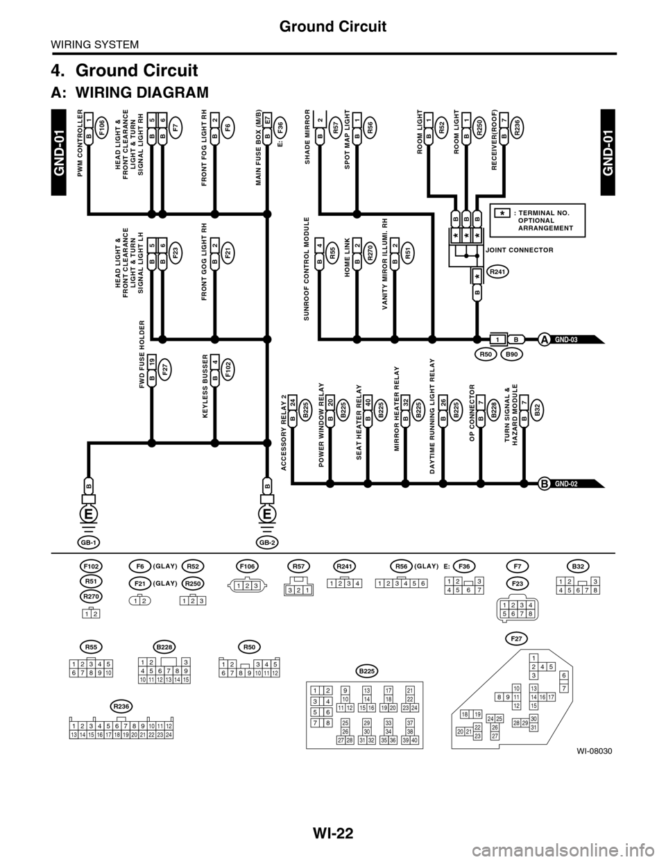
4. Ground Circuit
A: WIRING DIAGRAM
WI-08030
GND-01GND-01
F106B1
PWM CONTROLLER
F6(GLAY)(GLAY)
(GLAY)
F102
R270
F21
F7F6B2
FRONT FOG LIGHT RH
E:
F36B E7
MAIN FUSE BOX (M/B)
R55B4R51B2
VANITY MIROR ILLUMI. RH
R270B2
HOME LINK
R52B1
1
ROOM LIGHT
R250R57B1
ROOM LIGHT
R236B7
RECEIVER(ROOF)SHADE MIRROR
B225B 26
DAYTIME RUNNING LIGHT RELAY
F27B 19FWD FUSE HOLDER
F102B4
KEYLESS BUSSERB225B 24
ACCESSORY RELAY 2
B225B 40
SEAT HEATER RELAY
B225B 20
POWER WINDOW RELAY
B228B7
OP CONNECTOR
B32B7
TURN SIGNAL &HAZARD MODULE
B225B 32
MIRROR HEATER RELAY
GND-02B
GB-1
B
GB-2
B
B
12
12
R52
R250
123
F7
F23
R57
B228
131415
123456789101112
F27
13141516 17
27
24 252620 212223
29303128
89101112
12534
7
6
1918
B225
13141516
17
27
24
2526
20
212223
293031283235
33343738393640
8
9101112
12
534
761918
B32
12345678
SUNROOF CONTROL MODULE
HEAD LIGHT &FRONT CLEARANCELIGHT & TURNSIGNAL LIGHT RH
GND-03A
R51
234510 111678912
R50
F106
123
B A16B5B6
F23F21B2
FRONT GOG LIGHT RH
HEAD LIGHT &FRONT CLEARANCELIGHT & TURNSIGNAL LIGHT LH
B A16B5B6
R56B
SPOT MAP LIGHT
JOINT CONNECTOR
R241
***
*
B90R50
B
B
BBB
1
*: TERMINAL NO. OPTIONAL ARRANGEMENT
123
R56
1234561234567
F36E:
R55
12346789510
R241
1234
R236
123 8910413 14 15 1656711121718192021222324
2
34561278
Page 2309 of 2453
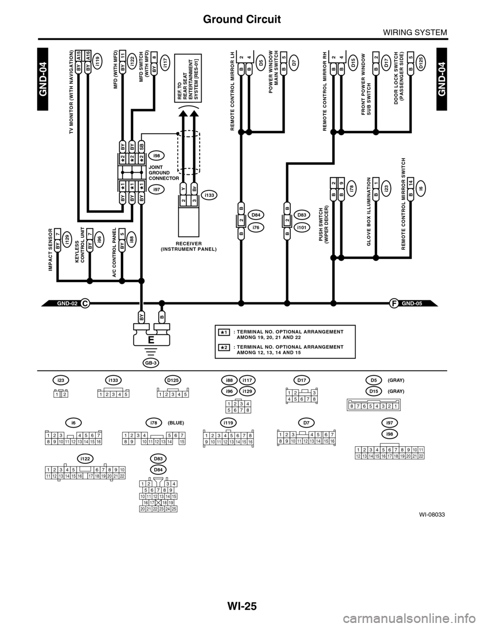
WI-25
Ground Circuit
WIRING SYSTEM
WI-08033
GND-04GND-04
i117BYi122BY 11
8
A/C CONTROL PANEL
i88BY 5
23
GND-05F
KEYLESS CONTROL UNIT
i96BY 7
IMPACT SENSOR
i129BY 7
TV MONITOR (WITH NAVIGATION)
i119BY A15BY A16
GND-02C
GB-3
BBY
D83
MFD (WITH MFD)MFD SWITCH (WITH MFD)
i96
12345678
i6
42
14
REMOTE CONTROL MIRROR SWITCH
i97i133
i98
JOINTGROUNDCONNECTOR
RECEIVER(INSTRUMENT PANEL)
2*2*
1*1*
2*
1*
BYBi231
GLOVE BOX ILLUMINATION
Bi789
PUSH SWITCH(WIPER DEICER)
B
2
BBYBY
SBBYBY
YBr
REF. TOREAR SEATENTERTAINMENT SYSTEM [RES-01]
: TERMINAL NO. OPTIONAL ARRANGEMENT AMONG 19, 20, 21 AND 22
: TERMINAL NO. OPTIONAL ARRANGEMENT AMONG 12, 13, 14 AND 15
1*
2*
D125
5
DOOR LOCK SWITCH(PASSENGER SIDE)
BD17
2
FRONT POWER WINDOW SUB SWITCH
POWER WINDOW
MAIN SWITCH
BD75
BD15
REMOTE CONTROL MIRROR RH
BB
42D5
REMOTE CONTROL MIRROR LH
BB
i1012D83
B
B
i762D84
B
B
D84
i88
i129
i117
567821943
10
2422 23 25
1112131415161718192021
i98
i97
12345678910111213141516171819202122
D7
12345689101112131514716
D17
12345678
D5
D15
87654321
(GRAY)
(GRAY)
i6
12345678910111213141516
i119
123 8910412 13 14 15 1656711
i133
12345
12345678910111213141516171819202122
i122
i78
123456789101112131415
(BLUE)
i23
12
D125
12345
Page 2374 of 2453
WI-90
Back–up Light System
WIRING SYSTEM
25.Back–up Light System
A: WIRING DIAGRAM
WI-08096
BACK/L-01BACK/L-01
FB-35F/B FUSE NO. 18(IG)
TOPOWER SUPPLYCIRCUIT
B11
BrR
B55B:
GL
TCM
1 BrY
R57
B90
R50
REARVIEWMIRROR
BrY
6
BrYR2
B97
BrY
BrY
5
B
BACK-UPLIGHTLH
D91
2
BrY
B
1
BACK-UPLIGHTRH
2
BrY
1
6
BrYB228
OPCONNECTOR
B
D87
123410 11 1219 20 21135614 1578916 17 1822 23 24
123456789101112
B356
34
12D91
12
B55B:
D87
(GRAY)
R38
R224
R225
D33
B228
131415
123456789101112
R247R215
2
B
B
R37
D34
REF. TO GROUNDCIRCUIT [GND-06]
R50
123456789101112
GL
1
GL
4
2
BrR
3
BrY
BACK-UPLIGHT RELAY
B356
BrY
BrY
JOINTCONNECTOR
R224
R2251*
2*
BrY
BrY
BrY
THROUGHJOINTCONNECTOR
D33
R38
BrY
BrY
3
10
87
: TERMINAL NO. OPTIONAL ARRANGEMENT BETWEEN 7 AND 8
: TERMINAL NO. OPTIONAL ARRANGEMENT BETWEEN 11 AND 12
1*
2*
R57
321
R215
12
10115634897131412
D34
121
B97
1234567891011 121316 17 18 19 201415
(GRAY)
(GRAY)