2009 SUBARU TRIBECA wheel bolt torque
[x] Cancel search: wheel bolt torquePage 14 of 2453

AB-15
Driver’s Airbag Module
AIRBAG SYSTEM
4. Driver’s Airbag Module
A: REMOVAL
CAUTION:
Refer to “CAUTION” of “General Description”
before handling the airbag module.
1) Position the front wheels straight ahead. (After
moving a vehicle more than 5 m (16 ft) with front
wheels positioned straight ahead, make sure that
the vehicle moves straight ahead).
2) Turn the ignition switch to OFF.
3) Disconnect the ground cable from battery and
wait for at least 20 seconds before starting work.
4) Using TORX® BIT T30 (1), remove the two
TORX® bolts on the side of steering wheel.
5) Disconnect the horn harness.
6) Disconnect the airbag connector on the back of
airbag module, and then remove the airbag mod-
ule.
7) Refer to “CAUTION” for handling of a removed
airbag module.
B: INSTALLATION
CAUTION:
•Refer to “CAUTION” of “General Description”
before handling the airbag module.
•To prevent the misconnection, the connector
is colored. Connect the harness side connector
to the same color of module side connector.
Install in the reverse order of removal.
Tightening torque:
10 N·m (1.0 kgf-m, 7.2 ft-lb)
C: INSPECTION
CAUTION:
Refer to “CAUTION” of “General Description”
before handling the airbag module.
Check for the following, and replace the damaged
parts with new parts.
•Airbag module, harness, connector and mount-
ing bracket are damaged.
Inspection Locations After a Collision.>
CC-00018
(1)
AB-00622
Page 728 of 2453

BR-14
Front Disc Rotor
BRAKE
3. Front Disc Rotor
A: REMOVAL
1) Lift-up the vehicle, and remove the front wheels.
2) Remove the caliper body and the support from
housing, and suspend it from the strut using a wire.
3) Remove the disc rotor.
NOTE:
If it is difficult to remove the disc rotor from the hub,
drive an 8 mm bolt into the threaded section (B) of
the rotor, then remove the rotor.
4) Remove mud and foreign matter from the caliper
body assembly and support.
B: INSTALLATION
1) Install the disc rotor.
2) Install the caliper body and the support to hous-
ing.
Tightening torque:
120 N·m (12.2 kgf-m, 88.5 ft-lb)
3) Install the front wheels.
C: INSPECTION
1) Check the front wheel bearing play and axle hub
runout before the inspection of disc rotor runout
limit.
2) Secure the disc rotor by tightening the five wheel
nuts.
3) Set a dial gauge 10 mm (0. 39 in) inward from
the disc rotor outer circumference. Rotate the disc
rotor to check runout. If the disc rotor runout ex-
ceeds the limit, replace with a new disc rotor. After
grinding, check disk rotor thickness according to
step 4).
Disc rotor runout limit:
0.05 mm (0.0020 in)
4) Set a micrometer 10 mm (0.39 in) inward from
the disc rotor outer perimeter, and then measure
the disc rotor thickness. If the thickness of the disc
rotor exceeds the service limit, replace with a new
disc rotor.
BR-00017
B
A
BR-00018
Specification LimitDisc rotor
outer diameter
Disc rotor thick-
ness A
mm (in)
30 (1.18) 28 (1.10) 316 (12.44)
BR-00019
B
A
BR-00018
Page 729 of 2453

BR-15
Front Disc Brake Assembly
BRAKE
4. Front Disc Brake Assembly
A: REMOVAL
CAUTION:
Do not allow brake fluid to come in contact with
vehicle body. If it does, wash off with water and
wipe away completely.
1) Lift-up the vehicle, and remove the front wheels.
2) Remove the union bolt, and disconnect the
brake hose from the caliper body assembly.
3) Remove the bolt securing the lock pin to caliper
body.
4) Raise the caliper body, and then move it toward
vehicle center to separate it from the support.
5) Remove the support from housing.
NOTE:
Remove the support only when replacing the rotor
or support. It need not be removed when servicing
the caliper body assembly.
6) Remove mud and foreign matter from the caliper
body assembly and support.
B: INSTALLATION
1) Install the support to the housing.
Tightening torque:
120 N·m (12.2 kgf-m, 88.5 ft-lb)
2) Apply a thin coat of Molykote M7439 to the pad
clip.
3) Apply a thin coat of Molykote AS880N (Part No.
K0777YA010) to the contact surface between pad
and inner shim.
4) Apply a thin coat of Molykote AS880N (Part No.
K0779YA010) to the three contact surfaces be-
tween inner shim and outer shim of outer pads.
BR-00021
BR-00022
BR-00023
BR-00340
BR-00238
BR-00341
Page 733 of 2453

BR-19
Rear Brake Pad
BRAKE
5. Rear Brake Pad
A: REMOVAL
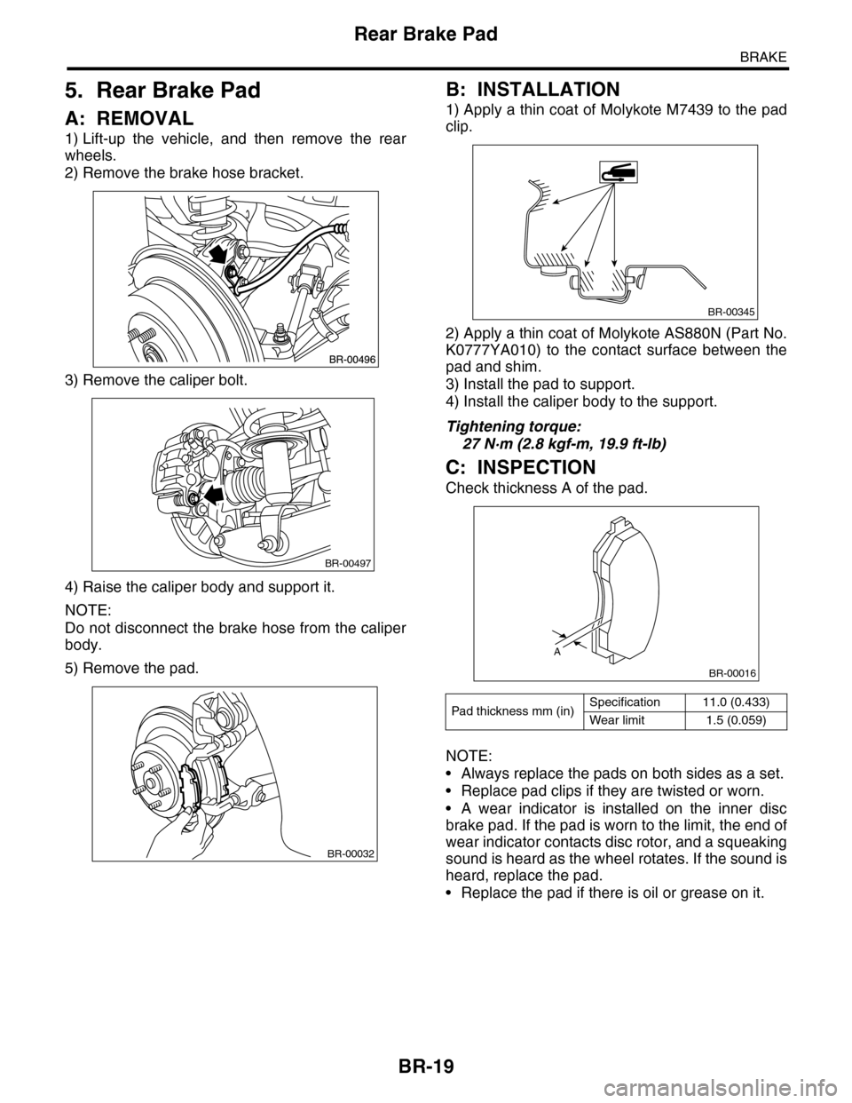
1) Lift-up the vehicle, and then remove the rear
wheels.
2) Remove the brake hose bracket.
3) Remove the caliper bolt.
4) Raise the caliper body and support it.
NOTE:
Do not disconnect the brake hose from the caliper
body.
5) Remove the pad.
B: INSTALLATION
1) Apply a thin coat of Molykote M7439 to the pad
clip.
2) Apply a thin coat of Molykote AS880N (Part No.
K0777YA010) to the contact surface between the
pad and shim.
3) Install the pad to support.
4) Install the caliper body to the support.
Tightening torque:
27 N·m (2.8 kgf-m, 19.9 ft-lb)
C: INSPECTION
Check thickness A of the pad.
NOTE:
•Always replace the pads on both sides as a set.
•Replace pad clips if they are twisted or worn.
•A wear indicator is installed on the inner disc
brake pad. If the pad is worn to the limit, the end of
wear indicator contacts disc rotor, and a squeaking
sound is heard as the wheel rotates. If the sound is
heard, replace the pad.
•Replace the pad if there is oil or grease on it.
BR-00497
BR-00032
Pad thickness mm (in)Specification 11.0 (0.433)
Wear limit 1.5 (0.059)
BR-00345
A
BR-00016
Page 734 of 2453

BR-20
Rear Disc Rotor
BRAKE
6. Rear Disc Rotor
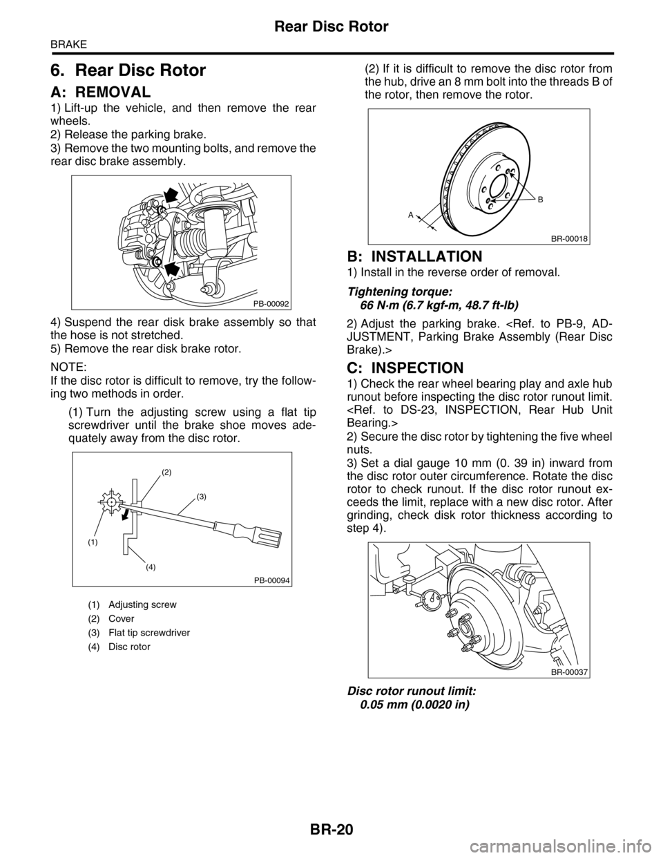
A: REMOVAL
1) Lift-up the vehicle, and then remove the rear
wheels.
2) Release the parking brake.
3) Remove the two mounting bolts, and remove the
rear disc brake assembly.
4) Suspend the rear disk brake assembly so that
the hose is not stretched.
5) Remove the rear disk brake rotor.
NOTE:
If the disc rotor is difficult to remove, try the follow-
ing two methods in order.
(1) Turn the adjusting screw using a flat tip
screwdriver until the brake shoe moves ade-
quately away from the disc rotor.
(2) If it is difficult to remove the disc rotor from
the hub, drive an 8 mm bolt into the threads B of
the rotor, then remove the rotor.
B: INSTALLATION
1) Install in the reverse order of removal.
Tightening torque:
66 N·m (6.7 kgf-m, 48.7 ft-lb)
2) Adjust the parking brake.
Brake).>
C: INSPECTION
1) Check the rear wheel bearing play and axle hub
runout before inspecting the disc rotor runout limit.
2) Secure the disc rotor by tightening the five wheel
nuts.
3) Set a dial gauge 10 mm (0. 39 in) inward from
the disc rotor outer circumference. Rotate the disc
rotor to check runout. If the disc rotor runout ex-
ceeds the limit, replace with a new disc rotor. After
grinding, check disk rotor thickness according to
step 4).
Disc rotor runout limit:
0.05 mm (0.0020 in)
(1) Adjusting screw
(2) Cover
(3) Flat tip screwdriver
(4) Disc rotor
PB-00092
(1)
(4)
(2)
(3)
PB-00094
B
A
BR-00018
BR-00037
Page 736 of 2453

BR-22
Rear Disc Brake Assembly
BRAKE
7. Rear Disc Brake Assembly
A: REMOVAL
CAUTION:
Do not allow brake fluid to come in contact with
vehicle body. If it does, wash off with water and
wipe away completely.
1) Lift-up the vehicle, and then remove the rear
wheels.
2) Disconnect the brake hose from caliper body as-
sembly.
3) Remove the caliper lower bolt.
4) Raise the caliper body, and then move it toward
vehicle center to separate it from the support.
5) Remove the support from housing.
NOTE:
Remove the support only when replacing the rotor
or support. It need not be removed when servicing
the caliper body assembly.
6) Remove mud and foreign matter from the caliper
body assembly and support.
CAUTION:
Be careful not to allow foreign matter to enter
the brake hose connector.
B: INSTALLATION
1) Install the support to the housing.
Tightening torque:
66 N·m (6.7 kgf-m, 48.7 ft-lb)
2) Apply a thin coat of Molykote M7439 to the pad
clip.
3) Apply a thin coat of Molykote AS880N (Part No.
K0777YA010) to the contact surface between the
pad and shim.
4) Install the pad to support.
5) Install the caliper body to the support.
Tightening torque:
27 N·m (2.8 kgf-m, 19.9 ft-lb)
6) Connect the brake hose using a new brake hose
gasket.
Tightening torque:
18 N·m (1.8 kgf-m, 13.0 ft-lb)
7) Bleed air from the brake system.
C: DISASSEMBLY
1) Remove the piston boot.
2) Place a wooden block in the caliper body as
shown in the figure to prevent the piston from jump-
ing out and being damaged.
3) Gradually apply compressed air via the brake
hose installation hole to push the piston out.
BR-00498
BR-00345
(1) Place a wood block of 30 mm (1.18 in) width.
BR-00041
(1)BR-00042
Page 748 of 2453

BR-34
Brake Hose
BRAKE
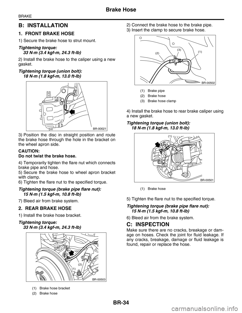
B: INSTALLATION
1. FRONT BRAKE HOSE
1) Secure the brake hose to strut mount.
Tightening torque:
33 N·m (3.4 kgf-m, 24.3 ft-lb)
2) Install the brake hose to the caliper using a new
gasket.
Tightening torque (union bolt):
18 N·m (1.8 kgf-m, 13.0 ft-lb)
3) Position the disc in straight position and route
the brake hose through the hole in the bracket on
the wheel apron side.
CAUTION:
Do not twist the brake hose.
4) Temporarily tighten the flare nut which connects
brake pipe and hose.
5) Secure the brake hose to wheel apron bracket
with clamp.
6) Tighten the flare nut to the specified torque.
Tightening torque (brake pipe flare nut):
15 N·m (1.5 kgf-m, 10.8 ft-lb)
7) Bleed air from brake system.
2. REAR BRAKE HOSE
1) Install the brake hose bracket.
Tightening torque:
33 N·m (3.4 kgf-m, 24.3 ft-lb)
2) Connect the brake hose to the brake pipe.
3) Insert the clamp to secure brake hose.
4) Install the brake hose to rear brake caliper using
a new gasket.
Tightening torque (union bolt):
18 N·m (1.8 kgf-m, 13.0 ft-lb)
5) Tighten the flare nut to the specified torque.
Tightening torque (brake pipe flare nut):
15 N·m (1.5 kgf-m, 10.8 ft-lb)
6) Bleed air from the brake system.
C: INSPECTION
Make sure there are no cracks, breakage or dam-
age on hoses. Check the joint for fluid leakage. If
any cracks, breakage, damage or fluid leakage is
found, repair or replace the hose.
(1) Brake hose bracket
(2) Brake hose
BR-00021
BR-00503
(1)
(2)
(1) Brake pipe
(2) Brake hose
(3) Brake hose clamp
(1) Brake hose
BR-00502
(1)(2)(3)
BR-00501
(1)
Page 755 of 2453

BR-41
General Diagnostic Table
BRAKE
18.General Diagnostic Table
A: INSPECTION
Trouble and possible causeCorrective action
1. Insufficient braking
performance
(1) Fluid leakage from the hydraulic mechanism Correct or replace. (cup, piston seal, piston
boot, master cylinder piston kit, pipe or
hose)
(2) Entry of air into the hydraulic mechanism Bleed air.
(3) Wear, deteriorated surface material, water or fluid on
lining
Replace, grind or clean.
(4) Improper operation of master cylinder, disc caliper,
brake booster or check valve
Correct or replace.
2. Unstable or uneven
braking
(1) Fluid on lining or rotor Correct the cause of fluid leakage, and
clean or replace.
(2) Rotor defective Repair or replace the rotor.
(3) Improper lining contact, deteriorated surface, deterio-
rated or wear lining material
Repair by grinding, or replace.
(4) Deformed back plate Repair or replace.
(5) Over inflation of tires Adjust air pressure.
(6) Defective wheel alignment Adjust alignment.
(7) Loose back plate or suppor t installation bolt Tighten to the specified torque.
(8) Faulty wheel bearing Replace.
(9) Defective hydraulic system Replace the cylinder, brake pipe or hose.
(10) Unstable effect of parking brake Check, adjust or replace the rear brake and
cable system.
3. Excessive pedal
stroke
(1) Entry of air into the hydraulic mechanism Bleed air.
(2) Excessive play in the master cylinder push rod Adjust.
(3) Fluid leakage from the hydraulic mechanism Correct or replace. (cup, piston seal, piston
boot, master cylinder piston kit, pipe or
hose)
(4) Improper lining contact or worn lining Correct or replace.
4. Brake dragging or
improper brake
return
(1) Insufficient pedal play Adjust play.
(2) Improper master cylinder return Clean or replace the cylinder.
(3) Clogged hydraulic system Replace.
(4) Improper return or adjustment of parking brake Repair or adjust.
(5) Weakened spring tension or breakage of shoe return
spring
Replace the spring.
(6) Improper disc caliper operation Correct or replace.
(7) Faulty wheel bearing Replace.
Brake noise (1)
(creaking sound)
(1) Hardened or deteriorated brake pad Replace the pad.
(2) Worn brake pad Replace the pad.
(3) Loose back plate or suppor t installation bolt Tighten to the specified torque.
(4) Loose wheel bearing Tighten to the specified torque.
(5) Dir ty rotor Clean the rotor, or clean and replace brake
assembly.
6. Brake noise (2)
(hissing sound)
(1) Worn brake pad Replace the pad.
(2) Improperly installed pad Correct or replace the pad.
(3) Loose or bent rotor Retighten or replace.
7. Brake noise (3)
(click sound)
Excessively worn pad or suppor t Replace the pad or the suppor t.