2009 SUBARU TRIBECA wheel bolt torque
[x] Cancel search: wheel bolt torquePage 945 of 2453

RS-12
Rear Shock Absorber
REAR SUSPENSION
6. Rear Shock Absorber
A: REMOVAL
1) Remove the strut cap of quarter trim.
2) Lift-up the vehicle, and then remove the rear
wheels.
3) Remove the nut and detach the rear stabilizer link.
4) Remove the bolts on the bottom side of the
shock absorber.
5) Detach the rear lateral link.
6) Remove the nuts of the shock absorber mount.
7) Remove the shock absorber.
B: INSTALLATION
NOTE:
•Be sure to use a new self-locking nut.
•Always tighten the stabilizer bushing in the state
where the vehicle is at curb weight and the wheels
are in full contact with the ground.
1) Install in the reverse order of removal.
CAUTION:
Attach so that the protrusion on the top of the
mount is pointed towards the front of the vehicle.
Tightening torque:
Refer to “COMPONENT” of “General Descrip-
tion” for the tightening torque.
2) Check the wheel alignment and adjust it if nec-
essary.
C: DISASSEMBLY
Refer to “Front Strut” for disassembly procedure.
D: ASSEMBLY
Refer to “Front Strut” for installation procedures.
E: INSPECTION
Refer to “Front Strut” for inspection procedures.
RS-00185
RS-00186
RS-00187
RS-00188
(1) Mount
(2) Protrusion por tion
(3) Front side of vehicle
Page 947 of 2453
RS-14
Front Lateral Link
REAR SUSPENSION
7. Front Lateral Link
A: REMOVAL
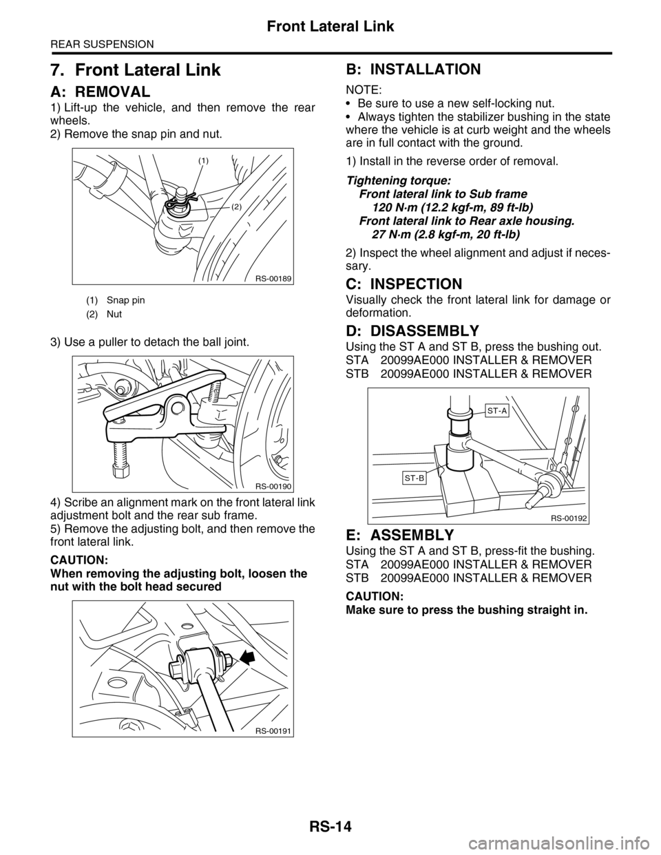
1) Lift-up the vehicle, and then remove the rear
wheels.
2) Remove the snap pin and nut.
3) Use a puller to detach the ball joint.
4) Scribe an alignment mark on the front lateral link
adjustment bolt and the rear sub frame.
5) Remove the adjusting bolt, and then remove the
front lateral link.
CAUTION:
When removing the adjusting bolt, loosen the
nut with the bolt head secured
B: INSTALLATION
NOTE:
•Be sure to use a new self-locking nut.
•Always tighten the stabilizer bushing in the state
where the vehicle is at curb weight and the wheels
are in full contact with the ground.
1) Install in the reverse order of removal.
Tightening torque:
Front lateral link to Sub frame
120 N·m (12.2 kgf-m, 89 ft-lb)
Front lateral link to Rear axle housing.
27 N·m (2.8 kgf-m, 20 ft-lb)
2) Inspect the wheel alignment and adjust if neces-
sary.
C: INSPECTION
Visually check the front lateral link for damage or
deformation.
D: DISASSEMBLY
Using the ST A and ST B, press the bushing out.
STA 20099AE000 INSTALLER & REMOVER
STB 20099AE000 INSTALLER & REMOVER
E: ASSEMBLY
Using the ST A and ST B, press-fit the bushing.
STA 20099AE000 INSTALLER & REMOVER
STB 20099AE000 INSTALLER & REMOVER
CAUTION:
Make sure to press the bushing straight in.
(1) Snap pin
(2) Nut
RS-00189
(2)
(1)
RS-00190
RS-00191
RS-00192
ST-A
ST-B
Page 948 of 2453
RS-15
Rear Lateral Link
REAR SUSPENSION
8. Rear Lateral Link
A: REMOVAL
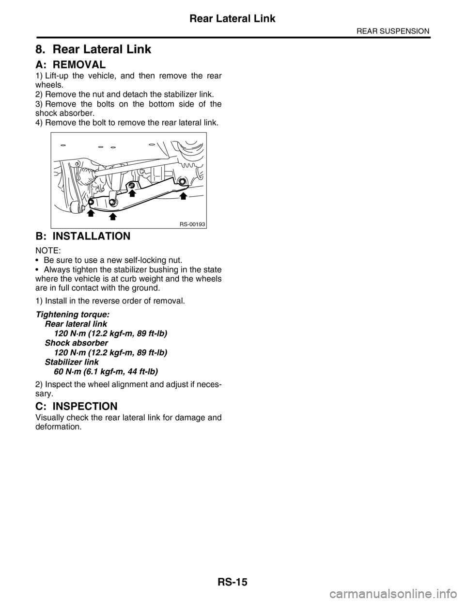
1) Lift-up the vehicle, and then remove the rear
wheels.
2) Remove the nut and detach the stabilizer link.
3) Remove the bolts on the bottom side of the
shock absorber.
4) Remove the bolt to remove the rear lateral link.
B: INSTALLATION
NOTE:
•Be sure to use a new self-locking nut.
•Always tighten the stabilizer bushing in the state
where the vehicle is at curb weight and the wheels
are in full contact with the ground.
1) Install in the reverse order of removal.
Tightening torque:
Rear lateral link
120 N·m (12.2 kgf-m, 89 ft-lb)
Shock absorber
120 N·m (12.2 kgf-m, 89 ft-lb)
Stabilizer link
60 N·m (6.1 kgf-m, 44 ft-lb)
2) Inspect the wheel alignment and adjust if neces-
sary.
C: INSPECTION
Visually check the rear lateral link for damage and
deformation.
RS-00193
Page 949 of 2453

RS-16
Rear Sub Frame
REAR SUSPENSION
9. Rear Sub Frame
A: REMOVAL
1) Separate the front exhaust pipe and rear ex-
haust pipe.
2) Remove the rear exhaust pipe and muffler.
3) Remove the propeller shaft.
4) Remove the spare tire hoist.
5) Remove the rear parking brake cable from the
parking brake assembly.
6) Detach the brake hose, and remove the rear
brake caliper from the vehicle.
7) Disconnect the ABS wheel speed sensor con-
nector.
8) Remove the bolts on the bottom side of the
shock absorber.
9) Support the sub frame using a jack.
10) Remove the front sub frame.
11) Remove the rear sub frame support.
12) Remove the rear sub frame.
B: INSTALLATION
NOTE:
•Be sure to use a new self-locking nut.
•Always tighten the stabilizer bushing in the state
where the vehicle is at curb weight and the wheels
are in full contact with the ground.
1) Install in the reverse order of removal.
Tightening torque:
Refer to “COMPONENT” of “General Descrip-
tion” for the tightening torque.
2) Bleed air from brake system.
3) Inspect the wheel alignment and adjust if neces-
sary.
C: INSPECTION
Check the removed parts for wear, damage and
crack, and repair or replace them if faulty.
RS-00194
RS-00195
RS-00196
RS-00197
RS-00198
Page 950 of 2453
RS-17
General Diagnostic Table
REAR SUSPENSION
10.General Diagnostic Table
A: INSPECTION
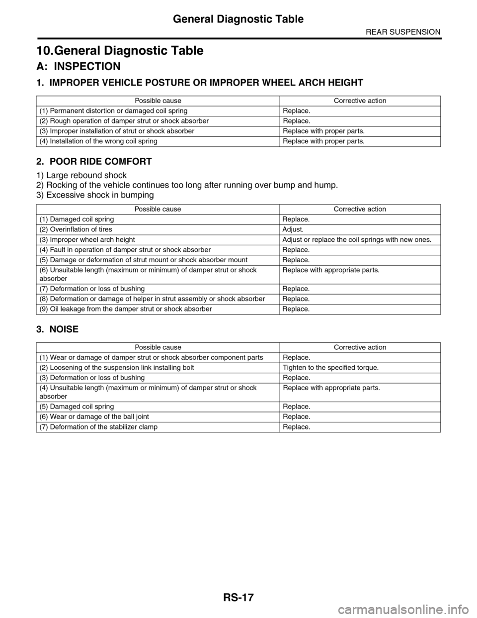
1. IMPROPER VEHICLE POSTURE OR IMPROPER WHEEL ARCH HEIGHT
2. POOR RIDE COMFORT
1) Large rebound shock
2) Rocking of the vehicle continues too long after running over bump and hump.
3) Excessive shock in bumping
3. NOISE
Po ss ibl e c a us e C o r r e ct ive ac ti o n
(1) Permanent distortion or damaged coil spring Replace.
(2) Rough operation of damper strut or shock absorber Replace.
(3) Improper installation of strut or shock absorber Replace with proper parts.
(4) Installation of the wrong coil spring Replace with proper parts.
Po ss ibl e ca us e C or r e ct i ve a ct io n
(1) Damaged coil spring Replace.
(2) Overinflation of tires Adjust.
(3) Improper wheel arch height Adjust or replace the coil springs with new ones.
(4) Fault in operation of damper strut or shock absorber Replace.
(5) Damage or deformation of strut mount or shock absorber mount Replace.
(6) Unsuitable length (maximum or minimum) of damper strut or shock
absorber
Replace with appropriate parts.
(7) Deformation or loss of bushing Replace.
(8) Deformation or damage of helper in strut assembly or shock absorber Replace.
(9) Oil leakage from the damper strut or shock absorber Replace.
Po ss ibl e c a us e C o r r e ct ive ac ti o n
(1) Wear or damage of damper strut or shock absorber component parts Replace.
(2) Loosening of the suspension link installing bolt Tighten to the specified torque.
(3) Deformation or loss of bushing Replace.
(4) Unsuitable length (maximum or minimum) of damper strut or shock
absorber
Replace with appropriate parts.
(5) Damaged coil spring Replace.
(6) Wear or damage of the ball joint Replace.
(7) Deformation of the stabilizer clamp Replace.
Page 1001 of 2453
VDC(diag)-9
General Description
VEHICLE DYNAMICS CONTROL (VDC) (DIAGNOSTICS)
3. General Description
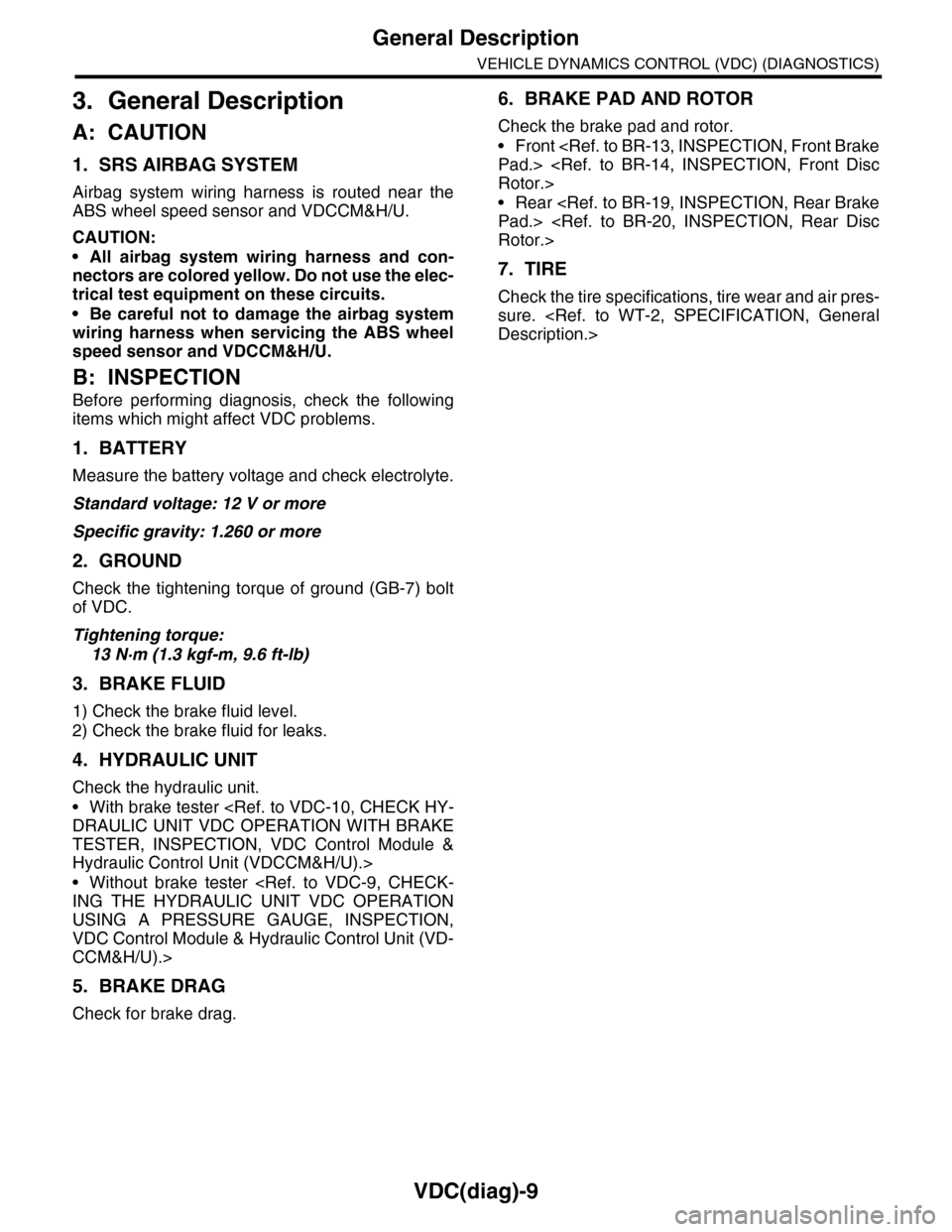
A: CAUTION
1. SRS AIRBAG SYSTEM
Airbag system wiring harness is routed near the
ABS wheel speed sensor and VDCCM&H/U.
CAUTION:
•All airbag system wiring harness and con-
nectors are colored yellow. Do not use the elec-
trical test equipment on these circuits.
•Be careful not to damage the airbag system
wiring harness when servicing the ABS wheel
speed sensor and VDCCM&H/U.
B: INSPECTION
Before performing diagnosis, check the following
items which might affect VDC problems.
1. BATTERY
Measure the battery voltage and check electrolyte.
Standard voltage: 12 V or more
Specific gravity: 1.260 or more
2. GROUND
Check the tightening torque of ground (GB-7) bolt
of VDC.
Tightening torque:
13 N·m (1.3 kgf-m, 9.6 ft-lb)
3. BRAKE FLUID
1) Check the brake fluid level.
2) Check the brake fluid for leaks.
4. HYDRAULIC UNIT
Check the hydraulic unit.
•With brake tester
TESTER, INSPECTION, VDC Control Module &
Hydraulic Control Unit (VDCCM&H/U).>
•Without brake tester
USING A PRESSURE GAUGE, INSPECTION,
VDC Control Module & Hydraulic Control Unit (VD-
CCM&H/U).>
5. BRAKE DRAG
Check for brake drag.
6. BRAKE PAD AND ROTOR
Check the brake pad and rotor.
•Front
•Rear
7. TIRE
Check the tire specifications, tire wear and air pres-
sure.
Page 1113 of 2453
WT-7
Aluminum Wheel
WHEEL AND TIRE SYSTEM
3. Aluminum Wheel
A: REMOVAL
1) Apply the parking brake, and position select le-
ver to “P” or “LOW”.
2) Set the shop jacks or a lift to the specified points,
and support the vehicle with its wheels slightly con-
tacting the floor.
3) Loosen the wheel nuts.
4) Raise the vehicle until its wheels are off the
ground using the jack or a lift.
5) Remove the wheel nuts and wheels.
NOTE:
•When removing the wheels, be careful not to
damage the hub bolts.
•Place the wheels with their outer sides facing up-
ward to prevent wheels from being damaged.
B: INSTALLATION
1) Remove dirt from the mating surface of the
wheel and brake rotor.
2) Attach the wheel to the hub by aligning the wheel
bolt holes with the hub bolts.
3) Temporarily attach the wheel nuts to the hub
bolts. (In the case of aluminum wheels, use SUBA-
RU genuine wheel nuts for aluminum wheels.)
4) Tighten the nuts by hand, making sure the wheel
hub hole is aligned correctly to the guide portion of
hub.
5) Tighten the wheel nuts in a diagonal selection to
the specified torque. Use a wheel nut wrench.
Wheel nut tightening torque:
110 N·m (11.2 kgf-m, 81.1 ft-lb)
CAUTION:
•Tighten the wheel nuts in two or three steps
by gradually increasing the torque on opposing
nuts, until they reach the specified torque.
•Do not push the wrench by foot. Always use
both hands when tightening the nuts.
•Make sure the bolt, nut and the nut seating
surface of the wheel are free from oil.
6) If a wheel is removed for replacement or for re-
pair of a puncture, retighten the wheel nuts to the
specified torque after driving 1,000 km (600 miles).
C: INSPECTION
1) Deformation or damage to the rim may cause air
leakage. Check the rim flange for deformation,
cracks or damage, and repair or replace as neces-
sary.
2) Jack-up the vehicle until wheels clear the floor.
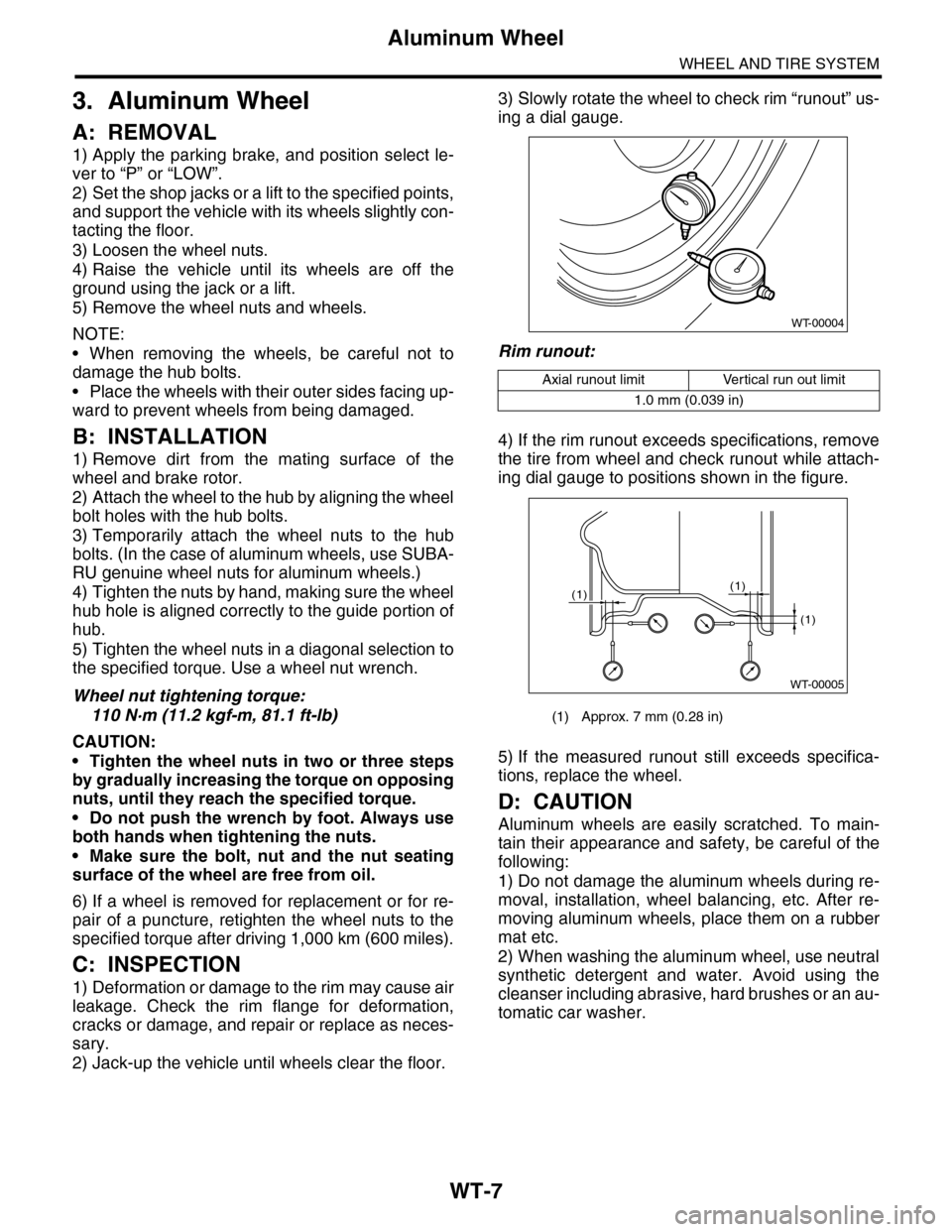
3) Slowly rotate the wheel to check rim “runout” us-
ing a dial gauge.
Rim runout:
4) If the rim runout exceeds specifications, remove
the tire from wheel and check runout while attach-
ing dial gauge to positions shown in the figure.
5) If the measured runout still exceeds specifica-
tions, replace the wheel.
D: CAUTION
Aluminum wheels are easily scratched. To main-
tain their appearance and safety, be careful of the
following:
1) Do not damage the aluminum wheels during re-
moval, installation, wheel balancing, etc. After re-
moving aluminum wheels, place them on a rubber
mat etc.
2) When washing the aluminum wheel, use neutral
synthetic detergent and water. Avoid using the
cleanser including abrasive, hard brushes or an au-
tomatic car washer.
Axial runout limit Vertical run out limit
1.0 mm (0.039 in)
(1) Approx. 7 mm (0.28 in)
WT-00004
WT-00005
(1)
(1)
(1)
Page 1603 of 2453
FU(H6DO)-42
Fuel Filler Pipe
FUEL INJECTION (FUEL SYSTEMS)
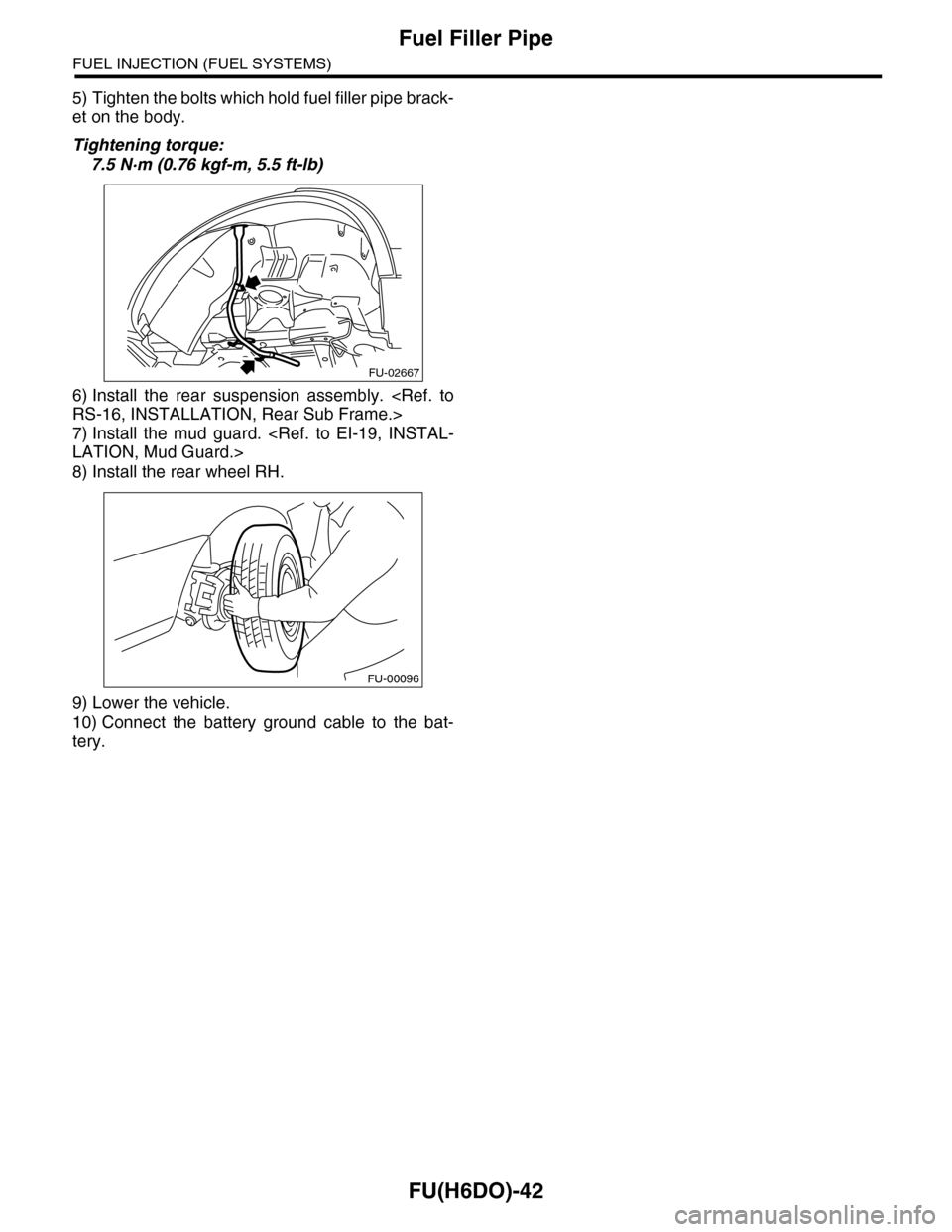
5) Tighten the bolts which hold fuel filler pipe brack-
et on the body.
Tightening torque:
7.5 N·m (0.76 kgf-m, 5.5 ft-lb)
6) Install the rear suspension assembly.
7) Install the mud guard.
8) Install the rear wheel RH.
9) Lower the vehicle.
10) Connect the battery ground cable to the bat-
tery.
FU-02667
FU-00096